CN213446509U - Rainwater collecting and utilizing system for urban viaduct - Google Patents
Rainwater collecting and utilizing system for urban viaduct Download PDFInfo
- Publication number
- CN213446509U CN213446509U CN202022117532.7U CN202022117532U CN213446509U CN 213446509 U CN213446509 U CN 213446509U CN 202022117532 U CN202022117532 U CN 202022117532U CN 213446509 U CN213446509 U CN 213446509U
- Authority
- CN
- China
- Prior art keywords
- water
- filter screen
- reservoir
- rainwater
- pipe
- Prior art date
- Legal status (The legal status is an assumption and is not a legal conclusion. Google has not performed a legal analysis and makes no representation as to the accuracy of the status listed.)
- Active
Links
Images


Classifications
-
- Y—GENERAL TAGGING OF NEW TECHNOLOGICAL DEVELOPMENTS; GENERAL TAGGING OF CROSS-SECTIONAL TECHNOLOGIES SPANNING OVER SEVERAL SECTIONS OF THE IPC; TECHNICAL SUBJECTS COVERED BY FORMER USPC CROSS-REFERENCE ART COLLECTIONS [XRACs] AND DIGESTS
- Y02—TECHNOLOGIES OR APPLICATIONS FOR MITIGATION OR ADAPTATION AGAINST CLIMATE CHANGE
- Y02A—TECHNOLOGIES FOR ADAPTATION TO CLIMATE CHANGE
- Y02A20/00—Water conservation; Efficient water supply; Efficient water use
- Y02A20/108—Rainwater harvesting
Abstract
The utility model discloses a city overpass rainwater collection utilizes system and application method thereof, city overpass rainwater collection utilizes system belongs to and improves bridge drainage and rainwater recovery and recycle technical field. The system provided by the utility model includes rainwater filtration system, afforestation irrigation system and filtration thing clearance system. The rainwater filtering system is used for filtering rainwater in 4 steps in rainy days, and is respectively used for filtering bridge deck, filtering a main drainage pipe, filtering a filter box and filtering a reservoir. The greening irrigation system is used for greening irrigation by using water in the reservoir through potential energy difference or a water pump in sunny days. The filtering material cleaning system is used for cleaning sundries on the filter screen, sediments in the filter box and the reservoir and a floating oil layer in the reservoir. The utility model discloses a set up 4 step filtration systems, rethread potential difference and water pump are used for the afforestation watering with the rainwater, have successfully solved rainy day bridge floor ponding problem and fine day afforestation irrigation problem.
Description
Technical Field
The utility model relates to an improve bridge drainage and rainwater recovery and recycle technical field, more specifically, a system is collected and utilized to city overpass rainwater.
Background
Bridges are engineering buildings for roads, pipelines, etc. to cross each other or over natural obstacles, and are an important part of transportation composition. The existing bridge drainage system has the phenomenon of blockage, so that the bridge deck is corroded, the durability is reduced, and the influence on traffic is caused by serious accumulated water on the bridge deck. Meanwhile, the demand of human beings on fresh water resources is increasing day by day, and in addition, the phenomenon of unreasonable water resource utilization exists, so that bridge drainage is indispensable as a recyclable water resource. Therefore, the drainage of the bridge and the recycling of water resources are very necessary.
Disclosure of Invention
In view of this, the main object of the present invention is to provide a rainwater collecting and utilizing system for urban viaduct to solve the problem of blockage in the existing beam drainage system and recycle the drainage of the bridge for greening irrigation.
In order to achieve the above purpose, the technical scheme of the utility model is as follows:
a rainwater collecting and utilizing system for urban viaducts comprises a rainwater filtering system, a greening irrigation system and a filter cleaning system.
The filtration system is divided into 4 steps, the first step: water enters the expandable filter screen cylinder (2) from the bridge floor for primary filtration; the second step is that: the water enters a longitudinal water discharge pipe (3) and is filtered for the second time through a filter screen 1 (5); the third step: water enters the filter box (9) through the vertical drain pipe (7) and is filtered for the third time; the fourth step: the water enters a reservoir (16) for water precipitation and oil removal. The greening irrigation system determines whether water is used for irrigation greening and how to irrigate greening through a water quality detector (20) and a water level sensor (19). The filtering material cleaning system comprises a filtering material collecting pipe (6), a filtering box (9) and a water storage tank (16).
Preferably, the expandable filter screen cylinder (2) is placed in the drainage branch pipe (1) movably, and when the expandable filter screen cylinder (2) is in a folded state, the expandable filter screen cylinder (2) is completely placed in the drainage branch pipe. When the expandable filter screen cylinder (2) is in an expanded state, one part of the expandable filter screen cylinder (2) is exposed out of the bridge floor and supported on the bridge floor, so that the drainage area is increased. Therefore, the expandable filter screen cylinder (2) can be expanded and folded to control the water discharge of the bridge. The drainage branch pipes (1) are fixed in the bridge deck, and the lower ends of the drainage branch pipes are directly communicated with the longitudinal drainage pipes (3).
Preferably, the bridge is provided with a certain longitudinal slope.
Preferably, the longitudinal drainage pipe (3) is fixed at the lower edge of the bridge deck plate through an elevator, the filter screens (1), (5) are arranged on the longitudinal drainage pipe (3) at intervals, a filtrate collecting pipe (6) is connected in front of the filter screens (1), (5), the lower end of the filtrate collecting pipe (6) is communicated with the longitudinal drainage pipe (3) through an elbow, and the upper end of the filtrate collecting pipe is vertical to the bridge deck plate and faces upwards until the filtrate collecting pipe is flush with the railings. The upper end of the vertical drain pipe (7) is communicated with the longitudinal drain pipe (3) through an elbow, and the lower end of the vertical drain pipe is communicated with the filter box (9).
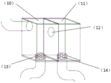
Preferably, the filter box (9) is divided into two chambers by a partition plate, a communication circular hole (12) is arranged in the middle for connection, meanwhile, a filter screen 2(13) and a connection drainage pipe are arranged below the chamber 1(10), a filter screen 3(14) and a connection drainage pipe are arranged below the chamber 2(11), the filter screen 2(13) and the filter screen 3(14) are arranged into a straw hat shape, a net-shaped structure is arranged at the drainage pipe, the upper part of the drainage pipe is in a hemispherical shape, and the aperture of the filter screen 3(14) is larger than that of the filter screen 2(13), so that the drainage capacity is enhanced.
Preferably, the pore sizes of the filter screen are ordered by: a deployable filter screen cylinder (2), a filter screen 1(5), a filter screen 3(14) and a filter screen 2 (13).
Preferably, the water storage tank (16) is communicated with the filter box (9) through a drain pipe, and the water storage tank (16) is divided into 3 areas by 2 clapboards, namely a settling area (21), an oil removing area (22) and a water supply area (23).
Preferably, the water storage tank is provided with 1 water inlet, 2 water outlets, an irrigation water outlet 1(25) is higher than the second partition plate (24) and lower than the sewage water outlet 2(26), and the sewage water outlet 2(26) is lower than the water inlet.
Preferably, a water level sensor (19) is installed in the reservoir (16).
Preferably, a water quality detector (20) is arranged in the water reservoir (16).
Preferably, the filtrate collection pipe (6) is cleaned on the bridge floor by a suction fan.
Preferably, the filter screens 2(13) and 3(14) are arranged in a straw hat shape, are arranged in a net structure at the drain pipe, are arranged in a hemispherical shape above the drain pipe, are used for filtering, filtrate can fall into the collecting area due to gradient, and the rest parts are not arranged in the filter screens.
The utility model aims at providing an above-mentioned urban viaduct rainwater is collected and is utilized application method of system still, including following step: bridge floor rainwater flows down from drainage branch pipe (1), through deployable filter screen section of thick bamboo (2), deployable filter screen section of thick bamboo (2) are the state of closing when the bridge floor displacement is not big, and deployable filter screen section of thick bamboo (2) are the state of opening when the bridge floor displacement is big, and deployable filter screen section of thick bamboo (2) filter great debris. The water continuously flows downwards to reach the reservoir (16) through twice filtration, sedimentation and oil removal treatment are carried out in the reservoir (16), and whether the water is used for irrigating and greening is judged by installing a water quality detector (20) in the reservoir (16). The water level sensor is used for automatically controlling whether the water is pressurized by the water pump (17) for irrigation and greening. Finally, the deployable filter screen cylinder (2), the filtered material collecting pipe (6), the filter box (9) and the reservoir (16) are cleaned. The expandable filter screen cylinder (2) is manually cleaned on the bridge floor. The filtrate in the filtrate collecting pipe (6) is cleaned on the bridge floor by a material suction fan. The sediment and the filtered matter in the filter box (9) can be accumulated at the bottom of the filter screen, and the filter screen is taken out for cleaning. The oily substances in the reservoir (16) are discharged to a sewage pipeline through a sewage discharge outlet. The sediment in the reservoir (16) is cleaned by opening the reservoir cover.
The beneficial effects of the utility model are that.
(1)4 level filtration system has solved the bridge floor jam problem and the bridge floor ponding problem of original bridge drainage system. The deployable filter screen (2) in the drainage branch pipe (1) can be adjusted by the rainfall. The middle of the filter box (9) is separated by a partition board, and the drainage mode can be automatically changed according to the drainage quantity.
(2) The cleaning of the filtered material collecting pipe (6) can be finished on the bridge floor, thus saving the manpower.
(3) The water storage tank (16) is separated by 3 partition plates, so that not only are fine particle substances in rainwater removed, but also oil substances with density lower than that of water in the rainwater are removed.
(4) A water quality detector (20) and a water level sensor (19) are arranged in the water storage tank (16) to determine whether water is used for irrigation greening or not and how to irrigate greening.
(5) The bridge drainage is collected into a reservoir (16), and then the rainwater is used for greening and irrigating through purification treatment, so that the purpose of recycling the rainwater is achieved.
Drawings
Fig. 1 is a schematic diagram of the overall structure of the present invention.
Fig. 2 is a schematic cross-sectional structure of the present invention.
Fig. 3 is a schematic view of the vertical section structure of the present invention.
Fig. 4 is a schematic view of a deployable filter screen cartridge configuration.
FIG. 5 is a schematic view of a filtrate collection tube configuration.
Fig. 6 is a schematic view of the filter box structure.
Fig. 7 is a schematic structural view of the filter screens 2 and 3.
Fig. 8 is a schematic view of the structure of the reservoir and the water pump.
Figure 9 is a schematic plan view of the reservoir.
Description of reference numerals:
(1) a drainage branch pipe; (2) an expandable filter screen cylinder; (3) a longitudinal water drainage pipe; (4) an elevator; (5) a filter screen 1; (6) a filtrate collecting pipe; (7) a vertical water drainage pipe; (8) and a hoop; (9) and a filter box; (10) a chamber 1; (11) a chamber 2; (12) the communication circular hole; (13) a filter screen 2; (14) a filter screen 3; (15) a bridge pier; (16) the water reservoir; (17) a water pump; (18) a sewage pipeline; (19) a water level sensor; (20) a water quality detector; (21) a settling zone; (22) an oil removing area; (23) a water supply area; (24) a second partition plate; (25) a water outlet 1; (26) and a water outlet 2.
Detailed Description
The following further description will be made in conjunction with the embodiments of the present invention, and it should be understood that the embodiments are only used for explaining and helping to understand the present invention, and do not constitute a limitation to the present invention.
In the description of the present invention, it should be noted that the terms "longitudinal", "upper", "lower", "left", "right", "vertical", "horizontal", "inner", "outer", "high", "low", and the like indicate orientations or positional relationships based on the orientations or positional relationships shown in the drawings, and are only for convenience of description and simplification of description, but do not indicate or imply that the device or element referred to must have a specific orientation, be constructed and operated in a specific orientation, and thus, should not be construed as limiting the present invention. Furthermore, the terms "first," "second," and "third" are used for descriptive purposes only and are not to be construed as indicating or implying relative importance. It is also noted that the terms "disposed," "mounted," "connected," "communicated," and "secured" are to be construed broadly unless otherwise specifically indicated and limited.
Unless defined otherwise, all technical and scientific terms used herein have the same meaning as commonly understood by one of ordinary skill in the art to which this invention belongs. The terminology used in the description of the invention herein is for the purpose of describing particular embodiments only and is not intended to be limiting of the invention.
As shown in fig. 1-9, a rainwater collecting and utilizing system for urban viaducts comprises a rainwater filtering system, a greening irrigation system and a filter cleaning system. The drainage branch pipe (1) penetrates through the bridge deck and is fixed inside the box girder, the expandable filter screen cylinder (2) is placed in the drainage branch pipe (1) on the bridge floor, the lower end of the drainage branch pipe (1) is connected with the longitudinal drainage pipe (3), and the longitudinal drainage pipe is fixed at the bottom of the bridge through the elevator (4). The inside of the longitudinal drainage pipe is provided with a filter screen 1(5) with a smaller aperture than the expandable filter screen cylinder (2). The front end of the filter screen 1(5) is connected with a filtrate collecting pipe (6) for collecting the filtrate of the longitudinal drain pipe (3). Vertical drain pipe (7) upper end is connected with vertical drain pipe (3) to it is fixed with staple bolt (8) to paste the case roof beam outer wall, and vertical drain pipe (7) lower extreme is connected and is placed rose box (9) on the pier tie beam, and the drain pipe is connected to rose box (9) lower extreme, and the drain pipe passes through staple bolt (8) to be fixed on pier (15), and the lower extreme is connected to cistern (16), uses drain pipe UNICOM between cistern (16) and rose box (9). The cistern deposits and deoils the processing to the rainwater. Two water outlets are arranged on the reservoir, a water outlet 1(25) at the lower part is connected with a water pump (17) for irrigating and greening, and a water outlet 2(26) at the upper part is connected with a sewage pipeline for discharging redundant water in the reservoir. A water level sensor (19) is arranged in the reservoir, and whether the water pump (17) is used or not is automatically controlled through the sensor (19). A water quality detector (20) is also arranged in the water storage tank, and only under the condition that the water quality reaches the standard, the water can be used for irrigating and greening. The cleaning of the filtered materials is carried out in dry seasons, namely the cleaning of the filtered material collecting pipe (6) and the cleaning of the filter box (9) and the reservoir (16).
As shown in figure 6, the filter box (9) is divided into a chamber 1(10) and a chamber 2(11) by a partition plate, a communication round hole (12) lower than the water inlet is dug on the partition plate, water flows to the chamber 2(11) through the chamber 1(10), a drain pipe is connected below the chamber 1(10) and the chamber 2(11), and a filter screen 2(13) and a filter screen 3(14) with different apertures are arranged above the drain pipe.
As shown in fig. 7, the filter nets 2 and 3 and 14 are arranged in a straw hat shape, a net structure is arranged at the position of the drain pipe, and the upper part is in a hemispherical shape.
As shown in fig. 8 to 9, the reservoir (16) is divided into 3 regions, a settling zone (21), an oil removing zone (22) and a water supply zone (23), by 2 partitions.
Although embodiments of the present invention have been shown and described, it will be understood by those skilled in the art that various changes, modifications, substitutions and alterations can be made to these embodiments without departing from the spirit and scope of the invention as defined by the appended claims and their equivalents.
Claims (9)
1. A rainwater collecting and utilizing system for an urban viaduct comprises a rainwater filtering system, a greening irrigation system and a filtered object cleaning system; the bridge is characterized in that a drainage branch pipe (1) penetrates through a bridge deck and is fixed inside a box girder, an expandable filter screen cylinder (2) is placed in the drainage branch pipe (1) on a bridge floor, the lower end of the drainage branch pipe (1) is connected with a longitudinal drainage pipe (3), and the longitudinal drainage pipe is fixed at the bottom of a bridge through an elevator (4); the inside of the longitudinal drainage pipe is provided with a filter screen 1(5) with a smaller aperture than the expandable filter screen cylinder (2); the front end of the filter screen 1(5) is connected with a filtrate collecting pipe (6) for collecting the filtrate of the longitudinal drain pipe (3); the upper end of a vertical drainage pipe (7) is connected with a longitudinal drainage pipe (3) and is fixed by a hoop (8) by sticking to the outer wall of a box girder, the lower end of the vertical drainage pipe (7) is connected with a filter box (9) placed on a bridge pier tie beam, the filter box (9) is divided into a chamber 1(10) and a chamber 2(11) by a partition plate, a communicating circular hole (12) lower than a water inlet is dug on the partition plate, water flows to the chamber 2(11) through the chamber 1(10), the drainage pipe is connected below the chamber 1(10) and the chamber 2(11), and a filter screen 2(13) and a filter screen 3(14) with different apertures are placed above the drainage pipe; the drain pipe is fixed on the pier (15) through the anchor ear (8), the lower end is connected to the reservoir (16), and the reservoir (16) carries out precipitation and deoiling treatment on rainwater; two water outlets are arranged on the reservoir (16), the water outlet 1(25) at the lower position is connected with a water pump (17) for irrigating and greening, and the water outlet 2(26) at the upper position is connected with a sewage pipeline (18) for discharging redundant water in the reservoir; a water level sensor (19) is arranged in the reservoir, and whether the water pump (17) is used or not is automatically controlled through the sensor (19); a water quality detector (20) is also arranged in the water storage tank, and only under the condition that the water quality reaches the standard, the water can be used for irrigating and greening.
2. The rainwater collecting and utilizing system for urban viaducts of claim 1, wherein: sorting the sizes of the filter screen apertures: deployable filter screen cylinder (2), filter screen 1(5), filter screen 3(14), filter screen 2 (13).
3. The rainwater collecting and utilizing system for urban viaducts of claim 2, wherein: the expandable filter screen cylinder (2) can be expanded and folded to control the water discharge of the adaptive bridge.
4. The rainwater collecting and utilizing system for urban viaducts of claim 2, wherein: the filter box is divided into two chambers by a partition plate, a communication round hole (12) is arranged in the middle for connection, the chambers 1 and 10 play a role of sedimentation, meanwhile, filter screens 2 and 13 and a connection drainage pipe are arranged below the chambers 1 and 10, water in the chambers 1 and 10 flows into the chambers 2 and 11 through the round holes, filter screens 3 and 14 and the connection drainage pipe are arranged below the chambers 2 and 11, and the filter screens 3 and 14 are larger than the filter screens 2 and 13 in the aperture of the filter screens because the water flowing into the chambers 2 and 11 is settled, so that the drainage capacity is enhanced.
5. The rainwater collecting and utilizing system for urban viaducts of claim 4, wherein: the filter screens 2(13) and 3(14) are arranged in a straw hat shape, a net-shaped structure is arranged at the position of the drain pipe, the upper part of the filter screen is in a hemispherical shape and used for filtering, filtered substances fall into the collecting area due to the gradient, and the rest parts are not arranged in the filter screens and used for collecting sediments and sundries falling from the filter screens.
6. The rainwater collecting and utilizing system for urban viaducts of claim 2, wherein: the reservoir (16) is divided into 3 areas by 2 clapboards, which are a settling area (21), an oil removing area (22) and a water supply area (23), silt sediments are deposited in the settling area (21) due to gravity, and oil substances with low density float in the oil removing area (22) due to buoyancy.
7. The rainwater collecting and utilizing system for urban viaducts of claim 1, wherein: a filtered matter collecting pipe (6) is arranged in front of the filtering net 1(5) arranged in the longitudinal water discharging pipe, and before water passes through the filtering net, filtered matters can be blocked and fall into the filtered matter collecting pipe (6) due to the action of gravity until the water in the filtered matter collecting pipe (6) is dried up, and a material sucking fan is used on the bridge floor to suck out the filtered matters, so that the function of cleaning the filtered matters is achieved.
8. The rainwater collecting and utilizing system for urban viaducts of claim 1, wherein: two water outlets are arranged on the reservoir, the water outlet 1(25) at the lower part is connected with a water pump (17), a water level sensor (19) is arranged in the reservoir, and whether the water pump (17) is used or not is automatically controlled through the sensor (19); when the water level is higher than the height of the greening position, the greening is irrigated by utilizing the potential energy difference; when the water level is lower than the elevation of the greening position, the water pump is used for irrigating the greening.
9. The rainwater collecting and utilizing system for urban viaducts of claim 1, wherein: a water quality detector (20) is arranged in the water storage tank, and the water quality detector (20) transmits information to determine whether the water in the tank can be used for irrigating and greening.
Priority Applications (1)
| Application Number | Priority Date | Filing Date | Title |
|---|---|---|---|
| CN202022117532.7U CN213446509U (en) | 2020-09-24 | 2020-09-24 | Rainwater collecting and utilizing system for urban viaduct |
Applications Claiming Priority (1)
| Application Number | Priority Date | Filing Date | Title |
|---|---|---|---|
| CN202022117532.7U CN213446509U (en) | 2020-09-24 | 2020-09-24 | Rainwater collecting and utilizing system for urban viaduct |
Publications (1)
| Publication Number | Publication Date |
|---|---|
| CN213446509U true CN213446509U (en) | 2021-06-15 |
Family
ID=76326385
Family Applications (1)
| Application Number | Title | Priority Date | Filing Date |
|---|---|---|---|
| CN202022117532.7U Active CN213446509U (en) | 2020-09-24 | 2020-09-24 | Rainwater collecting and utilizing system for urban viaduct |
Country Status (1)
| Country | Link |
|---|---|
| CN (1) | CN213446509U (en) |
-
2020
- 2020-09-24 CN CN202022117532.7U patent/CN213446509U/en active Active
Similar Documents
| Publication | Publication Date | Title |
|---|---|---|
| CN111995099A (en) | Rainwater collecting and utilizing system for urban viaduct and using method thereof | |
| CN104947781B (en) | The system of regulating and storing on a kind of rainwater-collecting shunting, self-restraint stratum | |
| CN106245734A (en) | The urban road rainwater-collecting improved, the system of regulating and storing conserving greenery patches | |
| CN106284588A (en) | A kind of rainwater treatment that can be used for sponge city and stocking system | |
| KR100524151B1 (en) | The collecting appratus for purified rainwater excluding the first flush | |
| CN113175050B (en) | Sponge urban rainwater collection and utilization system | |
| KR101096768B1 (en) | Rainwater utility system | |
| CN103408156A (en) | Method and system for comprehensively purifying, collecting and utilizing overpass rainwater | |
| CN204781254U (en) | Regulation system on reposition of redundant personnel, self -restraint stratum is collected to rainwater | |
| CN109797839A (en) | A kind of efficient pollution cutting device of urban road inlet for stom water and cut dirty operating method | |
| CN106978846A (en) | A kind of full collection anti-clogging Prefabricated combined septic tank with Control the Plan Pollution Sources function | |
| CN109372088A (en) | A kind of self-closed inlet for stom water of easy cleaning | |
| CN209457129U (en) | A kind of self-closed inlet for stom water of easy cleaning | |
| KR101574644B1 (en) | A Rainwater Gathering Equipment | |
| CN213446509U (en) | Rainwater collecting and utilizing system for urban viaduct | |
| CN213805773U (en) | Water collecting device of residential area sponge facility | |
| CN109518793A (en) | A kind of anti-blocking rain sewer system and its application method | |
| CN214994272U (en) | Rural rainwater collection device | |
| CN210013120U (en) | Water drainage device for all-dimensional collecting and draining bridge floor rainwater | |
| CN211571912U (en) | Urban rainwater collection water level control system | |
| CN207871715U (en) | Rural rainwater purification pond | |
| CN209482432U (en) | A kind of anti-blocking rain sewer system | |
| CN112031169A (en) | Assembled box type house with rainwater collecting function | |
| CN108118769B (en) | Sponge urban rainwater holds and oozes clean system | |
| CN212689073U (en) | Green energy-saving building rainwater collecting and processing system |
Legal Events
| Date | Code | Title | Description |
|---|---|---|---|
| GR01 | Patent grant | ||
| GR01 | Patent grant |