CN213355749U - Lifting machine and goods lifting system - Google Patents
Lifting machine and goods lifting system Download PDFInfo
- Publication number
- CN213355749U CN213355749U CN202021970317.5U CN202021970317U CN213355749U CN 213355749 U CN213355749 U CN 213355749U CN 202021970317 U CN202021970317 U CN 202021970317U CN 213355749 U CN213355749 U CN 213355749U
- Authority
- CN
- China
- Prior art keywords
- guide
- goods
- lifting
- telescopic fork
- driving
- Prior art date
- Legal status (The legal status is an assumption and is not a legal conclusion. Google has not performed a legal analysis and makes no representation as to the accuracy of the status listed.)
- Active
Links
Images


Landscapes
- Warehouses Or Storage Devices (AREA)
Abstract
The utility model relates to a storage logistics technical field specifically discloses a lifting machine and goods lift system. The utility model provides a lifting machine and goods lift system adopts flexible fork to carry cargo bed and get and put goods, sets up the transfer platform on the goods shelves body, and the transfer platform has played the effect of the workbin of keeping in, and this structure has replaced and has set up the roller line on every layer of laying things, the structure of roller formula cargo bed and the butt joint of roller line, to higher warehouse, can show the saving cost, and improved the reliability of operation; the telescopic fork loading platform is directly butted with the goods shelf body, and the hoister can be arranged in the goods shelf body without being limited at the end part of the goods shelf body, so that the flexibility of the layout of the storage system is improved; in addition, for a warehouse with a longer roadway, a plurality of hoists can be arranged in one roadway, so that the layer changing efficiency of the material box is obviously improved; in addition, the telescopic fork cargo carrying platform adopts a centering clamping mode, can be suitable for workbins of different sizes and ensures that the central position of the workbin is kept unchanged.
Description
Technical Field
The utility model relates to a storage logistics technical field especially relates to a lifting machine and goods lift system.
Background
The shuttle type goods shelf is a task of placing a shuttle vehicle in one or more roadways and finishing goods taking and placing by the shuttle vehicle. The shuttle type goods shelf has high storage density, can effectively improve the utilization rate of a warehouse, has high working efficiency and greatly reduces the waiting time of operation. The bin elevator is an important component of the shuttle type goods shelf, can directly carry bins to a specified goods layer without changing the layer by using a shuttle, and can improve the efficiency of a warehouse. The existing bin elevator generally adopts a roller as a cargo carrying platform, and a fixed roller line is installed on each layer of cargo rack and is in butt joint with the roller cargo carrying platform, so that the bin elevator is higher in use cost, complex in structure and poor in stability for a high-rise warehouse. Because the workbin elevator and the goods shelf need to be in interlayer line butt joint, the workbin elevator is generally installed at two ends of the goods shelf, and the layout of the workbin elevator is limited for a warehouse with a large area.
SUMMERY OF THE UTILITY MODEL
An object of the utility model is to provide a lifting machine and goods lift system, simple structure, it is with low costs, use the reliability high.
To achieve the purpose, the utility model adopts the following technical proposal:
a hoist, comprising:
the telescopic fork cargo carrying platform can extend out or retract to clamp or place the material box;
the telescopic fork loading platform is arranged on the lifting frame mechanism;
the lifting frame mechanism is arranged on the lifting guide mechanism in a sliding manner;
and the lifting driving mechanism is used for driving the lifting frame mechanism to move along the lifting guide mechanism.
Preferably, the telescopic fork loading platform comprises:
the cross-section of two relative settings carries cargo bed, the cross-section that carries cargo bed is L shape, the diaphragm that carries cargo bed is used for bearing the workbin, the riser that carries cargo bed is equipped with the flexible fork that can stretch out or retract along the first direction, the both ends of flexible fork all are equipped with the driving lever.
Preferably, the telescopic fork loading platform further comprises:
the clamping driving mechanism is used for driving the two cargo carrying platforms to mutually approach or depart from each other along a second direction, and the first direction and the second direction are vertical in the same plane;
and the telescopic driving mechanism is used for driving the telescopic fork to extend or retract.
Preferably, the clamping drive mechanism includes:
the transmission assembly comprises a synchronous belt and a synchronous belt motor, the two cargo carrying platforms are respectively connected with the synchronous belt, and the synchronous belt motor drives the synchronous belt to rotate to drive the two cargo carrying platforms to be close to or far away from each other;
the lower surface of the cargo carrying platform is provided with a sliding block which is connected with the sliding rail in a matching way.
Preferably, the telescopic driving mechanism includes:
the goods carrying platform is arranged on the guide shaft in a sliding manner;
the chain wheel is arranged on the guide shaft and connected with the telescopic fork through a chain wheel transmission assembly;
and the chain wheel driving motor drives the chain wheel to rotate so as to drive the telescopic fork to move along the first direction.
Preferably, the lifting guide mechanism comprises an even number of guide rails which are symmetrically arranged, and a top plate and a bottom plate which are connected with two ends of the guide rails, the top plate is fixed on the goods shelf body, the bottom plate is connected with the ground, two adjacent guide rails are connected through a connecting assembly, the guide rails are aluminum alloy sections with L-shaped sections, and the guide rails are provided with mounting surfaces and guide surfaces for mounting the connecting assembly.
Preferably, the guide rails are provided with a first mounting surface and a second mounting surface, and the connecting assembly comprises a first connecting piece and a second connecting piece, wherein the first connecting piece is used for connecting the first mounting surfaces of the two adjacent guide rails, and the second connecting piece is used for connecting the second mounting surfaces of the two adjacent guide rails.
Preferably, the hoisting frame mechanism comprises two parallel side plates, a middle plate and a mounting plate, the middle plate is connected with the mounting plate, the mounting plate is used for mounting the telescopic fork cargo carrying platform, each side plate is provided with at least one group of guide wheel set, and the guide wheel set comprises a front guide wheel and a rear guide wheel which are respectively matched with a first guide surface and a third guide surface of the guide rail, and a side guide wheel matched with a second guide surface of the guide rail.
Preferably, the lift drive mechanism comprises:
a lifting drive motor;
the belt wheel transmission box is arranged on the bottom plate, and the input end of the belt wheel transmission box is connected with the output shaft of the lifting drive motor;
the top driven belt wheel is arranged on the top plate;
promote the hold-in range, top driven pulleys with the pulley gear case passes through promote synchronous belt drive and connect, hoisting frame mechanism with it connects to promote the hold-in range.
The utility model also provides a goods lift system, including foretell lifting machine, still include:
the lifting device comprises a plurality of goods shelf bodies, a plurality of lifting device bodies and a lifting device, wherein each goods shelf body is provided with a plurality of placing layers from top to bottom, each placing layer is provided with at least one transfer table, and the mounting position of the lifting device is configured to enable the telescopic fork goods carrying table to take and place goods from the transfer table;
the shuttle car is used for conveying the material box on the transfer platform to the designated position of the shelf body or conveying the material box on the designated position of the shelf body to the transfer platform.
The utility model has the advantages that:
the utility model provides a flexible fork in lifting machine is carried cargo bed and is got or place the workbin with the mode clamp that stretches out or retract, convenient operation, simple structure can imbed between the goods shelves, has solved among the prior art problem that the lifting machine can only be installed at goods shelves both ends, to the great warehouse of area, the utility model provides a mounted position of lifting machine can not receive the restriction.
The utility model provides a goods lifting system includes above-mentioned lifting machine, and the lifting machine adopts the flexible fork to carry the cargo bed and gets and put the goods, sets up the transfer platform on the goods shelves body, and the transfer platform has played the effect of keeping in the workbin, and this structure has replaced and has set up the roller line on every layer of laying things, and the structure of roller formula carrying platform and roller line butt joint can show the saving cost to higher warehouse, and has improved the reliability of operation; in addition, the telescopic fork loading platform is directly butted with the goods shelf body, and the hoister can be arranged in the goods shelf body without being limited at the end part of the goods shelf body, so that the flexibility of the layout of the storage system is improved; in addition, for a warehouse with a longer roadway, a plurality of hoists can be arranged in one roadway, so that the layer changing efficiency of the material box is obviously improved; in addition, the telescopic fork cargo carrying platform adopts a centering clamping mode, can be suitable for workbins of different sizes and ensures that the central position of the workbin is kept unchanged.
Drawings
Fig. 1 is a schematic structural view of a telescopic fork loading platform of a shelf provided by the embodiment of the invention extending out;
fig. 2 is a schematic structural view illustrating a retractable fork loading platform of a shelf according to an embodiment of the present invention;
fig. 3 is a schematic structural diagram of a hoisting machine according to an embodiment of the present invention;
fig. 4 is a schematic structural diagram of a guide rail provided in an embodiment of the present invention;
fig. 5 is a schematic structural diagram of a first view angle of a hoisting frame guide mechanism according to an embodiment of the present invention;
fig. 6 is a schematic structural diagram of a second view angle of the hoisting frame guide mechanism according to the embodiment of the present invention;
fig. 7 is a schematic structural diagram of a front guide wheel and a rear guide wheel provided in an embodiment of the present invention;
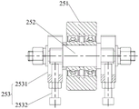
fig. 8 is a schematic structural view of a side guide wheel provided in an embodiment of the present invention;
fig. 9 is a schematic structural view of a pallet loading platform of the telescopic fork according to an embodiment of the present invention.
In the figure:
1. a lift guide mechanism; 11. a guide rail; 111. a guide surface; 112. a mounting surface; 12. a connecting assembly; 121. a first connecting member; 122. a second connecting member;
2. a lifting frame mechanism; 21. a side plate; 22. a middle plate;
23. a front guide wheel; 231. a first encapsulated roller; 232. a front guide roller shaft;
24. a rear guide wheel; 241. a second encapsulated roller; 242. a rear guide roller shaft; 243. a first adjustment assembly; 2431. an adjusting seat; 2432. a fixed seat; 2433. adjusting the screw rod; 2434. a nut;
25. a side guide wheel; 251. a third rubber-coated roller; 252. a side guide roller shaft; 253. a second adjustment assembly; 2531. a support plate; 2532. and (4) bolts.
26. Mounting a plate;
3. a top plate;
4. a lift drive mechanism; 41. a lifting drive motor; 42. a pulley transmission case; 43. a top driven pulley;
5. a telescopic fork loading platform; 51. a cargo carrying platform; 52. a telescopic fork; 53. a deflector rod; 541. a transmission assembly; 5411. a synchronous belt; 5412. a synchronous belt motor; 542. a slide rail; 551. a guide shaft; 552. a sprocket;
6. a shelf body; 61. a support beam; 62. a cross beam; 63. erecting a beam;
7. a base plate;
8. a material box;
a. a first direction; b. a second direction.
Detailed Description
In order to make the technical problem solved by the present invention, the technical solutions adopted by the present invention and the technical effects achieved by the present invention clearer, the following will be described in further detail with reference to the accompanying drawings, and obviously, the described embodiments are only some embodiments of the present invention, but not all embodiments. Based on the embodiments in the present invention, all other embodiments obtained by the skilled in the art without creative work belong to the protection scope of the present invention.
In the description of the present invention, unless expressly stated or limited otherwise, the terms "connected," "connected," and "fixed" are to be construed broadly, e.g., as meaning permanently connected, detachably connected, or integral to one another; can be mechanically or electrically connected; either directly or indirectly through intervening media, either internally or in any other relationship. The specific meaning of the above terms in the present invention can be understood in specific cases to those skilled in the art.
In the present disclosure, unless expressly stated or limited otherwise, the first feature "on" or "under" the second feature may comprise direct contact between the first and second features, or may comprise contact between the first and second features not directly. Also, the first feature being "on," "above" and "over" the second feature includes the first feature being directly on and obliquely above the second feature, or merely indicating that the first feature is at a higher level than the second feature. A first feature being "under," "below," and "beneath" a second feature includes the first feature being directly under and obliquely below the second feature, or simply meaning that the first feature is at a lesser elevation than the second feature.
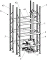
As shown in fig. 1 and fig. 2, the present embodiment provides a cargo lifting system, which includes a plurality of shelf bodies 6 and a lifter, where the shelf bodies 6 are provided, each shelf body 6 is provided with a plurality of storage layers from top to bottom, and each storage layer is provided with at least one transfer platform; the mounting position of the hoist is configured to enable the telescopic fork load table 5 to pick and place the goods from the transfer table. The automatic material conveying device further comprises a shuttle vehicle, wherein the shuttle vehicle is used for conveying the material box 8 on the transfer platform to the designated position of the shelf body 6 or conveying the material box 8 on the designated position of the shelf body 6 to the transfer platform.
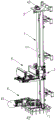
Combine fig. 2 and fig. 3, in this embodiment, the lifting machine includes flexible fork and carries cargo bed 5, hoisting frame mechanism 2, promote guiding mechanism 1 and promotion actuating mechanism 4, flexible fork carries cargo bed 5 can stretch out or retract in order to press from both sides and get or place workbin 8, flexible fork carries cargo bed 5 and installs on hoisting frame mechanism 2, hoisting frame mechanism 2 slidable mounting is on promoting guiding mechanism 1, it is used for driving hoisting frame mechanism 2 to remove along promoting guiding mechanism 1 to promote actuating mechanism 4, and then drive flexible fork and carry cargo bed 5 and reciprocate, and enable flexible fork and carry cargo bed 5 and can both stop at every layer of putting, so that realize getting goods and putting goods automatically. The flexible fork of lift in carries cargo bed 5 and gets or place workbin 8 with the mode clamp that stretches out or retract, convenient operation, simple structure can imbed between the goods shelves, has solved among the prior art problem that the lift can only be installed at goods shelves both ends, to the great warehouse of area, the utility model provides a mounted position of lift can not receive the restriction.
The goods lifting system in the embodiment adopts the telescopic fork goods carrying platform 5 to take and place goods, the goods shelf body 6 is provided with the transfer platform which plays a role of a temporary storage bin 8, and the structure replaces a structure that a roller line is arranged on each layer of goods carrying layer and the roller goods carrying platform is in butt joint with the roller line, so that for a relatively high warehouse, the cost can be obviously saved, and the operation reliability is improved; in addition, the telescopic fork loading platform 5 is directly butted with the goods shelf body 6, and the hoister can be arranged in the goods shelf body 6 without being limited to the end part of the goods shelf body 6, so that the flexibility of the layout of the storage system is improved; in addition, for a warehouse with a longer roadway, a plurality of hoists can be arranged in one roadway, so that the layer changing efficiency of the bin 8 is obviously improved; in addition, the telescopic fork loading platform 5 adopts a centering clamping mode, can be suitable for the workbins 8 with different sizes, and ensures that the central position of the workbins 8 is kept unchanged.
In this embodiment, goods shelves body 6 includes two sets of vertical support assembly that parallel and interval set up, and every vertical support assembly of group includes two at least intervals and parallel arrangement's perpendicular roof beam 63, is equipped with multilayer between two sets of vertical support assembly from top to bottom and puts the layer, puts a supporting beam 61 that the layer includes two at least intervals and sets up, and supporting beam 61's both ends are connected with perpendicular roof beam 63, and the transfer platform includes two at least crossbeams 62 that the interval set up, and crossbeam 62 is connected perpendicularly with supporting beam 61 in the coplanar. When the goods are taken, the shuttle trolley firstly places the material box 8 on the cross beam 62, and then the telescopic fork loading platform 5 of the elevator can extend to take the material box 8 back from the cross beam 62; when the hoister puts goods, the telescopic fork goods carrying platform 5 of the hoister firstly places the material box 8 on the cross beam 62, and then the material box 8 is taken away by the shuttle trolley. The transfer table provided by the embodiment has the advantages of simple structure and low use cost, and replaces the structure of the traditional roller line. In other embodiments, the transfer platform may have other structures, and is not limited herein.
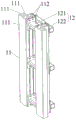
Referring to fig. 3 and 4, the lifting guide mechanism 1 includes an even number of symmetrically arranged guide rails 11, and a top plate 3 and a bottom plate 7 connected to both ends of the guide rails 11, the top plate 3 is fixed on the shelf body 6, the bottom plate 7 is connected to the ground, two adjacent guide rails 11 are connected by a connecting assembly 12, the guide rails 11 are aluminum alloy sections with L-shaped cross sections, and the guide rails 11 are provided with mounting surfaces 112 and guide surfaces 111 for mounting the connecting assembly 12. The mounting surfaces 112 of two adjacent guide rails 11 are connected through a connecting assembly 12, and the connecting assembly 12 can adjust the parallelism of the two guide rails 11. The guide surface 111 comprises a first guide surface, a second guide surface and a third guide surface which are sequentially connected, wherein the first guide surface is parallel to the third guide surface, and the first guide surface and the third guide surface are respectively vertical to the second guide surface, so that the lifting stability of the lifting frame mechanism 2 is improved. The bottom plate 7 is connected with the ground through bolts, and the levelness of the bottom plate 7 can be adjusted by screwing the bolts. In addition, the guide rail 11 adopts an aluminum alloy section to replace a steel column in the prior art, the surface of the aluminum alloy section has high smoothness, and the aluminum alloy section can be directly used as a guide surface without additional machining, so that the production cost is reduced; the aluminum alloy sections can be spliced into guide rails 11 with any height, can be suitable for high-rise warehouses, and has low assembly requirements; in addition, the aluminum alloy section is light in weight, is suitable for a lifter of a high-rise warehouse, and reduces the requirements on civil engineering and ground bearing capacity.
Further, the connecting assembly 12 includes a first connecting member 121 and a second connecting member 122, two ends of the first connecting member 121 are connected to the first mounting surfaces of the two adjacent guide rails 11, and two ends of the second connecting member 122 are connected to the two second mounting surfaces. In this embodiment, the first connecting member 121 and the second connecting member 122 are respectively disposed at least two, so as to improve the connection stability of the two guide rails 11, the first connecting member 121 can adjust the parallelism of the two guide rails 11, and the second connecting member 122 is disposed to facilitate the installation of the guide rails 11 on the frame body of the elevator.
In order to facilitate the connection of the mounting surface 112 with the first connecting piece 121 and the second connecting piece 122, the first mounting surface and the second mounting surface are respectively provided with two T-shaped grooves, the T-shaped grooves extend along the length direction of the guide rail 11, the first connecting piece 121 and the second connecting piece 122 are matched with the T-shaped grooves through T-shaped screws and connected with the guide rail 11, and the connecting structure is simple and convenient to operate.
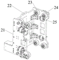
In the present embodiment, as shown in fig. 5 and 6, the lifting frame mechanism 2 includes two side plates 21 arranged in parallel, a middle plate 22 connecting the two side plates 21, and a mounting plate 26 connected to the middle plate 22, the mounting plate 26 is used for mounting the telescopic fork loading platform 5, at least one set of guide wheel set is arranged on each side plate 21, and the guide wheel set includes a front guide wheel 23 and a rear guide wheel 24 cooperating with the first guide surface and the third guide surface, and a side guide wheel 25 cooperating with the second guide surface. The axes of the front guide wheel 23 and the rear guide wheel 24 are parallel, the axis of the side guide wheel 25 is perpendicular to the axis of the front guide wheel 23, the three guide wheels are distributed in a triangular shape, the guide rail 11 is clamped, and the stable connection of the lifting frame mechanism 2 and the guide rail 11 is realized. In the present embodiment, two sets of guide wheels are provided on each side plate 21. The number of guide wheel sets is related to the height of the side plate 21, and is not limited to two sets.
As shown in fig. 7, the front guide wheel 23 includes a first rubber coating roller 231 and a front guide roller shaft 232, the first rubber coating roller 231 is rotatably connected to the front guide roller shaft 232, and the front guide roller shaft 232 is fixedly mounted on the side plate 21. The position of the first rubber coating roller 231 is not adjustable, the installation is convenient, the rubber coating roller is used as a guide wheel, the operation is stable, the noise is low, and the requirement on the assembly precision of the guide rail 11 is not high.
The rear guide wheel 24 includes a second rubber-covered roller 241, a rear guide roller shaft 242 and a first adjusting assembly 243, the second rubber-covered roller 241 is rotatably connected with the rear guide roller shaft 242, the first adjusting assembly 243 is movably mounted on the side plate 21, the rear guide roller shaft 242 is mounted on the first adjusting assembly 243, and the first adjusting assembly 243 can enable the second rubber-covered roller 241 to approach or depart from the guide rail 11, so that the second rubber-covered roller 241 contacts with a corresponding guide surface on the guide rail 11, and the stability of the connection of the lifting frame mechanism 2 and the guide rail 11 is further improved. The rubber-coated roller is used as a guide wheel, so that the rubber-coated roller runs stably, has low noise and has low requirement on the assembly precision of the guide rail 11.
In this embodiment, the first adjusting assembly 243 includes an adjusting base 2431, a fixing base 2432 and an adjusting screw 2433, the rear guide roller shaft 242 is fixedly installed on the adjusting base 2431, the fixing base 2432 is installed on the side plate 21, one end of the adjusting screw 2433 is fixedly connected with the adjusting base 2431, and the other end of the adjusting screw 2433 penetrates through the fixing base 2432 and is screwed with a nut 2434. The nut 2434 is screwed to enable the adjusting screw 2433 to drive the adjusting seat 2431 to move close to or away from the fixing seat 2432, so that the structure is simple and the adjustment is convenient. In other embodiments, the first adjusting assembly 243 may also have other structures, and is not limited herein.
As shown in fig. 8, the side guide wheel 25 includes a third rubber covered roller 251, a side guide roller shaft 252 and a second adjustment assembly 253, the third rubber covered roller 251 is rotatably connected with the side guide roller shaft 252, the second adjustment assembly 253 is mounted on the side plate 21, the side guide roller shaft 252 is mounted on the second adjustment assembly 253, and the second adjustment assembly 253 enables the third rubber covered roller 251 to approach or move away from the guide rail 11. Specifically, a mounting hole is formed in the side plate 21, the second adjusting assembly 253 is mounted on the outer side of the side plate 21, so that the position of the third rubber-covered roller 251 can be adjusted conveniently, and the third rubber-covered roller 251 penetrates through the mounting hole to be in contact with the guide surface of the guide rail 11. The rubber-coated roller is used as a guide wheel, so that the rubber-coated roller runs stably, has low noise and has low requirement on the assembly precision of the guide rail 11.
In this embodiment, the second adjustment assembly 253 includes two support plates 2531 disposed at an interval, two ends of the side guide roller shaft 252 are movably mounted on the two support plates 2531, a bolt 2532 is screwed to the support plate 2531, and the end of the bolt 2532 abuts against the side guide roller shaft 252 by adjusting the bolt 2532. Two bolts 2532 are screwed, and the bolts 2532 abut against the side guide roller shafts 252 to push the side guide roller shafts 252 to move towards the guide rail 11, so as to drive the third rubber-covered roller 251 to approach the guide rail 11. In other embodiments, the second adjustment assembly 253 may have other structures, which are not limited herein.
Promote actuating mechanism 4 and be used for driving hoisting frame mechanism 2 and remove along promoting guiding mechanism 1, continue to refer to fig. 3, in this embodiment, promote actuating mechanism 4 including promoting driving motor 41, pulley gear box 42, top driven pulley 43 and promotion hold-in range (not shown in the figure), it all installs on bottom plate 7 to promote driving motor 41 and pulley gear box 42, pulley gear box 42's input and the output shaft who promotes driving motor 41, top driven pulley 43 installs on roof 3, top driven pulley 43 is connected through promoting hold-in range transmission with pulley gear box 42, hoisting frame mechanism 2 is connected with the promotion hold-in range. Specifically, a driving synchronous pulley, a driven synchronous pulley and a guide wheel are arranged in the pulley transmission case 42, and an output shaft of the lifting drive motor 41 is connected with the driving synchronous pulley through a coupler, a driving shaft and a tensioning sleeve. Promote the one end of hold-in range and install on the medium plate 22 of hoisting frame mechanism 2, specifically, be equipped with the hold-in range clamp plate on the medium plate 22, promote the hold-in range and be connected with the hold-in range clamp plate. The other end of the lifting synchronous belt is sequentially connected with a guide wheel, a driving synchronous pulley, a driven synchronous pulley and a top driven pulley 43, and then the end part of the lifting synchronous belt is installed in a tensioning mechanism arranged on the middle plate 22 of the lifting frame mechanism 2.
The telescopic fork cargo carrying platform 5 has the functions of telescoping and clamping the material box 8, in the embodiment, as shown in fig. 9, the telescopic fork cargo carrying platform 5 comprises two oppositely arranged cargo carrying platforms 51 and a clamping and clamping driving mechanism, the cross section of the cargo carrying platform 51 is in an L shape, the transverse plate of the cargo carrying platform 51 is used for carrying the material box 8, the vertical plate of the cargo carrying platform 51 is provided with a telescopic fork 52 which can extend out or retract along a first direction a, and the two ends of the telescopic fork 52 are both provided with shift levers 53 used for pushing the material box 8. The clamping driving mechanism is used for driving the two cargo carrying platforms 51 to approach or depart from each other along a second direction b, and the first direction a and the second direction b are perpendicular in the same plane. The telescopic driving mechanism is used to drive the telescopic fork 52 to extend or retract. Two carry cargo bed 51 can adjust the distance between the two according to the actual size of workbin, and flexible fork 52 removes along with carrying cargo bed 51 to be adapted to press from both sides the workbin 8 of embracing not unidimensional, flexible fork 52 can stretch out and retract, realizes workbin 8's location simultaneously with the cooperation of driving lever 53, when flexible fork 52 presss from both sides the armful, driving lever 53 promotes workbin 8 and removes, has improved the stability that flexible fork carries cargo bed 5 clamp and gets workbin 8.
In this embodiment, the driving lever 53 is rotatably connected to the telescopic fork 52, when the work bin 8 needs to be pushed, the driving lever 53 rotates downward and is perpendicular to the surface of the telescopic fork 52, when the work bin 8 does not need to be pushed, the driving lever 53 rotates upward and is parallel to the surface of the telescopic fork 52, preferably, the surface of the telescopic fork 52 is provided with a receiving groove, and the driving lever 53 is disposed in the receiving groove.
The clamping and holding driving mechanism comprises a driving component 541, the driving component 541 comprises a synchronous belt 5411 and a synchronous belt motor 5412, two goods carrying platforms 51 are respectively connected with the synchronous belt 5411, one of the goods carrying platforms 51 is connected with an upper synchronous belt 5411, the other goods carrying platform 51 is connected with a lower synchronous belt 5411, and the synchronous belt motor 5412 drives the synchronous belt 5411 to rotate to drive the two goods carrying platforms 51 to be close to or far away from. In order to improve the running stability of the cargo carrying platform 51, the clamping driving mechanism further comprises a sliding rail 542, and a sliding block which is connected with the sliding rail 542 in a matching manner is arranged on the lower surface of the cargo carrying platform 51. In this embodiment, the sliding rail 542 is disposed at one side of the transmission assembly 541.
The telescopic driving mechanism comprises a guide shaft 551, the guide shaft 551 is arranged on the other side of the transmission component 541, the cargo carrying platform 51 is slidably mounted on the guide shaft 551, a chain wheel 552 is mounted on the guide shaft 551, the chain wheel 552 is connected with the telescopic fork 52 through a chain wheel transmission component, a chain wheel driving motor drives the chain wheel 552 to rotate, and the chain wheel 552 rotates to drive the chain wheel transmission component to move so as to drive the telescopic fork 52 to move along the first direction a. The construction of the sprocket drive assembly in this embodiment is prior art and will not be described in detail herein. In other embodiments, the telescopic driving mechanism may have other structures, and is not limited herein.
It is obvious that the above embodiments of the present invention are only examples for clearly illustrating the present invention, and are not intended to limit the embodiments of the present invention. Other variations and modifications will be apparent to persons skilled in the art in light of the above description. And are neither required nor exhaustive of all embodiments. Any modification, equivalent replacement, and improvement made within the spirit and principle of the present invention should be included in the protection scope of the claims of the present invention.
Claims (10)
1. A hoist, comprising:
the telescopic fork cargo carrying platform (5) can extend out or retract back to clamp or place the material box (8);
the lifting frame mechanism (2), the telescopic fork loading platform (5) is arranged on the lifting frame mechanism (2);
the lifting guide mechanism (1), the lifting frame mechanism (2) is installed on the lifting guide mechanism (1) in a sliding mode;
and the lifting driving mechanism (4) is used for driving the lifting frame mechanism (2) to move along the lifting guide mechanism (1).
2. The hoisting machine as claimed in claim 1, characterized in that the telescopic fork load table (5) comprises:
the cross-section of two relative goods carrying platform (51) that set up, goods carrying platform (51) is L shape, the diaphragm of goods carrying platform (51) is used for bearing workbin (8), the riser of goods carrying platform (51) is equipped with can follow first direction (a) and stretches out or flexible fork (52) of withdrawal, the both ends of flexible fork (52) all are equipped with driving lever (53).
3. The hoisting machine as claimed in claim 2, characterized in that the telescopic fork load table (5) further comprises:
the clamping driving mechanism is used for driving the two cargo carrying platforms (51) to be close to or far away from each other along a second direction (b), and the first direction (a) and the second direction (b) are perpendicular in the same plane;
and the telescopic driving mechanism is used for driving the telescopic fork (52) to extend or retract.
4. The hoist as claimed in claim 3, characterized in that the clamping drive mechanism comprises:
the transmission assembly (541) comprises a synchronous belt (5411) and a synchronous belt motor (5412), the two cargo carrying platforms (51) are respectively connected with the synchronous belt (5411), and the synchronous belt motor (5412) drives the synchronous belt (5411) to rotate to drive the two cargo carrying platforms (51) to be close to or far away from each other;
the lower surface of the cargo carrying platform (51) is provided with a sliding block which is connected with the sliding rail (542) in a matching way.
5. The hoist as claimed in claim 3, characterized in that the telescopic drive mechanism comprises:
the guide shaft (551), the said cargo bed (51) is installed on said guide shaft (551) slidably;
a chain wheel (552) mounted on the guide shaft (551), the chain wheel (552) and the telescopic fork (52) being connected through a chain wheel transmission assembly;
a chain wheel driving motor for driving the chain wheel (552) to rotate so as to drive the telescopic fork (52) to move along the first direction (a).
6. The hoisting machine as claimed in claim 1, characterized in that the hoisting guide mechanism (1) comprises an even number of symmetrically arranged guide rails (11) and a top plate (3) and a bottom plate (7) connected to both ends of the guide rails (11), the top plate (3) is fixed to the rack body (6), the bottom plate (7) is connected to the ground, two adjacent guide rails (11) are connected by a connecting assembly (12), the guide rails (11) are of an L-shaped section, and the guide rails (11) are provided with mounting surfaces and guide surfaces for mounting the connecting assembly (12).
7. The hoisting machine as claimed in claim 6, characterized in that the guide rails (11) are provided with a first mounting surface and a second mounting surface, and the connecting assembly (12) comprises a first connecting member (121) connecting the first mounting surfaces of two adjacent guide rails (11) and a second connecting member (122) connecting the two second mounting surfaces.
8. The hoisting machine as claimed in claim 6, characterized in that the hoisting frame mechanism (2) comprises two side plates (21) arranged in parallel, a middle plate (22) connecting the two side plates (21) and a mounting plate (26) connected to the middle plate (22), the mounting plate (26) being used for mounting the telescopic fork pallet (5), at least one set of guide wheel sets being provided on each side plate (21), the guide wheel sets comprising a front guide wheel (23) and a rear guide wheel (24) cooperating with the first guide surface and the third guide surface of the guide rail (11), respectively, and a side guide wheel (25) cooperating with the second guide surface of the guide rail (11).
9. Hoisting machine as claimed in claim 6, characterized in that the hoisting drive mechanism (4) comprises:
a lift drive motor (41);
the belt wheel transmission box (42) is arranged on the bottom plate (7), and the input end of the belt wheel transmission box (42) is connected with the output shaft of the lifting drive motor (41);
a top driven pulley (43) mounted on the top plate (3);
promote the hold-in range, top driven pulley (43) with pulley drive case (42) pass through promote synchronous belt drive and connect, hoisting frame mechanism (2) with it connects to promote the hold-in range.
10. A cargo lifting system comprising the hoist as claimed in any one of claims 1 to 9, further comprising:
the goods shelf comprises a plurality of goods shelf bodies (6), wherein each goods shelf body (6) is provided with a plurality of goods placing layers from top to bottom, each goods placing layer is provided with at least one transfer table, and the installation position of the hoister is configured to enable the telescopic fork goods carrying table (5) to take and place goods from the transfer table;
the shuttle car is used for conveying the material box (8) on the transfer table to the designated position of the shelf body (6) or conveying the material box (8) on the designated position of the shelf body (6) to the transfer table.
Priority Applications (2)
| Application Number | Priority Date | Filing Date | Title |
|---|---|---|---|
| CN202021970317.5U CN213355749U (en) | 2020-09-10 | 2020-09-10 | Lifting machine and goods lifting system |
| AU2021101280A AU2021101280A4 (en) | 2020-09-10 | 2021-03-12 | Lifter and goods lifting system |
Applications Claiming Priority (1)
| Application Number | Priority Date | Filing Date | Title |
|---|---|---|---|
| CN202021970317.5U CN213355749U (en) | 2020-09-10 | 2020-09-10 | Lifting machine and goods lifting system |
Publications (1)
| Publication Number | Publication Date |
|---|---|
| CN213355749U true CN213355749U (en) | 2021-06-04 |
Family
ID=76094276
Family Applications (1)
| Application Number | Title | Priority Date | Filing Date |
|---|---|---|---|
| CN202021970317.5U Active CN213355749U (en) | 2020-09-10 | 2020-09-10 | Lifting machine and goods lifting system |
Country Status (2)
| Country | Link |
|---|---|
| CN (1) | CN213355749U (en) |
| AU (1) | AU2021101280A4 (en) |
Cited By (3)
| Publication number | Priority date | Publication date | Assignee | Title |
|---|---|---|---|---|
| CN113526099A (en) * | 2021-06-28 | 2021-10-22 | 广汽菲亚特克莱斯勒汽车有限公司 | Automobile engine valve rod material distribution interfacing apparatus |
| CN114408441A (en) * | 2021-12-17 | 2022-04-29 | 太原福莱瑞达物流设备科技有限公司 | Multi-station quick elevator |
| CN115535514A (en) * | 2022-12-05 | 2022-12-30 | 沈阳新松机器人自动化股份有限公司 | Material box lifting machine |
-
2020
- 2020-09-10 CN CN202021970317.5U patent/CN213355749U/en active Active
-
2021
- 2021-03-12 AU AU2021101280A patent/AU2021101280A4/en active Active
Cited By (3)
| Publication number | Priority date | Publication date | Assignee | Title |
|---|---|---|---|---|
| CN113526099A (en) * | 2021-06-28 | 2021-10-22 | 广汽菲亚特克莱斯勒汽车有限公司 | Automobile engine valve rod material distribution interfacing apparatus |
| CN114408441A (en) * | 2021-12-17 | 2022-04-29 | 太原福莱瑞达物流设备科技有限公司 | Multi-station quick elevator |
| CN115535514A (en) * | 2022-12-05 | 2022-12-30 | 沈阳新松机器人自动化股份有限公司 | Material box lifting machine |
Also Published As
| Publication number | Publication date |
|---|---|
| AU2021101280A4 (en) | 2021-05-27 |
Similar Documents
| Publication | Publication Date | Title |
|---|---|---|
| CN213355749U (en) | Lifting machine and goods lifting system | |
| CN104444000B (en) | The vertical conveyer of steel drum tiered warehouse facility | |
| CN109094682B (en) | Omnidirectional logistics vehicle integrating lifting, dumping and multifunctional carrying | |
| CN211140612U (en) | RGV dolly | |
| CN106865275A (en) | A kind of container loading system of pallet line outer circulation | |
| CN107740620B (en) | Tunnel stack stereo garage | |
| CN2841586Y (en) | Stacker | |
| CN112978180A (en) | High-speed light-duty layer changing elevator | |
| CN210885144U (en) | Extensible AGV lifting device | |
| CN111977240A (en) | Box type composite elevator | |
| CN1958409A (en) | Stacking machine and stereo storage rack | |
| CN106639426B (en) | Mechanical parking garage vehicle carrying plate unstacking and stacking equipment and technology | |
| CN106639427B (en) | A kind of transverse shifting and the lateral vehicle-carrying plate frame apparatus plus longitudinal movement | |
| CN106938830B (en) | Cargo carrying device | |
| CN1874942A (en) | Materials conveying system | |
| CN110712935A (en) | Movable cloth raw material grabbing lifting frame | |
| CN216334440U (en) | Multilayer commodity circulation warehouse deposits a device fast | |
| CN217866948U (en) | Automatic stacking device for hollow rubber tables | |
| CN215401345U (en) | Brick feeding equipment for brick making machine | |
| CN212124958U (en) | Mould hoisting device | |
| CN2386033Y (en) | Multi-stage elevating platforms | |
| CN216071595U (en) | Logistics storage robot with multiple degrees of freedom | |
| CN207811168U (en) | A kind of elevator of coplanar lifting | |
| CN214692272U (en) | Novel parallel full-automatic car loader | |
| CN110861872A (en) | Double-station coiled material transfer device and method |
Legal Events
| Date | Code | Title | Description |
|---|---|---|---|
| GR01 | Patent grant | ||
| GR01 | Patent grant |