CN213333435U - Block terminal support that building site used - Google Patents
Block terminal support that building site used Download PDFInfo
- Publication number
- CN213333435U CN213333435U CN202022323074.2U CN202022323074U CN213333435U CN 213333435 U CN213333435 U CN 213333435U CN 202022323074 U CN202022323074 U CN 202022323074U CN 213333435 U CN213333435 U CN 213333435U
- Authority
- CN
- China
- Prior art keywords
- box body
- bearing box
- support
- bearing
- distribution box
- Prior art date
- Legal status (The legal status is an assumption and is not a legal conclusion. Google has not performed a legal analysis and makes no representation as to the accuracy of the status listed.)
- Active
Links
Images


Landscapes
- Conveying And Assembling Of Building Elements In Situ (AREA)
Abstract
The utility model discloses a block terminal support that building site used belongs to block terminal support technical field. The problem of the balance of current block terminal support is solved, a block terminal support that building site used, including the bearing box, be equipped with on the bearing box: the lifting mechanism is arranged on the bearing box body and used for adjusting the height of the distribution box; the balance mechanism is arranged at the bottom of the bearing box body and used for solving the balance problem of the distribution box support under different environments; the top of the lifting mechanism is provided with a distribution box, and the distribution box is positioned above the bearing box body; the lifting mechanism bottom is equipped with the moving member and is used for removing the block terminal, the moving member includes lath and universal wheel. The utility model discloses can be used as the block terminal support.
Description
Technical Field
The utility model relates to a block terminal support that building site used belongs to block terminal support technical field.
Background
The distribution box support is used for supporting the distribution box, and construction personnel can conveniently conduct construction operation.
The angle bar welding forms commonly used to the block terminal support of present job site, also has the construction unit to adopt the brick support, has played the supporting role to the block terminal, but is difficult to remove to the support height is unadjustable, can't satisfy the demand of different construction places to the block terminal height, and to the uneven job site of height, the balance problem of traditional block terminal support also is difficult to solve simultaneously.
To this end, we propose a support for a distribution box for use at a construction site that solves the above mentioned problems.
SUMMERY OF THE UTILITY MODEL
The utility model aims at solving the problem, and the block terminal support that the building site that provides was convenient for remove, height-adjustable just can carry out the leveling used.
In order to achieve the above purpose, the utility model adopts the following technical scheme:
the utility model provides a block terminal support that building site used, includes the bearing box, be equipped with on the bearing box:
the lifting mechanism is arranged on the bearing box body and used for adjusting the height of the distribution box; the balance mechanism is arranged at the bottom of the bearing box body and used for solving the balance problem of the distribution box support under different environments; the top of the lifting mechanism is provided with a distribution box, and the distribution box is positioned above the bearing box body; the lifting mechanism bottom is equipped with the moving member and is used for removing the block terminal, the moving member includes lath and universal wheel.
Preferably, lifting mechanism by with bearing box swing joint's screw rod, with bearing box rotate the dwang of being connected, with dwang fixed connection's gear and bearing, with bearing box threaded connection's limit threaded rod constitute, bearing box top corresponds with the bottom center and opens have with screw rod complex movable hole, bearing box side open have with dwang complex through-hole and with limit threaded rod complex screw hole, bearing and bearing box inner wall fixed connection, gear and screw rod meshing, limit threaded rod position corresponds with the screw rod position, the screw rod bottom with lath fixed connection, the screw rod passes partial top and block terminal fixed connection at bearing box top.
Preferably, the balance mechanism comprises support columns fixedly connected with four corners of the bottom of the bearing box body, support blocks movably connected with the support columns, and limit screws in threaded connection with the support columns, sliding grooves matched with the support blocks are formed in the support columns, threaded through holes matched with the limit screws are formed in the side edges of the support columns, and a plurality of groups of grooves are formed in the support blocks in a matched mode with the limit screws.
Preferably, at least two groups of universal wheels are arranged, and the universal wheels are fixedly connected with four corners of the bottom of the batten.
Preferably, the diameter of the cross section of the limiting threaded rod is smaller than the thread pitch of the threaded rod.
Compared with the prior art, the beneficial effects of the utility model are that:
1. through setting up lifting mechanism, make constructor can adjust the block terminal height, solved different job sites to the different problem of block terminal high demand, the constructor construction operation of being convenient for.
2. Through setting up balance mechanism, solved the balanced problem of block terminal support under the uneven condition of job site ground undulation, effectively prevented to topple over the incident that leads to by the block terminal.
3. Through setting up the moving member by lifting mechanism control, make the block terminal can be removed or settle by constructor along with the support, solved the unable problem that removes of traditional block terminal support.
Drawings
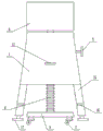
Fig. 1 is a schematic front structural view of a distribution box bracket used in a construction site according to the present invention;
fig. 2 is a schematic side structural view of a distribution box bracket used in a construction site according to the present invention;
fig. 3 is the utility model provides a block terminal support's that building site used outside structure schematic diagram.
In the figure: the device comprises a bearing box body 1, a lifting mechanism 2, a balance mechanism 3, a distribution box 4, a moving member 5, a lath 6, a universal wheel 7, a screw rod 8, a rotating rod 9, a gear 10, a bearing 11, a limit threaded rod 12, a movable hole 13, a through hole 14, a threaded hole 15, a support column 16, a support block 17, a limit screw 18, a sliding groove 19, a groove 20 and a threaded through hole 21.
Detailed Description
Referring to fig. 1-3, a block terminal support that building site used includes bearing box 1, is equipped with on the bearing box 1:
the lifting mechanism 2 is arranged on the bearing box body 1 and is used for adjusting the height of the distribution box 4;
the balance mechanism 3 is arranged at the bottom of the bearing box body 1 and used for solving the balance problem of the distribution box support under different environments;
the top of the lifting mechanism 2 is provided with a distribution box 4, and the distribution box 4 is positioned above the bearing box body 1;
the bottom of the lifting mechanism 2 is provided with a moving member 5 for moving the distribution box 4, and the moving member 5 comprises a lath 6 and a universal wheel 7.
More specifically, the lifting mechanism 2 is composed of a screw 8 movably connected with the bearing box body 1, a rotating rod 9 rotatably connected with the bearing box body 1, a gear 10 and a bearing 11 fixedly connected with the rotating rod 9, and a limit threaded rod 12 in threaded connection with the bearing box body 1, wherein a movable hole 13 matched with the screw 8 is correspondingly formed in the top and the bottom center of the bearing box body 1, a through hole 14 matched with the rotating rod 9 and a threaded hole 15 matched with the limit threaded rod 12 are formed in the side edge of the bearing box body 1, the bearing 11 is fixedly connected with the inner wall of the bearing box body 1, the gear 10 is meshed with the screw 8, the position of the limit threaded rod 12 corresponds to the position of the screw 8, the bottom end of the screw 8 is fixedly connected with the lath 6, and the top end of the part of.
More specifically, the balance mechanism 3 is composed of support columns 16 fixedly connected with four corners of the bottom of the bearing box body 1, support blocks 17 movably connected with the support columns 16, and limit screws 18 in threaded connection with the support columns 16, the support blocks 17 are non-cylindrical and are prevented from rotating, sliding grooves 19 matched with the support blocks 17 are formed in the support columns 16, threaded through holes 21 matched with the limit screws 18 are formed in the side edges of the support columns 16, and a plurality of groups of grooves 20 are formed in the support blocks 17 in a matched mode with the limit screws 18.
More specifically, there are at least two sets of universal wheel 7, prevent that the support from taking place to empty because of the fulcrum is too few, universal wheel 7 and lath 6 bottom four corners fixed connection.
More specifically, the diameter of the section of the limit threaded rod 12 is smaller than the thread pitch of the screw rod 8, so that the threaded rod 1 can clamp the screw rod 8, and a limit effect is achieved.
Now, the operation principle of the present invention is described as follows:
the utility model discloses during the use, if will remove or settle, then rotate limit threaded rod 12, make limit threaded rod 12 no longer block screw rod 8, rotate dwang 9, make gear 10 drive screw rod 8 upward or downward activity, when the support uses universal wheel 7 or supporting shoe 17 as the fulcrum, rotate limit threaded rod 12 once more, make limit line screw rod 8 block screw rod 8 again, the support can remove or settle successfully this moment, simultaneously, when the support uses supporting shoe 17 as the fulcrum, if continue to rotate dwang 9, can realize the adjustment to block terminal 4 height, when highly suitable, use limit threaded rod 12 to carry out spacing to screw rod 8 equally; when the construction site is uneven, the limiting screws 18 are rotated to ensure that the limiting screws 18 do not clamp the supporting blocks 17 any more, the supporting blocks 17 are adjusted at the moment to ensure that all the supporting blocks 17 land, the bracket is balanced, the limiting screws 18 are rotated again to ensure that the supporting blocks 17 are clamped again by the limiting screws 18, and the bracket state is fixed.
Claims (5)
1. The distribution box support used in the construction site comprises a bearing box body (1), and is characterized in that a lifting mechanism (2) and a balancing mechanism (3) are arranged on the bearing box body (1), and the lifting mechanism (2) is arranged on the bearing box body (1) and used for adjusting the height of a distribution box (4); the balance mechanism (3) is arranged at the bottom of the bearing box body (1); the top of the lifting mechanism (2) is provided with a distribution box (4), and the distribution box (4) is positioned above the bearing box body (1); lifting mechanism (2) bottom is equipped with moving member (5) and is used for removing block terminal (4), moving member (5) include lath (6) and universal wheel (7).
2. The distribution box support used at construction sites according to claim 1, wherein the lifting mechanism (2) is composed of a screw (8) movably connected with the bearing box body (1), a rotating rod (9) rotatably connected with the bearing box body (1), a gear (10) and a bearing (11) fixedly connected with the rotating rod (9), and a limit threaded rod (12) in threaded connection with the bearing box body (1), the top and the bottom center of the bearing box body (1) are correspondingly provided with a movable hole (13) matched with the screw (8), the side edge of the bearing box body (1) is provided with a through hole (14) matched with the rotating rod (9) and a threaded hole (15) matched with the limit threaded rod (12), the bearing (11) is fixedly connected with the inner wall of the bearing box body (1), the gear (10) is engaged with the screw (8), and the position of the limit threaded rod (12) corresponds to the position of the screw (8), the bottom end of the screw rod (8) is fixedly connected with the lath (6), and the screw rod (8) penetrates through the top end of the part of the top of the bearing box body (1) and is fixedly connected with the distribution box (4).
3. The distribution box support used at a construction site according to claim 1, wherein the balancing mechanism (3) is composed of support columns (16) fixedly connected with four corners of the bottom of the bearing box body (1), support blocks (17) movably connected with the support columns (16), and limit screws (18) in threaded connection with the support columns (16), sliding grooves (19) matched with the support blocks (17) are formed in the support columns (16), threaded through holes (21) matched with the limit screws (18) are formed in the side edges of the support columns (16), and a plurality of groups of grooves (20) are formed in the support blocks (17) in a matched mode with the limit screws (18).
4. The support for electric distribution boxes used at construction sites according to claim 1, characterized in that said universal wheels (7) are provided in at least two groups, said universal wheels (7) being fixedly connected to the four corners of the bottom of the lath (6).
5. A support for a distribution box used at a construction site according to claim 2, characterized in that said threaded limit rod (12) has a cross-sectional diameter smaller than the pitch of the threads of said screw (8).
Priority Applications (1)
| Application Number | Priority Date | Filing Date | Title |
|---|---|---|---|
| CN202022323074.2U CN213333435U (en) | 2020-10-19 | 2020-10-19 | Block terminal support that building site used |
Applications Claiming Priority (1)
| Application Number | Priority Date | Filing Date | Title |
|---|---|---|---|
| CN202022323074.2U CN213333435U (en) | 2020-10-19 | 2020-10-19 | Block terminal support that building site used |
Publications (1)
| Publication Number | Publication Date |
|---|---|
| CN213333435U true CN213333435U (en) | 2021-06-01 |
Family
ID=76072983
Family Applications (1)
| Application Number | Title | Priority Date | Filing Date |
|---|---|---|---|
| CN202022323074.2U Active CN213333435U (en) | 2020-10-19 | 2020-10-19 | Block terminal support that building site used |
Country Status (1)
| Country | Link |
|---|---|
| CN (1) | CN213333435U (en) |
-
2020
- 2020-10-19 CN CN202022323074.2U patent/CN213333435U/en active Active
Similar Documents
| Publication | Publication Date | Title |
|---|---|---|
| CN213391274U (en) | Adjusting device for construction and installation of steel structure steel column | |
| CN113503043A (en) | Assembly type building installation equipment | |
| CN214272856U (en) | A adjustable scaffold frame for interior decoration | |
| CN213333435U (en) | Block terminal support that building site used | |
| CN213572609U (en) | Ceiling conversion layer structure | |
| CN215548006U (en) | Adjustable depth of parallelism tool | |
| CN217151120U (en) | Novel engineering construction scaffold is built in room | |
| CN217913579U (en) | H shaped steel post gusset plate welding set | |
| CN215519976U (en) | Convenient-to-assemble template supporting device for house building | |
| CN215055289U (en) | Building templates strutting arrangement | |
| CN213215908U (en) | Drawing board strutting arrangement for architectural design | |
| CN210239082U (en) | Temporary hydropower integrated bracket for construction site | |
| CN110725316B (en) | Vertical pile cutting machine for cutting cylinders | |
| CN213387515U (en) | Small-size adjustable portal crane | |
| CN208249647U (en) | A kind of elevator arrangement device with levelling function | |
| CN210187563U (en) | Bottom fixing seat for three-dimensional rotary roller coating furnace | |
| CN220928213U (en) | Adjustable overhead building base | |
| CN207143748U (en) | One kind adjustment simply supported girder bridge holder device | |
| CN211984362U (en) | Graphic panel frame for multifunctional architectural design | |
| CN219798402U (en) | Steel structure detector | |
| CN221000099U (en) | Sock head stitching device | |
| CN213980053U (en) | Building construction strutting arrangement | |
| CN214809431U (en) | Spraying equipment for building site raise dust treatment | |
| CN221483138U (en) | Mounting platform for electromechanical installation | |
| CN219734732U (en) | Security protection control support with adjustable |
Legal Events
| Date | Code | Title | Description |
|---|---|---|---|
| GR01 | Patent grant | ||
| GR01 | Patent grant |