CN213311335U - Can regulate and control lumbar vertebrae operation and use position pad - Google Patents
Can regulate and control lumbar vertebrae operation and use position pad Download PDFInfo
- Publication number
- CN213311335U CN213311335U CN202021591206.3U CN202021591206U CN213311335U CN 213311335 U CN213311335 U CN 213311335U CN 202021591206 U CN202021591206 U CN 202021591206U CN 213311335 U CN213311335 U CN 213311335U
- Authority
- CN
- China
- Prior art keywords
- base
- pad
- lumbar vertebra
- fixedly connected
- lower limb
- Prior art date
- Legal status (The legal status is an assumption and is not a legal conclusion. Google has not performed a legal analysis and makes no representation as to the accuracy of the status listed.)
- Active
Links
Images


Abstract
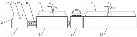
The utility model discloses a position pad for adjustable lumbar vertebra operation, which comprises a head base, a head pad, an upper limb pad, a lumbar vertebra base, a lower limb pad, an upper limb fixing band, a lower limb fixing band, a slide rail, an upper limb base and a lower limb base, wherein the head base is simultaneously connected with the slide rail in a sliding way; the upper limb base is connected with the sliding rail in a sliding manner, the upper limb pad is fixedly connected with the upper limb base, and the upper limb fixing belt is fixedly connected with the upper limb base; two ends of the lumbar vertebra base are respectively fixedly connected with the slide rail and the lower limb base; the lower limb base is fixedly connected with the lower limb pad, and the lower limb fixing band is fixedly connected with the lower limb base. Promote head and upper limbs base through the slide rail and realize position control, through elevating gear in the lumbar vertebrae pad base, according to actual conditions, highly adjust patient's lumbar vertebrae, the fixed band is all installed to upper limbs and low limbs base, can prevent effectively that patient from leading to the lumbar vertebrae to remove in the art because of uncontrollable factor, avoids the medical accident.
Description
Technical Field
The utility model belongs to the technical field of medical position pad, especially, relate to a can regulate and control lumbar vertebrae operation and use position pad.
Background
The operation position pad is a medical apparatus used in an operating room and placed on an operating table, can effectively relieve pressure sores (bedsores) caused by overlong operation time of a patient, and can be used for different position pads according to different operation positions and positions of the patient. The placement of the position of the operation is the key to the smoothness of an operation. After anesthesia, the muscle of the patient is relaxed, and the patient loses the self-ability of the whole body or the part, so the operation position not only ensures that the operation field can be fully exposed to ensure that the operation is smoothly carried out, but also takes care of the normal breathing and circulation functions of the patient to avoid the complication caused by the compression of the limb, the joint and the nerve. Therefore, the operating room needs to be assisted by some auxiliary tools to meet these requirements. Originally, operation position pad is that medical personnel use the sponge, material such as soft cloth oneself is manual to be made, though can be slight satisfy the operation demand, nevertheless because the overflow of sweat stain blood stain among the operation process, greatly reduced the bacterinertness, and the sponge is comparatively soft, and the support nature is poor, is difficult to satisfy the requirement of some operations, derive the position pad of different materials such as foaming, foam particle, inflatable after, in recent years, along with the continuous development of science and technology, the position pad of silica gel and gel material has appeared. The gel body position pad has excellent softness and supporting performance, compression resistance and shock absorption, and can disperse pressure to the maximum extent.
The height and the size of the existing body position cushion in the market are fixed values, in the actual operation process, the body types of different patients are different, most of the existing body position cushions can not be flexibly applied to various types of operations, and therefore the medical operation body position cushion with higher flexibility and adjustable position height is urgently needed to be researched and developed.
Disclosure of Invention
In order to solve the technical problem, the utility model discloses a realize through following technical scheme:
the utility model relates to an adjustable lumbar vertebra operation posture pad, which comprises a head base, a head pad, an upper limb pad, a lumbar vertebra base, a lower limb pad, an upper limb fixing band, a lower limb fixing band, a slide rail, an upper limb base and a lower limb base, wherein the head base is fixedly connected with the head pad by sewing and is also connected with the slide rail in a sliding way; the upper limb base is connected with the sliding rail in a sliding manner, the upper limb pad is fixedly connected with the upper limb base through sewing, and the upper limb fixing belt is fixedly connected with the upper limb base through screws; two ends of the lumbar vertebra base are respectively fixedly connected with the sliding rail and the lower limb base through screws; the lower limb portion base is fixedly connected with the lower limb pad through sewing, and the lower limb fixing band is fixedly connected with the lower limb portion base through screws.
As a preferred technical scheme of the utility model, the headrest left end is equipped with the forehead pillow, and the middle part is equipped with the oronasal respiration groove, and the right-hand member is equipped with the jaw pillow, and the headrest is whole to be equipped with semicircle type recess.
As an optimal technical scheme of the utility model, head pedestal mounting has the truckle, the truckle rotates with the slide rail groove in the head pedestal to be connected.
As an optimal technical scheme of the utility model, the motor is installed to the left end in the lumbar vertebrae base, the motor passes through screw fixed connection with the lumbar vertebrae base.
As an optimal technical scheme of the utility model, install the axis of rotation in the lumbar vertebrae base, the axis of rotation is connected with the motor rotation.
As an optimal technical scheme of the utility model, the axis of rotation middle part is equipped with the branch spacer block, installs first slider and second slider simultaneously, first slider and second slider pass through the screw thread rotation respectively on the both sides of dividing the spacer block and axis of rotation and are connected.
As a preferred technical scheme of the utility model, install the elevating platform in the lumbar vertebrae base, and the inner wall both sides all are equipped with the spout, first driven lever and second driven lever are installed respectively to elevating platform and spout sliding connection, elevating platform both ends, the both ends of first driven lever and second driven lever rotate with elevating platform, first slider and second slider respectively and are connected.
As a preferred technical scheme of the utility model, medical equipment is installed to the elevating platform top and is used spring and supporting pad, the both ends of spring respectively with supporting pad and elevating platform fixed connection, the supporting pad top is equipped with lumbar vertebrae pad, lumbar vertebrae pad passes through sewing mode fixed connection with the supporting pad.
The utility model discloses following beneficial effect has:
head position pad all installs on the slide rail with upper limbs position pad, different patients 'size height is all inequality, can pronate the position that each limbs actual position on the operating table adjusted head position pad and upper limbs position pad according to patient, promote head and upper limbs base through the slide rail, thereby realize position control, elevating gear height-adjusting in the lumbar vertebrae pad accessible lumbar vertebrae pad base, among the lumbar vertebrae operation process, can be according to patient actual conditions, and the operation requirement, highly adjust patient's lumbar vertebrae, make the operation field of vision have higher controllability, the fixed band is all installed to upper limbs portion and lower limbs base, can prevent effectively that patient from leading to operation in-process lumbar vertebrae to appear removing because of nervous and other uncontrollable factors, thereby avoid medical accident.
Of course, it is not necessary for any particular product to achieve all of the above-described advantages at the same time.
Drawings
In order to more clearly illustrate the technical solutions of the embodiments of the present invention, the drawings used in the description of the embodiments will be briefly introduced below, and it is obvious that the drawings in the following description are only some embodiments of the present invention, and it is obvious for those skilled in the art that other drawings can be obtained according to these drawings without creative efforts.
Fig. 1 is a schematic view of the overall structure of the present invention;
FIG. 2 is a schematic view of the cross-sectional structure of the base of the present invention;
fig. 3 is a schematic structural view of the lumbar vertebra pad of the present invention;
fig. 4 is a schematic structural diagram of the lumbar vertebra pad of the present invention at a position.
In the figure: 1. a head base; 2. a head pad; 3. an upper limb cushion; 4. a lumbar vertebra base; 5. a lower limb cushion; 6. an upper limb fixing belt; 7. a lower limb fixing strap; 8. a slide rail; 9. an upper limb base; 10. a lower limb base; 11. a frontal pillow; 12. a jaw pillow; 13. an oronasal respiratory trough; 14. a semicircular groove; 15. a small roller; 16. a motor; 17. a rotating shaft; 18. a first slider; 19. a separation block; 20. a second slider; 21. a second driven lever; 22. a first driven lever; 23. a lifting platform; 24. a chute; 25. a spring; 26. a support pad; 27. lumbar vertebra cushion.
Detailed Description
The technical solutions in the embodiments of the present invention will be described clearly and completely with reference to the accompanying drawings in the embodiments of the present invention, and it is obvious that the described embodiments are only some embodiments of the present invention, not all embodiments. Based on the embodiments of the present invention, all other embodiments obtained by a person of ordinary skill in the art without creative efforts belong to the protection scope of the present invention.
Referring to fig. 1-4, the present invention relates to a position pad for adjustable lumbar vertebra operation, which comprises a head base 1, a head pad 2, an upper limb pad 3, a lumbar vertebra base 4, a lower limb pad 5, an upper limb fixing strap 6, a lower limb fixing strap 7, a sliding rail 8, an upper limb base 9, and a lower limb base 10.
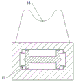
Wherein, the left end of the headrest 2 is provided with a forehead pillow 11, the middle part is provided with a mouth and nose breathing groove 13, the right end is provided with a jaw pillow 12, the whole headrest 2 is provided with a semicircular groove 14, the head base 1 is provided with a small roller 15, the small roller 15 is rotatably connected with a slide rail groove in the head base 1, the base can be pushed according to the needs of the operation process and the patient body type, and the positions of the base and the body position cushion can be adjusted.
Wherein, a motor 16 is arranged at the left end in the lumbar vertebra base 4, the motor 16 is fixedly connected with the lumbar vertebra base 4 through screws, a rotating shaft 17 is arranged in the lumbar vertebra base 4, the rotating shaft 17 is rotatably connected with the motor 16, a separation block 19 is arranged in the middle of the rotating shaft 17, a first slide block 18 and a second slide block 20 are simultaneously arranged, the first slide block 18 and the second slide block 20 are respectively rotatably connected with the rotating shaft 17 through threads at two sides of the separation block 19, a lifting table 23 is arranged in the lumbar vertebra base 4, slide grooves 24 are respectively arranged at two sides of the inner wall, the lifting table 23 is slidably connected with the slide grooves 24, a first driven rod 22 and a second driven rod 21 are respectively arranged at two ends of the lifting table 23, two ends of the first driven rod 22 and the second driven rod 21 are respectively rotatably connected with the lifting table 23, the first slide block 18 and the second slide block 20, a spring 25 and a supporting pad 26 for medical equipment are arranged above the lifting table 23, two ends, supporting pad 26 top is equipped with lumbar vertebrae pad 27, and lumbar vertebrae pad 27 passes through sewing mode fixed connection with supporting pad 26, rotates through motor 16 control axis of rotation 17 to remove about making the slider through reverse screw, promote the follower lever, make supporting pad 26 and lumbar vertebrae pad 27 of installing on elevating platform 23 realize the lift action, thereby realize adjusting lumbar vertebrae operation position height.
Finally, it should be noted that: in the description of the present invention, it should be noted that the terms "vertical", "upper", "lower", "horizontal", and the like indicate orientations or positional relationships based on the orientations or positional relationships shown in the drawings, and are only for convenience of description and simplification of description, but do not indicate or imply that the device or element referred to must have a specific orientation, be constructed in a specific orientation, and be operated, and thus should not be construed as limiting the present invention.
In the description herein, references to the description of "one embodiment," "an example," "a specific example," etc., mean that a particular feature, structure, material, or characteristic described in connection with the embodiment or example is included in at least one embodiment or example of the invention. In this specification, the schematic representations of the terms used above do not necessarily refer to the same embodiment or example. Furthermore, the particular features, structures, materials, or characteristics described may be combined in any suitable manner in any one or more embodiments or examples.
The preferred embodiments of the present invention disclosed above are intended only to help illustrate the present invention. The preferred embodiments are not intended to be exhaustive or to limit the invention to the precise embodiments disclosed. Obviously, many modifications and variations are possible in light of the above teaching. The embodiments were chosen and described in order to best explain the principles of the invention and its practical applications, to thereby enable others skilled in the art to best understand the invention for and utilize the invention. The present invention is limited only by the claims and their full scope and equivalents.
Claims (8)
1. An adjustable lumbar vertebra operation posture pad comprises a head base (1), a headrest (2), an upper limb pad (3), a lumbar vertebra base (4), a lower limb pad (5), an upper limb fixing band (6), a lower limb fixing band (7), a sliding rail (8), an upper limb base (9) and a lower limb base (10), and is characterized in that the head base (1) is fixedly connected with the headrest (2) in a sewing manner and is also connected with the sliding rail (8) in a sliding manner; the upper limb base (9) is connected with the sliding rail (8) in a sliding manner, the upper limb pad (3) is fixedly connected with the upper limb base (9) through sewing, and the upper limb fixing belt (6) is fixedly connected with the upper limb base (9) through screws; two ends of the lumbar vertebra base (4) are respectively fixedly connected with the sliding rail (8) and the lower limb base (10) through screws; the lower limb portion base (10) is fixedly connected with the lower limb pad (5) through sewing, and the lower limb fixing belt (7) is fixedly connected with the lower limb portion base (10) through screws.
2. The adjustable posture pad for lumbar vertebra surgery as claimed in claim 1, wherein the headrest (11) is arranged at the left end of the headrest (2), the mouth-nose breathing groove (13) is arranged in the middle of the headrest, the jaw pillow (12) is arranged at the right end of the headrest, and the semicircular groove (14) is integrally formed in the headrest (2).
3. The adjustable posture pad for lumbar vertebra surgery as claimed in claim 1, wherein the head base (1) is provided with a small roller (15), and the small roller (15) is rotatably connected with a slide rail groove in the head base (1).
4. The adjustable posture pad for lumbar vertebra surgery as claimed in claim 1, wherein a motor (16) is installed at the left end of the interior of the lumbar vertebra base (4), and the motor (16) is fixedly connected with the lumbar vertebra base (4) through screws.
5. The adjustable posture pad for lumbar vertebra surgery as recited in claim 1, characterized in that a rotating shaft (17) is installed in the lumbar vertebra base (4), and the rotating shaft (17) is rotatably connected with a motor (16).
6. The adjustable posture pad for lumbar surgery as recited in claim 5, characterized in that a separation block (19) is provided in the middle of the rotation shaft (17), and a first slide block (18) and a second slide block (20) are installed at the same time, and the first slide block (18) and the second slide block (20) are respectively connected with the rotation shaft (17) at two sides of the separation block (19) through screw threads in a rotating manner.
7. The adjustable posture pad for lumbar vertebra surgery as defined in claim 1, wherein a lifting table (23) is installed in the lumbar vertebra base (4), and sliding grooves (24) are formed on both sides of the inner wall, the lifting table (23) is slidably connected with the sliding grooves (24), a first driven rod (22) and a second driven rod (21) are respectively installed at both ends of the lifting table (23), and both ends of the first driven rod (22) and the second driven rod (21) are respectively rotatably connected with the lifting table (23), the first sliding block (18) and the second sliding block (20).
8. The adjustable posture pad for lumbar vertebra surgery as claimed in claim 7, wherein a spring (25) and a support pad (26) for medical equipment are installed above the lifting platform (23), two ends of the spring (25) are respectively fixedly connected with the support pad (26) and the lifting platform, a lumbar cushion (27) is arranged above the support pad (26), and the lumbar cushion (27) is fixedly connected with the support pad (26) through sewing.
Priority Applications (1)
| Application Number | Priority Date | Filing Date | Title |
|---|---|---|---|
| CN202021591206.3U CN213311335U (en) | 2020-08-04 | 2020-08-04 | Can regulate and control lumbar vertebrae operation and use position pad |
Applications Claiming Priority (1)
| Application Number | Priority Date | Filing Date | Title |
|---|---|---|---|
| CN202021591206.3U CN213311335U (en) | 2020-08-04 | 2020-08-04 | Can regulate and control lumbar vertebrae operation and use position pad |
Publications (1)
| Publication Number | Publication Date |
|---|---|
| CN213311335U true CN213311335U (en) | 2021-06-01 |
Family
ID=76093414
Family Applications (1)
| Application Number | Title | Priority Date | Filing Date |
|---|---|---|---|
| CN202021591206.3U Active CN213311335U (en) | 2020-08-04 | 2020-08-04 | Can regulate and control lumbar vertebrae operation and use position pad |
Country Status (1)
| Country | Link |
|---|---|
| CN (1) | CN213311335U (en) |
-
2020
- 2020-08-04 CN CN202021591206.3U patent/CN213311335U/en active Active
Similar Documents
| Publication | Publication Date | Title |
|---|---|---|
| CN110338916B (en) | Head fixing device for neurosurgery department | |
| CN213311335U (en) | Can regulate and control lumbar vertebrae operation and use position pad | |
| CN210330849U (en) | Four-dimensional cervical vertebra traction bed | |
| CN209864493U (en) | Neck anesthesia auxiliary device in operating room | |
| CN208160723U (en) | acupuncture bed | |
| CN214550575U (en) | Airway opening auxiliary device | |
| CN214858544U (en) | Prone position pillow for ophthalmologic nursing | |
| CN215229578U (en) | Fixing device for orthopedics | |
| CN214105067U (en) | But operating room is with angle regulation's position pad | |
| CN210301624U (en) | Adjustable lumbar vertebrae operation position pad | |
| CN208989525U (en) | A kind of liftable operating bed in head | |
| CN112451291A (en) | Orthopedics sick bed nursing support | |
| CN214415190U (en) | Face protection gel supporting pad for prone position operation patient | |
| CN216365792U (en) | Fixing frame for shoulder support, waist support and side position on operating table | |
| CN217938577U (en) | Postoperative care frame for retinal detachment | |
| CN214018354U (en) | Spinal surgery pad | |
| CN213851781U (en) | Novel body position pad for thyroid surgery | |
| CN219579284U (en) | Prone position ventilation mattress with adjustable height | |
| CN216536010U (en) | Prone position operation patient uses headrest | |
| CN216962660U (en) | Auxiliary frame for orthopedic operation | |
| CN215425819U (en) | Combined type body position pad for operating room | |
| CN219071042U (en) | Shoulder joint bolster | |
| CN213250629U (en) | Severe nursing pillow | |
| CN219921469U (en) | Automatic prevent pressing sore prone position headstock | |
| CN219439871U (en) | Spinal surgery support |
Legal Events
| Date | Code | Title | Description |
|---|---|---|---|
| GR01 | Patent grant | ||
| GR01 | Patent grant |