CN213258679U - Grinding device is used in metal work piece processing - Google Patents
Grinding device is used in metal work piece processing Download PDFInfo
- Publication number
- CN213258679U CN213258679U CN202022371218.1U CN202022371218U CN213258679U CN 213258679 U CN213258679 U CN 213258679U CN 202022371218 U CN202022371218 U CN 202022371218U CN 213258679 U CN213258679 U CN 213258679U
- Authority
- CN
- China
- Prior art keywords
- plates
- fixedly arranged
- sliding connection
- lateral plates
- concave frame
- Prior art date
- Legal status (The legal status is an assumption and is not a legal conclusion. Google has not performed a legal analysis and makes no representation as to the accuracy of the status listed.)
- Expired - Fee Related
Links
Images


Abstract
The utility model provides a grinding device is used in metal work piece processing. The polishing device for processing the metal workpiece comprises a workbench; the two lateral plates are fixedly arranged at the top of the workbench; the two first air cylinders are fixedly arranged on one sides, close to the two lateral plates, of the two lateral plates respectively; the two push plates are respectively and fixedly arranged on the output shafts of the two first air cylinders; the second air cylinder is arranged between the two lateral plates; the concave frame is arranged between the two lateral plates, and the top of the concave frame is fixedly connected with an output shaft of the second air cylinder; the lead screw is rotatably arranged on the inner walls of the two sides of the concave frame. The utility model provides a grinding device is used in metal work piece processing has need not manually to get the material, reduce physical expenditure, reduce intensity of labour, the higher advantage of convenience.
Description
Technical Field
The utility model relates to a metalwork processing technology field especially relates to a grinding device is used in metal work processing.
Background
Polishing is one of surface modification techniques, generally refers to a processing method for changing physical properties of a material surface by friction with the aid of a rough object, and is mainly used for obtaining specific surface roughness.
However, when the traditional polishing device is used, people need to continuously take out and place workpieces at polishing positions, but because metal workpieces are heavy in mass, the work fatigue is accelerated in the long-time continuous taking process of people, and the heavy metal workpieces also greatly increase the labor intensity and are inconvenient to use.
Therefore, there is a need to provide a new grinding device for machining metal workpieces to solve the above technical problems.
SUMMERY OF THE UTILITY MODEL
The utility model provides a technical problem provide a need not manually to get the material, reduce physical expenditure, reduce intensity of labour, the higher grinding device for metal work processing of convenience.
In order to solve the technical problem, the utility model provides a grinding device for metal work piece processing includes: a work table; the two lateral plates are fixedly arranged at the top of the workbench; the two first air cylinders are fixedly arranged on one sides, close to the two lateral plates, of the two lateral plates respectively; the two push plates are respectively and fixedly arranged on the output shafts of the two first air cylinders; the second air cylinder is arranged between the two lateral plates; the concave frame is arranged between the two lateral plates, and the top of the concave frame is fixedly connected with an output shaft of the second air cylinder; the screw rods are rotatably arranged on the inner walls of the two sides of the concave frame; the first motor is fixedly arranged on the outer wall of one side of the concave frame; the sliding connection seat is installed on the lead screw in a threaded manner; the polishing mechanism is fixedly arranged at the bottom of the sliding connection seat; the two vertical plates are fixedly arranged at the bottom of the workbench; the bearing seat is fixedly arranged on one side of the two vertical plates close to each other; the material passing port is formed in the top of the workbench; the bearing plate is arranged in the material through opening and is matched with the material through opening; the joint block is fixedly arranged at the bottom of the bearing plate, and the bottom of the joint block extends to the position below the workbench; a hollow column hinged to the junction block; the adjusting screw rod is rotatably installed at the top of the bearing seat, and the top end of the adjusting screw rod extends into the hollow column and is in threaded connection with the inner wall of the bottom of the hollow column; the second motor is fixedly installed at the bottom of the bearing seat, and an output shaft of the second motor is fixedly connected with the bottom end of the adjusting screw rod; the sliding connection block is arranged at the bottom of the bearing plate in a sliding manner; and the third cylinder is arranged below the bearing plate, and an output shaft of the third cylinder is hinged with the sliding connection block.
Preferably, one side of each of the two lateral plates, which is close to each other, is fixedly provided with the same transverse plate, and the bottom of the transverse plate is fixedly connected with the second cylinder.
Preferably, two the equal fixed mounting in one side that the push pedal is close to each other has a plurality of anti-skidding conical heads, two the equal fixed mounting in one side that the push pedal was kept away from each other has branch, two the one end that branch was kept away from each other runs through two respectively the side direction board and with correspond side direction board sliding connection.
Preferably, fixed mounting has a gag lever post on the both sides inner wall of concave shape frame, the gag lever post runs through sliding connection seat and with sliding connection seat sliding connection, fixed mounting has two baffles on the top inner wall of concave shape frame, the lead screw runs through the baffle and with baffle swing joint, the gag lever post runs through the baffle and with baffle swing joint.
Preferably, a material receiving box is fixedly installed at the top of the bearing seat, and the material receiving box is matched with the bearing plate.
Preferably, a connection table is fixedly installed on the outer wall of one side of the hollow column, and the top of the connection table is fixedly connected with the cylinder III.
Preferably, a clamping plate is fixedly installed at the top end of the adjusting screw rod.
Compared with the prior art, the utility model provides a grinding device for metal work piece processing has following beneficial effect:
the utility model provides a polishing device for processing metal workpieces, when polishing, the output shafts of two cylinders I are started to extend to reliably clamp the metal workpieces, then the output shaft of a cylinder II is started to extend to enable a polishing mechanism to contact with workpieces, then a motor I is started to horizontally polish the metal workpieces, after polishing is finished, the output shaft of the cylinder I is started to retract, the output shaft of the cylinder II retracts, then a motor II is started in a forward direction to enable a hollow column to descend with a bearing plate, then the output shaft of a cylinder III is started to extend to enable the bearing plate to be in an inclined state, the metal workpieces on the cylinder III automatically slide into a material receiving box, then the output shaft of the cylinder III retracts, and the motor II is started in a reverse direction to enable the bearing plate to ascend to an initial position, next polishing work can be carried out, and through an automatic material sliding process, the metal workpiece does not need to be manually taken in the material taking process, so that the physical expenditure is greatly reduced, the labor intensity is reduced, and the overall convenience is improved.
Drawings
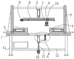
Fig. 1 is a schematic structural view of a polishing device for machining a metal workpiece according to a preferred embodiment of the present invention;
FIG. 2 is an enlarged view of portion A of FIG. 1;
fig. 3 is a schematic side view of the connecting structure between the workbench and the load-bearing seat shown in fig. 1.
Reference numbers in the figures: 1. a work table; 2. a lateral plate; 3. a first cylinder; 4. pushing the plate; 5. a second air cylinder; 6. a concave frame; 7. a lead screw; 8. a first motor; 9. a sliding connection seat; 10. a polishing mechanism; 11. a vertical plate; 12. a load bearing seat; 13. a material inlet is formed; 14. a bearing plate; 15. a joining block; 16. a hollow column; 17. adjusting the screw rod; 18. a second motor; 19. a sliding connection block; 20. and a third air cylinder.
Detailed Description
The present invention will be further described with reference to the accompanying drawings and embodiments.
Please refer to fig. 1, fig. 2 and fig. 3, wherein fig. 1 is a schematic structural diagram of a polishing device for processing a metal workpiece according to a preferred embodiment of the present invention; FIG. 2 is an enlarged view of portion A of FIG. 1; fig. 3 is a schematic side view of the connecting structure between the workbench and the load-bearing seat shown in fig. 1. Grinding device for metal workpiece processing includes: a work table 1; the two lateral plates 2 are fixedly arranged at the top of the workbench 1; the two cylinders I3 are respectively and fixedly arranged on one sides, close to each other, of the two lateral plates 2; the two push plates 4 are respectively and fixedly arranged on the output shafts of the two cylinders I3; a second air cylinder 5, wherein the second air cylinder 5 is arranged between the two lateral plates 2; the concave frame 6 is arranged between the two lateral plates 2, and the top of the concave frame 6 is fixedly connected with an output shaft of the second cylinder 5; the lead screw 7 is rotatably arranged on the inner walls of the two sides of the concave frame 6; the motor I8 is fixedly arranged on the outer wall of one side of the concave frame 6; the sliding connection seat 9 is installed on the lead screw 7 in a threaded mode; the polishing mechanism 10 is fixedly arranged at the bottom of the sliding connection seat 9; the two vertical plates 11 are fixedly arranged at the bottom of the workbench 1; the bearing seat 12 is fixedly arranged on one side of the two vertical plates 11, which are close to each other; the material passing port 13 is formed in the top of the workbench 1; the bearing plate 14 is arranged in the material passing port 13, and the bearing plate 14 is matched with the material passing port 13; the joint block 15 is fixedly arranged at the bottom of the bearing plate 14, and the bottom of the joint block 15 extends to the lower part of the workbench 1; a hollow column 16, said hollow column 16 being hinged to said adapter block 15; the adjusting screw 17 is rotatably installed at the top of the bearing seat 12, and the top end of the adjusting screw 17 extends into the hollow column 16 and is in threaded connection with the inner wall of the bottom of the hollow column 16; the second motor 18 is fixedly installed at the bottom of the bearing seat 12, and an output shaft of the second motor 18 is fixedly connected with the bottom end of the adjusting screw rod 17; the sliding connection block 19 is arranged at the bottom of the bearing plate 14 in a sliding mode; and the third air cylinder 20 is arranged below the bearing plate 14, and an output shaft of the third air cylinder 20 is hinged with the sliding block 19.
And one side of each lateral plate 2, which is close to each other, is fixedly provided with the same transverse plate, and the bottom of the transverse plate is fixedly connected with the second cylinder 5.
Two equal fixed mounting in one side that push pedal 4 is close to each other has a plurality of anti-skidding conical heads, two equal fixed mounting in one side that push pedal 4 kept away from each other has branch, two the one end that branch kept away from each other runs through two respectively side direction board 2 and with correspond side direction board 2 sliding connection.
Fixed mounting has a gag lever post on the both sides inner wall of concave frame 6, the gag lever post runs through sliding connection seat 9 and with sliding connection seat 9 sliding connection, fixed mounting has two baffles on the top inner wall of concave frame 6, lead screw 7 runs through the baffle and with baffle swing joint, the gag lever post runs through the baffle and with baffle swing joint.
And a material receiving box is fixedly arranged at the top of the bearing seat 12 and is matched with the bearing plate 14.
And a connecting table is fixedly installed on the outer wall of one side of the hollow column 16, and the top of the connecting table is fixedly connected with the third cylinder 20.
And a clamping plate is fixedly arranged at the top end of the adjusting screw rod 17.
The utility model provides a grinding device is used in metal work piece processing's theory of operation as follows:
when the polishing mechanism 10 is used, a metal workpiece is placed at the top of the bearing plate 14, then the output shafts of the two cylinders I3 are started to extend out, so that the two push plates 4 are close to each other, the anti-skid conical heads on the push plates 4 are enabled to contact the metal workpiece and reliably clamp the metal workpiece, then the output shafts of the cylinders II 5 are started to extend out, the concave frame 6 is enabled to descend, and after the polishing mechanism 10 contacts the workpiece, the motors I8 are started to enable the lead screws 7 to rotate, so that the sliding connection seat 9 drives the polishing mechanism 10 to horizontally displace, and then the metal workpiece is polished;
after polishing, the output shaft of the first cylinder 3 retracts, the output shaft of the second cylinder 5 retracts, metal workpieces are not limited at this time, then the second motor 18 is started in a forward direction, the adjusting screw 17 can be driven to rotate, the hollow column 16 with the bearing plate 14 descends, meanwhile, the metal workpieces located above the bearing plate 14 also descend, until the metal workpieces descend to the maximum position, the output shaft of the third cylinder 20 is started to extend out, the bearing plate 14 can make circular motion by taking the hinged position of the connecting block 15 as a circle center, the bearing plate 14 is in an inclined state, the metal workpieces on the bearing plate can automatically slide into the material receiving box, then the output shaft of the third cylinder 20 retracts, and then the second motor 18 is started in a reverse direction, so that the bearing plate 14 ascends to the initial position, and next polishing work can be carried out.
Compared with the prior art, the utility model provides a grinding device for metal work piece processing has following beneficial effect:
the utility model provides a grinding device for processing metal workpieces, when grinding, the output shaft of two cylinders I3 is started to extend, the metal workpieces are reliably clamped tightly, then the output shaft of a cylinder II 5 is started to extend, a grinding mechanism 10 is made to contact with the workpieces, then a motor I8 is started, horizontal grinding work can be carried out on the metal workpieces, after grinding is finished, the output shaft of the cylinder I3 is started to retract, the output shaft of the cylinder II 5 retracts, then a motor II 18 is started in a forward direction, a hollow column 16 with a bearing plate 14 descends, then the output shaft of the cylinder III 20 is started to extend, the bearing plate 14 is in an inclined state, the metal workpieces on the bearing plate automatically slide into a material receiving box, then the output shaft of the cylinder III 20 retracts, the motor II 18 is started in a reverse direction, the bearing plate 14 ascends to an initial position, and next grinding work can be carried out, through the automatic material sliding process, the metal workpiece does not need to be manually taken in the material taking process, the physical expenditure is greatly reduced, the labor intensity is reduced, and the overall convenience is improved.
The above only is the embodiment of the present invention, not limiting the scope of the present invention, all the equivalent structures or equivalent processes of the present invention are used in the specification and the attached drawings, or directly or indirectly applied to other related technical fields, and the same principle is included in the protection scope of the present invention.
Claims (7)
1. The utility model provides a grinding device is used in metal work piece processing which characterized in that includes:
a work table;
the two lateral plates are fixedly arranged at the top of the workbench;
the two first air cylinders are fixedly arranged on one sides, close to the two lateral plates, of the two lateral plates respectively;
the two push plates are respectively and fixedly arranged on the output shafts of the two first air cylinders;
the second air cylinder is arranged between the two lateral plates;
the concave frame is arranged between the two lateral plates, and the top of the concave frame is fixedly connected with an output shaft of the second air cylinder;
the screw rods are rotatably arranged on the inner walls of the two sides of the concave frame;
the first motor is fixedly arranged on the outer wall of one side of the concave frame;
the sliding connection seat is installed on the lead screw in a threaded manner;
the polishing mechanism is fixedly arranged at the bottom of the sliding connection seat;
the two vertical plates are fixedly arranged at the bottom of the workbench;
the bearing seat is fixedly arranged on one side of the two vertical plates close to each other;
the material passing port is formed in the top of the workbench;
the bearing plate is arranged in the material through opening and is matched with the material through opening;
the joint block is fixedly arranged at the bottom of the bearing plate, and the bottom of the joint block extends to the position below the workbench;
a hollow column hinged to the junction block;
the adjusting screw rod is rotatably installed at the top of the bearing seat, and the top end of the adjusting screw rod extends into the hollow column and is in threaded connection with the inner wall of the bottom of the hollow column;
the second motor is fixedly installed at the bottom of the bearing seat, and an output shaft of the second motor is fixedly connected with the bottom end of the adjusting screw rod;
the sliding connection block is arranged at the bottom of the bearing plate in a sliding manner;
and the third cylinder is arranged below the bearing plate, and an output shaft of the third cylinder is hinged with the sliding connection block.
2. The grinding device for machining the metal workpiece according to claim 1, wherein the same transverse plate is fixedly installed on one side, close to each other, of the two lateral plates, and the bottom of the transverse plate is fixedly connected with the second air cylinder.
3. The polishing device for processing the metal workpiece as claimed in claim 1, wherein a plurality of anti-slip conical heads are fixedly mounted on the sides of the two pushing plates close to each other, supporting rods are fixedly mounted on the sides of the two pushing plates far away from each other, and the ends of the two supporting rods far away from each other respectively penetrate through the two lateral plates and are slidably connected with the corresponding lateral plates.
4. The polishing device for processing the metal workpiece as recited in claim 1, wherein limiting rods are fixedly mounted on inner walls of two sides of the concave frame, the limiting rods penetrate through the sliding connection seat and are in sliding connection with the sliding connection seat, two baffle plates are fixedly mounted on an inner wall of the top of the concave frame, the screw rod penetrates through the baffle plates and is movably connected with the baffle plates, and the limiting rods penetrate through the baffle plates and are movably connected with the baffle plates.
5. The grinding device for machining the metal workpiece according to claim 1, wherein a material receiving box is fixedly mounted at the top of the bearing seat, and the material receiving box is matched with the bearing plate.
6. The grinding device for processing the metal workpiece according to claim 1, wherein a connecting table is fixedly arranged on the outer wall of one side of the hollow column, and the top of the connecting table is fixedly connected with the cylinder III.
7. The grinding device for machining a metal workpiece as set forth in claim 1, wherein a clamping plate is fixedly mounted to a top end of the adjusting screw.
Priority Applications (1)
| Application Number | Priority Date | Filing Date | Title |
|---|---|---|---|
| CN202022371218.1U CN213258679U (en) | 2020-10-22 | 2020-10-22 | Grinding device is used in metal work piece processing |
Applications Claiming Priority (1)
| Application Number | Priority Date | Filing Date | Title |
|---|---|---|---|
| CN202022371218.1U CN213258679U (en) | 2020-10-22 | 2020-10-22 | Grinding device is used in metal work piece processing |
Publications (1)
| Publication Number | Publication Date |
|---|---|
| CN213258679U true CN213258679U (en) | 2021-05-25 |
Family
ID=75950711
Family Applications (1)
| Application Number | Title | Priority Date | Filing Date |
|---|---|---|---|
| CN202022371218.1U Expired - Fee Related CN213258679U (en) | 2020-10-22 | 2020-10-22 | Grinding device is used in metal work piece processing |
Country Status (1)
| Country | Link |
|---|---|
| CN (1) | CN213258679U (en) |
-
2020
- 2020-10-22 CN CN202022371218.1U patent/CN213258679U/en not_active Expired - Fee Related
Similar Documents
| Publication | Publication Date | Title |
|---|---|---|
| CN212371092U (en) | Clamping and rotating device for forging processing | |
| CN112846874A (en) | Rapid fixing clamp for aluminum alloy machining | |
| CN210388671U (en) | Engineering machine tool accessory grinding device with adjustable interval | |
| CN209812004U (en) | Spinneret plate surface treatment device | |
| CN212496556U (en) | Clamping tool for machining metal workpiece | |
| CN213258679U (en) | Grinding device is used in metal work piece processing | |
| CN219211297U (en) | Automatic rotating device for flange plate stamping | |
| CN217143327U (en) | Numerical control lathe axle class work piece grinding device | |
| CN212886345U (en) | Machining device for numerical control machine tool | |
| CN213259132U (en) | Mechanical clamp | |
| CN212706313U (en) | Portable fixture tool | |
| CN211490956U (en) | Automatic polishing and grinding machine for aluminum profiles | |
| CN209754604U (en) | Clamping device for machine tool machining | |
| CN213470404U (en) | Quick right angle clamping tool | |
| CN113510596B (en) | Feeding mechanism of polishing machine for bolt machining | |
| CN111136599A (en) | Pneumatic clamping jig for die machining | |
| CN111015292A (en) | Multi-angle adjusting clamp for machine tool and using method thereof | |
| CN218696174U (en) | Die machining groove | |
| CN216577386U (en) | Hydraulic bench clamp | |
| CN211386390U (en) | Quick straightener of broach | |
| CN214721056U (en) | Vertical broaching machine for machining bearing inner ring | |
| CN218776358U (en) | Aluminum alloy cabinet body processing polishing equipment | |
| CN218427270U (en) | Clamp structure for automatic machining of pulley shaft of crane | |
| CN218382042U (en) | Screw quality detection device | |
| CN210435864U (en) | Five metals stamping workpiece burr treatment equipment |
Legal Events
| Date | Code | Title | Description |
|---|---|---|---|
| GR01 | Patent grant | ||
| GR01 | Patent grant | ||
| CF01 | Termination of patent right due to non-payment of annual fee | ||
| CF01 | Termination of patent right due to non-payment of annual fee |
Granted publication date: 20210525 Termination date: 20211022 |