CN212706313U - Portable fixture tool - Google Patents
Portable fixture tool Download PDFInfo
- Publication number
- CN212706313U CN212706313U CN202021196729.8U CN202021196729U CN212706313U CN 212706313 U CN212706313 U CN 212706313U CN 202021196729 U CN202021196729 U CN 202021196729U CN 212706313 U CN212706313 U CN 212706313U
- Authority
- CN
- China
- Prior art keywords
- block
- connecting rod
- spring
- driving wheel
- bolt
- Prior art date
- Legal status (The legal status is an assumption and is not a legal conclusion. Google has not performed a legal analysis and makes no representation as to the accuracy of the status listed.)
- Expired - Fee Related
Links
- 238000003466 welding Methods 0.000 claims abstract description 7
- 230000007246 mechanism Effects 0.000 claims description 6
- 238000003825 pressing Methods 0.000 abstract description 6
- 230000009471 action Effects 0.000 abstract description 5
- 238000010276 construction Methods 0.000 abstract description 2
- 244000309464 bull Species 0.000 description 5
- 230000002349 favourable effect Effects 0.000 description 5
- 238000006073 displacement reaction Methods 0.000 description 2
- 238000004519 manufacturing process Methods 0.000 description 2
- 230000004075 alteration Effects 0.000 description 1
- 230000009286 beneficial effect Effects 0.000 description 1
- 238000003754 machining Methods 0.000 description 1
- 238000012986 modification Methods 0.000 description 1
- 230000004048 modification Effects 0.000 description 1
- 230000001737 promoting effect Effects 0.000 description 1
- 238000006467 substitution reaction Methods 0.000 description 1
Images


Landscapes
- Conveying And Assembling Of Building Elements In Situ (AREA)
Abstract
The utility model discloses a portable fixture tool, including base and stop gear, the spout has been seted up in the base outside, and the spout outside is connected with the slider, and settle the slider top has the ejector pad, and ejector pad one side is provided with the pivot, pivot one side is connected with the bolt, and the outside arrangement of bolt has the stopper, the base top is fixed with supports the piece, and supports the inside action wheel that is provided with of piece, the action wheel outside is connected with from the driving wheel. This portable fixture attachment installs stop gear, the connecting rod constitutes elastic construction between through first spring and supporting shoe, and the connecting rod is "L" type, make things convenient for the fixed block after the fixed part, through loosening the connecting rod, make it recover through the elasticity of first spring, make the fixture block on connecting rod surface block in the draw-in groove of supporting shoe internal surface, thereby fix the fixed block after fixing, and constitute welding integrated structure between connecting rod and the fixture block, and the fixture block is the slope structure, the stability of pressing of anchor clamps has been strengthened greatly.
Description
Technical Field
The utility model relates to an anchor clamps frock technical field specifically is a portable anchor clamps frock.
Background
Along with urgent continuous development of society now, people's standard of living also is constantly promoting, and people also more and more high to the level requirement of production facility, the frock on the tooling equipment, technological equipment promptly: the tool is a general name of various tools used in the manufacturing process, including a cutter/clamp/mould/measuring tool/detecting tool/auxiliary tool/bench tool/station tool and the like, and the tool is a general abbreviation thereof.
The clamp tooling structure on the market is complex at present, the use is inconvenient, the part tool after the clamping is fixed is difficult to keep the stability, the general clamp can only carry out the clamping in one position to the part tool, the condition of displacement is easily caused in the machining process, and a portable clamp tooling is provided aiming at the condition.
SUMMERY OF THE UTILITY MODEL
An object of the utility model is to provide a portable fixture attachment to it is comparatively complicated to provide general fixture attachment structure in solving above-mentioned background art, and it is very inconvenient to use, and the part instrument after the centre gripping is fixed is difficult to keep its stability, and general anchor clamps can only carry out the centre gripping in a position to it, leads to the problem that takes place the displacement in the course of working easily.
In order to achieve the above object, the utility model provides a following technical scheme: the utility model provides a portable fixture tool, includes base and stop gear, the spout has been seted up in the base outside, and the spout outside is connected with the slider, settle the slider top has the ejector pad, and ejector pad one side is provided with the pivot, pivot one side is connected with the bolt, and the outside arrangement of bolt has the stopper, the base top is fixed with to the piece, and supports the inside action wheel that is provided with of piece, the action wheel outside is connected with from the driving wheel, and is provided with the bull stick from the driving wheel outside, the terminal arrangement of bull stick has the fixed block, the action wheel below is provided with the pull rod, and the notch has been seted up on the pull rod surface.
Preferably, the push block forms a sliding structure through the sliding block and the sliding groove, and the push block forms a movable structure through the bolt and the limiting block.
Preferably, the rotating rod is movably connected with the driving wheel through the driven wheel, and the outer surface of the driving wheel is attached to the outer surface of the driven wheel.
Preferably, notches are uniformly distributed on the surface of the pull rod, and the size of an inner opening of each notch is matched with that of an outer opening of the driving wheel.
Preferably, the limiting mechanism comprises a connecting rod, a first spring, a second spring, a clamping block, a supporting block and a clamping groove, the first spring is arranged below the connecting rod, the second spring is connected to the tail end of the connecting rod, the clamping block is arranged on the surface of the connecting rod, the supporting block is arranged outside the connecting rod, and the clamping groove is formed in the inner surface of the supporting block.
Preferably, the connecting rod forms an elastic structure with the supporting block through the first spring, and the connecting rod is L-shaped.
Preferably, a welding integrated structure is formed between the connecting rod and the clamping block, and the clamping block is of an inclined structure.
Compared with the prior art, the beneficial effects of the utility model are that:
the portable fixture tool is provided with the push block, the push block forms a sliding structure through the sliding block and the sliding groove, the push block can slide on the sliding groove on the outer side of the base through the sliding block, the push block forms a movable structure through the bolt and the limiting block, the push block can move left and right through the limiting block through rotating the bolt, and therefore the push block at the tail end of the bolt is driven to slide on the sliding groove, and the push block is matched with the abutting block to transversely clamp and fix a part;
the portable fixture tool is provided with the rotating rod, the rotating rod is movably connected with the driving wheel through the driven wheel, the driving wheel is favorable for driving the rotating rod outside the driven wheel to rotate through rotation, the tail end of the rotating rod is provided with the fixed block, the fixed block can conveniently press parts fixed by the push block and the abutting block, and the parts can keep vertical stability during processing;
this portable fixture attachment installs stop gear, the connecting rod constitutes elastic construction between through first spring and supporting shoe, and the connecting rod is "L" type, make things convenient for the fixed block after the fixed part, through loosening the connecting rod, make it recover through the elasticity of first spring, and make the fixture block on connecting rod surface block in the draw-in groove of supporting shoe internal surface, thereby fix the fixed block after fixing, and constitute welding integrated structure between connecting rod and the fixture block, and the fixture block is the slope structure, the stability of pressing of anchor clamps has been strengthened greatly.
Drawings
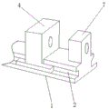
FIG. 1 is a schematic view of the structure of the present invention;
FIG. 2 is a schematic view of the push block structure of the present invention;
fig. 3 is an enlarged schematic view of a portion a in fig. 1 according to the present invention.
In the figure: 1. a base; 2. a chute; 3. a slider; 4. a push block; 5. a rotating shaft; 6. a bolt; 7. a limiting block; 8. a resisting block; 9. a driving wheel; 10. a driven wheel; 11. a rotating rod; 12. a fixed block; 13. a pull rod; 14. a notch; 15. a limiting mechanism; 1501. a connecting rod; 1502. a first spring; 1503. a second spring; 1504. a clamping block; 1505. a support block; 1506. a clamping groove.
Detailed Description
The technical solutions in the embodiments of the present invention will be described clearly and completely with reference to the accompanying drawings in the embodiments of the present invention, and it is obvious that the described embodiments are only some embodiments of the present invention, not all embodiments. Based on the embodiments in the present invention, all other embodiments obtained by a person skilled in the art without creative work belong to the protection scope of the present invention.
Referring to fig. 1-3, the present invention provides a technical solution: a portable fixture tool comprises a base 1 and a limiting mechanism 15, wherein a sliding groove 2 is formed in the outer side of the base 1, a sliding block 3 is connected to the outer side of the sliding groove 2, a pushing block 4 is arranged above the sliding block 3, a rotating shaft 5 is arranged on one side of the pushing block 4, a bolt 6 is connected to one side of the rotating shaft 5, a limiting block 7 is arranged outside the bolt 6, the pushing block 4 forms a sliding structure with the sliding groove 2 through the sliding block 3, the pushing block 4 forms a movable structure with the limiting block 7 through the bolt 6, the pushing block 4 is favorable for sliding on the sliding groove 2 in the outer side of the base 1 through the sliding block 3, the pushing block 4 forms a movable structure with the limiting block 7 through the bolt 6, the bolt 6 is favorable for moving left and right through the limiting block 7 by rotating, and the pushing block 4 at the tail end of the bolt 6 is driven to slide on the, then the part is transversely clamped and fixed by matching with the abutting block 8;
a supporting block 8 is fixed above the base 1, a driving wheel 9 is arranged inside the supporting block 8, a driven wheel 10 is connected with the outer side of the driving wheel 9, a rotating rod 11 is arranged outside the driven wheel 10, a fixed block 12 is arranged at the tail end of the rotating rod 11, the rotating rod 11 forms a movable connection with the driving wheel 9 through the driven wheel 10, the outer surface of the driving wheel 9 is attached to the outer surface of the driven wheel 10, the driving wheel 9 is arranged inside the supporting block 8, the rotating rod 11 forms a movable connection with the driving wheel 9 through the driven wheel 10, the driving wheel 9 drives the rotating rod 11 outside the driven wheel 10 to rotate through rotation, the fixed block 12 is arranged at the tail end of the rotating rod 11, the fixed block 12 is convenient to press parts fixed on the pushing block 4 and the supporting block 8, the parts are kept stable up and down during processing, and the fixed block 12 forms a rotating structure with the rotating rod 11, therefore, the part can be pressed at multiple angles, and the stress of the part is more uniform;
a pull rod 13 is arranged below the driving wheel 9, notches 14 are formed in the surface of the pull rod 13, notches 14 are uniformly distributed in the surface of the pull rod 13, the size of the inner opening of each notch 14 is matched with that of the outer opening of the driving wheel 9, the pull rod 13 is arranged below the driving wheel 9, and the notches 14 are uniformly distributed in the surface of the pull rod 13, so that the driving wheel 9 on the surface of the pull rod 13 can rotate through the notches 14 by pulling the pull rod 13, the rotating rod 11 on the outer side of the driven wheel 10 is driven to rotate, and the fixed block 12 of the rotating rod can press and fix parts;
the limiting mechanism 15 is arranged inside the pull rod 13, the limiting mechanism 15 comprises a connecting rod 1501, a first spring 1502, a second spring 1503, a clamping block 1504, a supporting block 1505 and a clamping groove 1506, the first spring 1502 is arranged below the connecting rod 1501, the second spring 1503 is connected to the tail end of the connecting rod 1501, the clamping block 1504 is arranged on the surface of the connecting rod 1501, the supporting block 1505 is arranged outside the connecting rod 1501, the clamping groove 1506 is formed in the inner surface of the supporting block 1505, the connecting rod 1501 forms an elastic structure through the first spring 1502 and the supporting block 1505, the connecting rod 1501 is L-shaped, a welding integrated structure is formed between the connecting rod 1501 and the clamping block 1504, the clamping block 1504 is in an inclined structure, the connecting rod 1501 forms the elastic structure through the first spring 1502 and the supporting block 1505, the connecting rod 1501 is L-shaped, the connecting rod 1505 is convenient to move downwards through the first spring 1502 by pressing the connecting rod 1501, and the driving wheel 9 on the surface, and then drive the bull stick 11 in the driven wheel 10 outside and rotate, and make its fixed block 12 press the part fixedly, after fixing the part, loosen connecting rod 1501, connecting rod 1501 recovers through the elasticity of first spring 1502 this moment, and make the fixture block 1504 on connecting rod 1501 surface block in the draw-in groove 1506 of supporting shoe 1505 internal surface, thereby fix fixed block 12 after fixing, and constitute the welding integral structure between connecting rod 1501 and the fixture block 1504, and fixture block 1504 is the inclined structure, the stability of pressing of anchor clamps has been strengthened greatly.
The working principle is as follows: when the portable clamp tool is used, a part to be clamped is firstly placed on the surface of a base 1, as a push block 4 forms a sliding structure through a sliding block 3 and a sliding groove 2, the push block 4 is favorable for sliding on the sliding groove 2 on the outer side of the base 1 through the sliding block 3, and the push block 4 forms a movable structure through a bolt 6 and a limit block 7, the movable structure is favorable for moving the part left and right through the limit block 7 by rotating the bolt 6, so that the push block 4 at the tail end of the bolt 6 is driven to slide on the sliding groove 2, and further the part is transversely clamped and fixed by matching with a resisting block 8, after the part is clamped and fixed by the push block 4 and the resisting block 8, the part is conveniently moved downwards through a first spring 1502 by pressing a connecting rod 1501, and is rotated through a driving wheel 9 on the surface of the part by pulling a pull rod 13 through a notch 14, and further drives a rotating, because the arrangement of 11 end of bull stick has fixed block 12, fixed block 12 after convenient the rotation presses ejector pad 4 and the part that supports 8 and fix, make its part add stability from top to bottom of keeping in man-hour, and fixed block 12 constitutes revolution mechanic through pivot 5 and bull stick 11, make fixed block 12 rotate through pivot 5, thereby can the multi-angle press the part, make the part atress more even, after fixing the part, loosen connecting rod 1501, connecting rod 1501 recovers through the elasticity of first spring 1502 at this moment, and make the fixture block 1504 on connecting rod 1501 surface block in the draw-in groove 1506 of supporting shoe internal surface, thereby fix fixed block 12 after fixing, constitute the welding integrated structure between last connecting rod 1501 and the fixture block 1504, and the fixture block 1504 is the slope structure, the stability of pressing of anchor clamps has been strengthened greatly.
Although embodiments of the present invention have been shown and described, it will be appreciated by those skilled in the art that changes, modifications, substitutions and alterations can be made in these embodiments without departing from the principles and spirit of the invention, the scope of which is defined in the appended claims and their equivalents.
Claims (7)
1. The utility model provides a portable anchor clamps frock, includes base (1) and stop gear (15), its characterized in that: the improved push-pull type base is characterized in that a sliding groove (2) is formed in the outer side of the base (1), a sliding block (3) is connected to the outer side of the sliding groove (2), a push block (4) is arranged above the sliding block (3), a rotating shaft (5) is arranged on one side of the push block (4), a bolt (6) is connected to one side of the rotating shaft (5), a limiting block (7) is arranged outside the bolt (6), a supporting block (8) is fixed to the upper side of the base (1), a driving wheel (9) is arranged inside the supporting block (8), a driven wheel (10) is connected to the outer side of the driving wheel (9), a rotating rod (11) is arranged on the outer side of the driven wheel (10), a fixing block (12) is arranged at the tail end of the rotating rod (11), a pull rod (13) is arranged below the driving wheel (9), a.
2. The portable clamp tool of claim 1, wherein: the push block (4) forms a sliding structure with the sliding groove (2) through the sliding block (3), and the push block (4) forms a movable structure with the limiting block (7) through the bolt (6).
3. The portable clamp tool of claim 1, wherein: the rotating rod (11) is movably connected with the driving wheel (9) through the driven wheel (10), and the outer surface of the driving wheel (9) is attached to the outer surface of the driven wheel (10).
4. The portable clamp tool of claim 1, wherein: notches (14) are uniformly distributed on the surface of the pull rod (13), and the size of an inner opening of each notch (14) is matched with that of an outer opening of the driving wheel (9).
5. The portable clamp tool of claim 1, wherein: the limiting mechanism (15) comprises a connecting rod (1501), a first spring (1502), a second spring (1503), a clamping block (1504), a supporting block (1505) and a clamping groove (1506), the first spring (1502) is arranged below the connecting rod (1501), the second spring (1503) is connected to the tail end of the connecting rod (1501), the clamping block (1504) is arranged on the surface of the connecting rod (1501), the supporting block (1505) is arranged outside the connecting rod (1501), and the clamping groove (1506) is formed in the inner surface of the supporting block (1505).
6. The portable clamp tooling of claim 5, wherein: the connecting rod (1501) forms an elastic structure through the first spring (1502) and the supporting block (1505), and the connecting rod (1501) is L-shaped.
7. The portable clamp tooling of claim 5, wherein: a welding integrated structure is formed between the connecting rod (1501) and the clamping block (1504), and the clamping block (1504) is of an inclined structure.
Priority Applications (1)
| Application Number | Priority Date | Filing Date | Title |
|---|---|---|---|
| CN202021196729.8U CN212706313U (en) | 2020-06-24 | 2020-06-24 | Portable fixture tool |
Applications Claiming Priority (1)
| Application Number | Priority Date | Filing Date | Title |
|---|---|---|---|
| CN202021196729.8U CN212706313U (en) | 2020-06-24 | 2020-06-24 | Portable fixture tool |
Publications (1)
| Publication Number | Publication Date |
|---|---|
| CN212706313U true CN212706313U (en) | 2021-03-16 |
Family
ID=74963621
Family Applications (1)
| Application Number | Title | Priority Date | Filing Date |
|---|---|---|---|
| CN202021196729.8U Expired - Fee Related CN212706313U (en) | 2020-06-24 | 2020-06-24 | Portable fixture tool |
Country Status (1)
| Country | Link |
|---|---|
| CN (1) | CN212706313U (en) |
Cited By (1)
| Publication number | Priority date | Publication date | Assignee | Title |
|---|---|---|---|---|
| CN114536036A (en) * | 2022-03-04 | 2022-05-27 | 烟台市磐泰数控科技有限公司 | Novel clamp for machining parts of precision machine tool |
-
2020
- 2020-06-24 CN CN202021196729.8U patent/CN212706313U/en not_active Expired - Fee Related
Cited By (1)
| Publication number | Priority date | Publication date | Assignee | Title |
|---|---|---|---|---|
| CN114536036A (en) * | 2022-03-04 | 2022-05-27 | 烟台市磐泰数控科技有限公司 | Novel clamp for machining parts of precision machine tool |
Similar Documents
| Publication | Publication Date | Title |
|---|---|---|
| CN212706313U (en) | Portable fixture tool | |
| CN212496556U (en) | Clamping tool for machining metal workpiece | |
| CN212239357U (en) | Cutting device for manufacturing aluminum-manganese alloy | |
| CN214866991U (en) | Novel forging machine is anchor clamps for forging platform | |
| CN212217885U (en) | Fixing device for machining based on universal machine tool | |
| CN204819247U (en) | Self -adaptation positioning adjustment anchor clamps | |
| CN213731389U (en) | Workpiece positioning device for electric automation processing | |
| CN216940215U (en) | Machining device | |
| CN216706748U (en) | Hand pump processing frock | |
| CN219402601U (en) | Steel construction processing locating bench | |
| CN217912368U (en) | Multi-station stamping platform | |
| CN218082311U (en) | Quick clamping device | |
| CN219484947U (en) | Automatic pressing positioning fixture for carrying disc | |
| CN219853388U (en) | Workpiece clamping tool for numerical control machine tool | |
| CN221696617U (en) | Tooling device capable of fixing metal piece in flanging mode | |
| CN219747089U (en) | Anchor clamps are used in machining convenient to adjust size | |
| CN219275179U (en) | Metal thin-wall part clamping tool | |
| CN213258679U (en) | Grinding device is used in metal work piece processing | |
| CN221364569U (en) | Modularized automatic positioning tool for motor assembly line | |
| CN218658518U (en) | Quick-clamping bench clamp | |
| CN211805465U (en) | Material clamping device of polishing machine | |
| CN221474232U (en) | Clamping device for machine tool | |
| CN218362170U (en) | Drilling platform machine convenient to clearance | |
| CN211332811U (en) | Integrated vice | |
| CN218639410U (en) | Angle-adjustable positioning jig for machining die accessories |
Legal Events
| Date | Code | Title | Description |
|---|---|---|---|
| GR01 | Patent grant | ||
| GR01 | Patent grant | ||
| CF01 | Termination of patent right due to non-payment of annual fee | ||
| CF01 | Termination of patent right due to non-payment of annual fee |
Granted publication date: 20210316 |