CN213254972U - Combined crushing device for concentrated feed - Google Patents
Combined crushing device for concentrated feed Download PDFInfo
- Publication number
- CN213254972U CN213254972U CN202021777953.6U CN202021777953U CN213254972U CN 213254972 U CN213254972 U CN 213254972U CN 202021777953 U CN202021777953 U CN 202021777953U CN 213254972 U CN213254972 U CN 213254972U
- Authority
- CN
- China
- Prior art keywords
- wall
- pulverizer
- concentrated feed
- screening
- screening box
- Prior art date
- Legal status (The legal status is an assumption and is not a legal conclusion. Google has not performed a legal analysis and makes no representation as to the accuracy of the status listed.)
- Active
Links
Images


Abstract
The utility model discloses a concentrated feed is with combination reducing mechanism, the camera includes a supporting plate, the backup pad top is equipped with screening case and agitator tank, screening roof portion is equipped with first rubbing crusher, first rubbing crusher top is equipped with the feeder hopper, screening incasement portion is equipped with shale shaker and take-up (stock) pan, shale shaker and take-up (stock) pan all incline to the agitator tank, screening incasement wall is equipped with first discharge gate, the second discharge gate, second rubbing crusher and third rubbing crusher all link up with the agitator tank, the backup pad top is equipped with servo electric jar, servo electric jar top is equipped with the lifter plate, the lifter plate top is equipped with first diaphragm, first diaphragm is equipped with the loading hopper, the loading hopper bottom is equipped with the third discharge gate. The utility model discloses a set up shale shaker, take-up (stock) pan, first rubbing crusher, second rubbing crusher, third rubbing crusher and agitator tank, can realize swift efficient and smash out the even concentrated feed of granule, reduce the waste of material, improve the material utilization efficiency effect.
Description
Technical Field
The utility model relates to a feed processing equipment technical field specifically is a concentrated feed is with combination reducing mechanism.
Background
The concentrated feed is also called protein supplement feed, and is a semi-finished product of compound feed prepared from protein feed, mineral feed and additive premix; the energy feed with a certain proportion is mixed to form the complete feed meeting the nutritional requirements of animals, and the feed has the advantages of high protein content, comprehensive nutritional ingredients, convenient use and the like. When the concentrated feed is processed and manufactured, the materials are crushed and then mixed after the feeding and screening are finished, and the crushing process of the prior processing is finished by using a crushing device. A pulverizing apparatus is a machine that pulverizes a large-sized solid raw material to a desired size. The pulverizer may be classified into a coarse pulverizer, a pulverizer, and an ultra-fine pulverizer according to the size of the pulverized or crushed material. The external force applied to the solid in the crushing process comprises four kinds of shearing, impacting, rolling and grinding.
The current reducing mechanism is usually that operating personnel pours the raw materials into the feeder hopper in, through the multiple back ejection of compact that smashes, multiple crushing though can be big granule comminuted, can also lead to originally little granule comminuted to become the powder, causes the comminuted to cross the back granule inhomogeneous, greatly extravagant material.
SUMMERY OF THE UTILITY MODEL
An object of the utility model is to provide a concentrated feed is with combination reducing mechanism to solve the problem that proposes in the above-mentioned background art.
In order to solve the technical problem, the utility model provides a following technical scheme: a combined crushing device for concentrated feed comprises a supporting plate, wherein a screening box and a stirring box are arranged at the top of the supporting plate, a first crusher is arranged at the top of the screening box, a feed hopper is arranged at the top of the first crusher, a vibrating screen movably connected with the screening box is arranged in the screening box, a receiving disc is arranged on the inner wall of the screening box below the vibrating screen, the vibrating screen and the receiving disc incline towards the stirring box, a first discharge hole is arranged on the outer wall of the screening box on the lower side of the vibrating screen, a second discharge hole is arranged on the outer wall of the screening box on the lower side of the receiving disc, a second crusher is arranged on the outer wall of the screening box below the first discharge hole, a third crusher is arranged on the outer wall of the screening box below the second discharge hole, the second crusher and the third crusher are communicated with the stirring box, and a servo electric cylinder is arranged on one side of the top of the supporting plate, the improved electric cylinder is characterized in that a lifting plate is arranged at the top of the servo electric cylinder, a first transverse plate of movable connection is arranged at the top of the lifting plate, a driving groove is formed in the top of the lifting plate, a cylinder is arranged at the bottom of the inner wall of the driving groove, a movable block of fixed connection is arranged at one end of a piston rod of the cylinder, the top of the movable block is fixedly connected with the first transverse plate, a charging hopper is arranged on one side of the lifting plate, and a third discharge hole is formed in the bottom of the charging hopper.
Further, the screening outer wall of the box is provided with a first movable baffle matched with the first discharge port, the screening outer wall of the box is provided with a second movable baffle matched with the second discharge port, the first movable baffle is opened after the materials are screened, the materials on the vibrating screen are discharged, the second movable baffle is opened, the materials on the receiving disc are discharged, and the discharge after the materials are screened is controlled conveniently.
Furthermore, the second pulverizer is connected with the stirring box through a fourth discharge port, the third pulverizer is connected with the stirring box through a fifth discharge port, the materials pulverized by the second pulverizer can be discharged into the stirring box through the fourth discharge port, the materials pulverized by the third pulverizer can be discharged into the stirring box through the fifth discharge port, and the materials pulverized by the second pulverizer and the third pulverizer can be discharged into the stirring box.
Furthermore, keep away from agitator tank outer wall bottom second rubbing crusher one side is equipped with the sixth discharge gate, agitator tank outer wall be equipped with sixth discharge gate assorted third adjustable fender, the third adjustable fender is opened to the material stirring, and the material that has stirred is discharged through the sixth discharge gate, is convenient for control material and stirs and then discharge.
Further, agitator tank top center is equipped with servo motor, the cover is equipped with the puddler on the servo motor output shaft, the puddler extends to agitator tank inboard bottom starts servo motor, and the puddler that the cover was established on the servo motor can drive the output shaft rotates the stirring, guarantees can the mixed material.
Furthermore, the top of the feeding hopper is symmetrically provided with support rods, the top of each support rod is provided with a second transverse plate, a push rod motor is arranged at the center of the top of each second transverse plate, pistons matched with the third discharge port are movably arranged in the feeding hopper, an output shaft of the push rod motor penetrates through the second transverse plates and is fixedly connected with the tops of the pistons, the push rod motor is opened, and an output shaft of the push rod motor can drive the pistons to move up and down, so that the third discharge port can be controlled to be opened and closed conveniently.
Further, the screening case is located the agitator tank with between the servo electric jar, guarantee to realize the loading hopper to the reinforced process of feeder hopper, avoid the harm that the agitator tank caused.
Compared with the prior art, the utility model discloses the beneficial effect who reaches is:
1. the utility model can realize fast and efficient crushing of concentrated feed with uniform granules by arranging the vibrating screen, the material receiving disc, the first crusher, the second crusher, the third crusher and the stirring box, thereby reducing the waste of materials and improving the utilization rate of the materials;
2. the utility model discloses a set up servo electric jar, lifter plate and first horizontal pole, can realize treating the automatic feeding of smashing the material, reduce the manpower expenditure, improve work efficiency.
Drawings
The accompanying drawings are included to provide a further understanding of the invention, and are incorporated in and constitute a part of this specification, illustrate embodiments of the invention, and together with the description serve to explain the invention and not to limit the invention. In the drawings:
fig. 1 is an overall front view of the present invention;
FIG. 2 is a front sectional view of the crushing apparatus of the present invention;
FIG. 3 is a schematic structural view of the vibrating screen of the present invention;
FIG. 4 is a schematic structural view of the receiving tray of the present invention
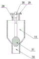
FIG. 5 is a front sectional view of the feed hopper of the present invention;
FIG. 6 is a front sectional view of the lifter plate of the present invention;
in the figure: 1, supporting a plate; 2, screening the box; 3 a first pulverizer; 4 a feed hopper; 5, vibrating a screen; 6, a material receiving disc; 7 a first discharge hole; 8, a second discharge hole; 9 a second crusher; 10 a third pulverizer; 11 a stirring box; 12 servo electric cylinder; 13 a lifting plate; 14 a first transverse plate; 15 a charging hopper; 16 a third discharge port; 17 a first flapper; 18 a second flapper; 19 a fourth discharge port; 20 a fifth discharge hole; 21 a sixth discharge hole and 22 a third movable baffle; 23 servo motor; 24 a stir bar; 25 driving the trough; 26 air cylinders; 27 a movable block; 28 supporting rods; 29 a second transverse plate; 30 a push rod motor; 31 piston.
Detailed Description
The technical solutions in the embodiments of the present invention will be described clearly and completely with reference to the accompanying drawings in the embodiments of the present invention, and it is obvious that the described embodiments are only some embodiments of the present invention, not all embodiments. Based on the embodiments in the present invention, all other embodiments obtained by a person skilled in the art without creative work belong to the protection scope of the present invention.
Referring to fig. 1-4, the present invention provides a technical solution: a combined crushing device for concentrated feed comprises a supporting plate 1, a screening box 2 and a stirring box 11 are arranged at the top of the supporting plate 1, the top of the screening box 2 is provided with a first crusher 3, the top of the first crusher 3 is provided with a feed hopper 4, the screening box 2 is internally provided with a vibrating screen 5 which is movably connected, the inner wall of the screening box 2 is provided with a receiving disc 6 below the vibrating screen 5, the vibrating screen 5 and the material receiving disc 6 are both inclined towards the stirring box 11, a first discharge hole 7 is arranged on the outer wall of the screening box 2 at the lower side of the vibrating screen 5, a second discharge hole 8 is arranged on the outer wall of the screening box 2 at the lower side of the material receiving disc 6, a second crusher 9 is arranged on the outer wall of the screening box 2 below the first discharge hole 7, a third crusher 10 is arranged below the second discharge hole 8 on the outer wall of the screening box 2, and the second crusher 9 and the third crusher 10 are communicated with the stirring box 11;
a first movable baffle 17 matched with the first discharge hole 7 is arranged on the outer wall of the screening box 2, a second movable baffle 18 matched with the second discharge hole 8 is arranged on the outer wall of the screening box 2, the first movable baffle 17 and the second movable baffle 18 are opened after the materials are screened, the first movable baffle 17 is opened after the materials are screened, the materials on the vibrating screen 5 are discharged, the second movable baffle 18 is opened, the materials on the material receiving disc 6 are discharged, and the discharge after the materials are screened is controlled conveniently;
the second pulverizer 9 is connected with the stirring box 11 through a fourth discharge hole 19, the third pulverizer 10 is connected with the stirring box 11 through a fifth discharge hole 20, the materials pulverized by the second pulverizer 9 can be discharged into the stirring box 11 through the fourth discharge hole 19, and the materials pulverized by the third pulverizer 10 can be discharged into the stirring box 11 through the fifth discharge hole 20, so that the materials pulverized by the second pulverizer 9 and the third pulverizer 10 can be discharged into the stirring box 11;
a sixth discharge hole 21 is formed in the bottom of the outer wall of the stirring box 11 on the side away from the second pulverizer 9, a third movable baffle 22 matched with the sixth discharge hole 21 is arranged on the outer wall of the stirring box 11, the third movable baffle 22 is opened after the materials are stirred, and the stirred materials are discharged through the sixth discharge hole 21, so that the materials can be conveniently discharged after being stirred;
a servo motor 23 is arranged in the center of the top of the stirring box 11, a stirring rod 24 is sleeved on an output shaft of the servo motor 23, the stirring rod 24 extends to the bottom of the inner side of the stirring box 11, the servo motor 23 is started, and the servo motor 23 can drive the stirring rod 24 sleeved on the output shaft to rotate and stir, so that materials can be mixed;
the specific implementation mode is as follows: when the material receiving box is used, materials enter the first pulverizer 3 from the feeding hopper 4, the materials can fall on the vibrating screen 5 after being pulverized by the first pulverizer 3, vibration screening can be carried out, screen blockage can be prevented, small particles of the materials passing through the screen of the vibrating screen 5 can fall on the material receiving plate 6, the first movable baffle 17 and the second movable baffle 18 are opened, large particles of the materials which do not pass through the screen of the vibrating screen 5 can enter the second pulverizer 9 through the first discharge hole 7, small particles of the materials falling on the material receiving plate 6 can enter the third pulverizer 10 through the second discharge hole 8, large particles of the materials and small particles of the materials are pulverized differently, the materials pulverized by the second pulverizer 9 enter the stirring box 11 through the fourth discharge hole 19, the materials pulverized by the third pulverizer 10 enter the stirring box 11 through the fifth discharge hole 20, and the pulverized materials can be fully mixed, the even concentrated feed of granule is smashed to swift efficient, reduces the waste of material, improves material utilization ratio.
Referring to fig. 1 and fig. 5-6, the present invention provides a technical solution: a combined crushing device for concentrated feed further comprises a servo electric cylinder 12, wherein the servo electric cylinder 12 is arranged on one side of the top of the supporting plate 1, a lifting plate 13 is arranged on the top of the servo electric cylinder 12, a first transverse plate 14 in movable connection is arranged on the top of the lifting plate 13, a driving groove 25 is arranged on the top of the lifting plate 13, an air cylinder 26 is arranged at the bottom of the inner wall of the driving groove 25, a movable block 27 in fixed connection is arranged at one end of a piston rod of the air cylinder 26, the top of the movable block 27 is fixedly connected with the first transverse plate 14, a feeding hopper 15 is arranged on one side, far away from the lifting plate 13, of the first transverse plate 14, and a third discharging hole 16 is arranged at the bottom;
the top of the charging hopper 15 is symmetrically provided with support rods 28, the top of each support rod 28 is provided with a second transverse plate 29, the center of the top of each second transverse plate 29 is provided with a push rod motor 30, a piston 31 matched with the third discharge hole 16 is movably arranged in the charging hopper 15, an output shaft of the push rod motor 30 penetrates through the second transverse plate 29 and is fixedly connected with the top of the piston 31, the push rod motor 30 is turned on, and the output shaft of the push rod motor 30 can drive the piston 31 to move up and down, so that the opening and closing of the third discharge hole 16 can be controlled conveniently;
the screening box 2 is arranged between the stirring box 11 and the servo electric cylinder 12, so that the feeding process of the feeding hopper 4 by the feeding hopper 15 can be realized, and the damage caused by the stirring box 11 is avoided;
the specific implementation mode is as follows: during the use, with loading hopper 15 full treat crushing material, upward movement servo electric cylinder 12, make loading hopper 15 bottom be located feeder hopper 4 top, start cylinder 26, cylinder 26's piston rod can drive fixed connection's movable block 27 translation, movable block 27 can drive fixed connection's first diaphragm 14 translation, first diaphragm 14 can drive loading hopper 15 translation, stop when loading hopper 15 moves directly over feeder hopper 4, guarantee to treat that crushing material can enter into feeder hopper 4, open push rod motor 30, push rod motor 30's output shaft can drive piston 31 upward movement, open third discharge gate 16, make the material pass through third discharge gate 16 and enter into feeder hopper 4, realize treating the automatic feeding of crushing material, reduce the manpower expenditure, and the work efficiency is improved.
The utility model discloses a theory of operation:
referring to the attached drawings 1-4 of the specification, the utility model can realize the rapid and efficient crushing of concentrated feed with uniform particles by arranging the vibrating screen 5, the receiving disc 6, the first crusher 3, the second crusher 9, the third crusher 10 and the stirring box 11, thereby reducing the waste of materials and improving the utilization rate of the materials;
further, referring to the attached drawings 1 and 5-6 of the specification, the utility model discloses a set up servo electric jar 12, lifter plate 13 and first horizontal pole 14, can realize waiting to smash the automatic feeding of material, reduce manpower expenditure, improve work efficiency.
It is noted that, herein, relational terms such as first and second, and the like may be used solely to distinguish one entity or action from another entity or action without necessarily requiring or implying any actual such relationship or order between such entities or actions. Also, the terms "comprises," "comprising," or any other variation thereof, are intended to cover a non-exclusive inclusion, such that a process, method, article, or apparatus that comprises a list of elements does not include only those elements but may include other elements not expressly listed or inherent to such process, method, article, or apparatus.
Finally, it should be noted that: although the present invention has been described in detail with reference to the foregoing embodiments, it will be apparent to those skilled in the art that modifications may be made to the embodiments described in the foregoing embodiments, or equivalents may be substituted for elements thereof. Any modification, equivalent replacement, or improvement made within the spirit and principle of the present invention should be included in the protection scope of the present invention.
Claims (7)
1. The utility model provides a concentrated feed is with combination reducing mechanism, includes backup pad (1), its characterized in that: the screening box is characterized in that a screening box (2) and a stirring box (11) are arranged at the top of the supporting plate (1), a first pulverizer (3) is arranged at the top of the screening box (2), a feed hopper (4) is arranged at the top of the first pulverizer (3), a vibrating screen (5) movably connected with the screening box (2) is arranged inside the screening box (2), a receiving tray (6) is arranged below the vibrating screen (5) on the inner wall of the screening box (2), the vibrating screen (5) and the receiving tray (6) are inclined towards the stirring box (11), a first discharging port (7) is arranged on the lower side of the vibrating screen (5) on the outer wall of the screening box (2), a second discharging port (8) is arranged on the lower side of the receiving tray (6) on the outer wall of the screening box (2), a second pulverizer (9) is arranged below the first discharging port (7), and a third pulverizer (10) is arranged below the second discharging port (8) on the outer wall of the screening box (2), second rubbing crusher (9) with third rubbing crusher (10) all with agitator tank (11) link up, backup pad (1) top one side is equipped with servo electric cylinder (12), servo electric cylinder (12) top is equipped with lifter plate (13), lifter plate (13) top is equipped with swing joint's first diaphragm (14), lifter plate (13) top is equipped with driving groove (25), driving groove (25) inner wall bottom is equipped with cylinder (26), the piston rod one end of cylinder (26) is equipped with fixed connection's movable block (27), movable block (27) top with first diaphragm (14) fixed connection, first diaphragm (14) outer wall is kept away from lifter plate (13) one side is equipped with loading hopper (15), loading hopper (15) bottom is equipped with third discharge gate (16).
2. The combined crushing device for concentrated feed according to claim 1, characterized in that: screening case (2) outer wall be equipped with first discharge gate (7) assorted adjustable fender (17), screening case (2) outer wall be equipped with second discharge gate (8) assorted second adjustable fender (18).
3. The combined crushing device for concentrated feed according to claim 1, characterized in that: the second pulverizer (9) is connected with the stirring box (11) through a fourth discharge hole (19), and the third pulverizer (10) is connected with the stirring box (11) through a fifth discharge hole (20).
4. The combined crushing device for concentrated feed according to claim 1, characterized in that: keep away from agitator tank (11) outer wall bottom second rubbing crusher (9) one side is equipped with sixth discharge gate (21), agitator tank (11) outer wall be equipped with sixth discharge gate (21) assorted third adjustable fender (22).
5. The combined crushing device for concentrated feed according to claim 1, characterized in that: agitator tank (11) top center is equipped with servo motor (23), the cover is equipped with puddler (24) on servo motor (23) output shaft, puddler (24) extend to agitator tank (11) inboard bottom.
6. The combined crushing device for concentrated feed according to claim 1, characterized in that: the utility model discloses a material loading machine, including loading hopper (15), bracing piece (28) top are equipped with second diaphragm (29), second diaphragm (29) top center is equipped with push rod motor (30), loading hopper (15) inside activity be equipped with third discharge gate (16) assorted piston (31), push rod motor (30) output shaft passes second diaphragm (29) and with piston (31) top fixed connection.
7. The combined crushing device for concentrated feed according to claim 1, characterized in that: the screening box (2) is arranged between the stirring box (11) and the servo electric cylinder (12).
Priority Applications (1)
| Application Number | Priority Date | Filing Date | Title |
|---|---|---|---|
| CN202021777953.6U CN213254972U (en) | 2020-08-24 | 2020-08-24 | Combined crushing device for concentrated feed |
Applications Claiming Priority (1)
| Application Number | Priority Date | Filing Date | Title |
|---|---|---|---|
| CN202021777953.6U CN213254972U (en) | 2020-08-24 | 2020-08-24 | Combined crushing device for concentrated feed |
Publications (1)
| Publication Number | Publication Date |
|---|---|
| CN213254972U true CN213254972U (en) | 2021-05-25 |
Family
ID=75976204
Family Applications (1)
| Application Number | Title | Priority Date | Filing Date |
|---|---|---|---|
| CN202021777953.6U Active CN213254972U (en) | 2020-08-24 | 2020-08-24 | Combined crushing device for concentrated feed |
Country Status (1)
| Country | Link |
|---|---|
| CN (1) | CN213254972U (en) |
Cited By (1)
| Publication number | Priority date | Publication date | Assignee | Title |
|---|---|---|---|---|
| CN114308341A (en) * | 2021-12-28 | 2022-04-12 | 中粮山萃花生制品(威海)有限公司 | High-oleic acid peanut butter production line and technological process thereof |
-
2020
- 2020-08-24 CN CN202021777953.6U patent/CN213254972U/en active Active
Cited By (1)
| Publication number | Priority date | Publication date | Assignee | Title |
|---|---|---|---|---|
| CN114308341A (en) * | 2021-12-28 | 2022-04-12 | 中粮山萃花生制品(威海)有限公司 | High-oleic acid peanut butter production line and technological process thereof |
Similar Documents
| Publication | Publication Date | Title |
|---|---|---|
| CN205966065U (en) | Fertilizer raw materials processing energy saving and consumption reduction rubbing crusher | |
| CN205392225U (en) | Mixed stirring and smashing device of industrial chemicals | |
| CN213792003U (en) | Concrete recovery plant for building | |
| CN112473821A (en) | Universal pulverizer | |
| CN110694755A (en) | Feed mixing and crushing processing system | |
| CN213254972U (en) | Combined crushing device for concentrated feed | |
| CN210496584U (en) | Feed processing reducing mechanism | |
| CN211190515U (en) | Feed additive reducing mechanism | |
| CN113942122B (en) | Production line for producing concrete from construction waste | |
| CN212576384U (en) | Fodder screening plant is used in poultry production | |
| CN112473872A (en) | A dry mud reducing mechanism dewaters for cement manufacture | |
| CN216025318U (en) | Medicinal pulverizer | |
| CN216149870U (en) | Uniform-granularity scrapped magnesia carbon brick recovery device for crushed magnesia carbon bricks | |
| CN215586736U (en) | Grind meticulous powder coating production with synthesizing reducing mechanism | |
| CN206642847U (en) | It is a kind of to be easy to supplementary material to mix and change the disintegrating machine of cutter head | |
| CN215743988U (en) | Hammer mill for pig feed production | |
| CN212468258U (en) | Environment-friendly mechanical device for crushing solid waste | |
| CN214487209U (en) | Feed grinder | |
| CN201313070Y (en) | Device for screening fermented organic material | |
| CN211838249U (en) | Civil engineering construction material crushing mixes integrated device | |
| CN211099394U (en) | Corn germ dregs of rice production is with raw materials environmental protection breaker | |
| CN210357324U (en) | Novel pulverizer | |
| CN218689844U (en) | Reducing mechanism is used in blanc fixe production | |
| CN217249425U (en) | Automatic reinforced breaker of intermittent type nature | |
| CN219943528U (en) | Shrimp crab microorganism fodder sieving mechanism |
Legal Events
| Date | Code | Title | Description |
|---|---|---|---|
| GR01 | Patent grant | ||
| GR01 | Patent grant |