CN113942122B - Production line for producing concrete from construction waste - Google Patents
Production line for producing concrete from construction waste Download PDFInfo
- Publication number
- CN113942122B CN113942122B CN202111224899.1A CN202111224899A CN113942122B CN 113942122 B CN113942122 B CN 113942122B CN 202111224899 A CN202111224899 A CN 202111224899A CN 113942122 B CN113942122 B CN 113942122B
- Authority
- CN
- China
- Prior art keywords
- crushing
- sand
- production line
- construction waste
- vibrating screen
- Prior art date
- Legal status (The legal status is an assumption and is not a legal conclusion. Google has not performed a legal analysis and makes no representation as to the accuracy of the status listed.)
- Active
Links
Images


Classifications
-
- B—PERFORMING OPERATIONS; TRANSPORTING
- B28—WORKING CEMENT, CLAY, OR STONE
- B28C—PREPARING CLAY; PRODUCING MIXTURES CONTAINING CLAY OR CEMENTITIOUS MATERIAL, e.g. PLASTER
- B28C9/00—General arrangement or layout of plant
- B28C9/02—General arrangement or layout of plant for producing mixtures of clay or cement with other materials
-
- B—PERFORMING OPERATIONS; TRANSPORTING
- B02—CRUSHING, PULVERISING, OR DISINTEGRATING; PREPARATORY TREATMENT OF GRAIN FOR MILLING
- B02C—CRUSHING, PULVERISING, OR DISINTEGRATING IN GENERAL; MILLING GRAIN
- B02C1/00—Crushing or disintegrating by reciprocating members
- B02C1/005—Crushing or disintegrating by reciprocating members hydraulically or pneumatically operated
-
- B—PERFORMING OPERATIONS; TRANSPORTING
- B02—CRUSHING, PULVERISING, OR DISINTEGRATING; PREPARATORY TREATMENT OF GRAIN FOR MILLING
- B02C—CRUSHING, PULVERISING, OR DISINTEGRATING IN GENERAL; MILLING GRAIN
- B02C21/00—Disintegrating plant with or without drying of the material
-
- B—PERFORMING OPERATIONS; TRANSPORTING
- B02—CRUSHING, PULVERISING, OR DISINTEGRATING; PREPARATORY TREATMENT OF GRAIN FOR MILLING
- B02C—CRUSHING, PULVERISING, OR DISINTEGRATING IN GENERAL; MILLING GRAIN
- B02C23/00—Auxiliary methods or auxiliary devices or accessories specially adapted for crushing or disintegrating not provided for in preceding groups or not specially adapted to apparatus covered by a single preceding group
- B02C23/08—Separating or sorting of material, associated with crushing or disintegrating
- B02C23/16—Separating or sorting of material, associated with crushing or disintegrating with separator defining termination of crushing or disintegrating zone, e.g. screen denying egress of oversize material
-
- B—PERFORMING OPERATIONS; TRANSPORTING
- B02—CRUSHING, PULVERISING, OR DISINTEGRATING; PREPARATORY TREATMENT OF GRAIN FOR MILLING
- B02C—CRUSHING, PULVERISING, OR DISINTEGRATING IN GENERAL; MILLING GRAIN
- B02C4/00—Crushing or disintegrating by roller mills
- B02C4/02—Crushing or disintegrating by roller mills with two or more rollers
-
- B—PERFORMING OPERATIONS; TRANSPORTING
- B03—SEPARATION OF SOLID MATERIALS USING LIQUIDS OR USING PNEUMATIC TABLES OR JIGS; MAGNETIC OR ELECTROSTATIC SEPARATION OF SOLID MATERIALS FROM SOLID MATERIALS OR FLUIDS; SEPARATION BY HIGH-VOLTAGE ELECTRIC FIELDS
- B03C—MAGNETIC OR ELECTROSTATIC SEPARATION OF SOLID MATERIALS FROM SOLID MATERIALS OR FLUIDS; SEPARATION BY HIGH-VOLTAGE ELECTRIC FIELDS
- B03C1/00—Magnetic separation
- B03C1/02—Magnetic separation acting directly on the substance being separated
- B03C1/16—Magnetic separation acting directly on the substance being separated with material carriers in the form of belts
- B03C1/22—Magnetic separation acting directly on the substance being separated with material carriers in the form of belts with non-movable magnets
-
- B—PERFORMING OPERATIONS; TRANSPORTING
- B03—SEPARATION OF SOLID MATERIALS USING LIQUIDS OR USING PNEUMATIC TABLES OR JIGS; MAGNETIC OR ELECTROSTATIC SEPARATION OF SOLID MATERIALS FROM SOLID MATERIALS OR FLUIDS; SEPARATION BY HIGH-VOLTAGE ELECTRIC FIELDS
- B03C—MAGNETIC OR ELECTROSTATIC SEPARATION OF SOLID MATERIALS FROM SOLID MATERIALS OR FLUIDS; SEPARATION BY HIGH-VOLTAGE ELECTRIC FIELDS
- B03C1/00—Magnetic separation
- B03C1/02—Magnetic separation acting directly on the substance being separated
- B03C1/30—Combinations with other devices, not otherwise provided for
-
- B—PERFORMING OPERATIONS; TRANSPORTING
- B07—SEPARATING SOLIDS FROM SOLIDS; SORTING
- B07B—SEPARATING SOLIDS FROM SOLIDS BY SIEVING, SCREENING, SIFTING OR BY USING GAS CURRENTS; SEPARATING BY OTHER DRY METHODS APPLICABLE TO BULK MATERIAL, e.g. LOOSE ARTICLES FIT TO BE HANDLED LIKE BULK MATERIAL
- B07B9/00—Combinations of apparatus for screening or sifting or for separating solids from solids using gas currents; General arrangement of plant, e.g. flow sheets
-
- B—PERFORMING OPERATIONS; TRANSPORTING
- B28—WORKING CEMENT, CLAY, OR STONE
- B28C—PREPARING CLAY; PRODUCING MIXTURES CONTAINING CLAY OR CEMENTITIOUS MATERIAL, e.g. PLASTER
- B28C5/00—Apparatus or methods for producing mixtures of cement with other substances, e.g. slurries, mortars, porous or fibrous compositions
-
- B—PERFORMING OPERATIONS; TRANSPORTING
- B28—WORKING CEMENT, CLAY, OR STONE
- B28C—PREPARING CLAY; PRODUCING MIXTURES CONTAINING CLAY OR CEMENTITIOUS MATERIAL, e.g. PLASTER
- B28C7/00—Controlling the operation of apparatus for producing mixtures of clay or cement with other substances; Supplying or proportioning the ingredients for mixing clay or cement with other substances; Discharging the mixture
- B28C7/0007—Pretreatment of the ingredients, e.g. by heating, sorting, grading, drying, disintegrating; Preventing generation of dust
-
- B—PERFORMING OPERATIONS; TRANSPORTING
- B28—WORKING CEMENT, CLAY, OR STONE
- B28C—PREPARING CLAY; PRODUCING MIXTURES CONTAINING CLAY OR CEMENTITIOUS MATERIAL, e.g. PLASTER
- B28C7/00—Controlling the operation of apparatus for producing mixtures of clay or cement with other substances; Supplying or proportioning the ingredients for mixing clay or cement with other substances; Discharging the mixture
- B28C7/04—Supplying or proportioning the ingredients
- B28C7/0481—Plant for proportioning, supplying or batching
-
- B—PERFORMING OPERATIONS; TRANSPORTING
- B28—WORKING CEMENT, CLAY, OR STONE
- B28C—PREPARING CLAY; PRODUCING MIXTURES CONTAINING CLAY OR CEMENTITIOUS MATERIAL, e.g. PLASTER
- B28C7/00—Controlling the operation of apparatus for producing mixtures of clay or cement with other substances; Supplying or proportioning the ingredients for mixing clay or cement with other substances; Discharging the mixture
- B28C7/04—Supplying or proportioning the ingredients
- B28C7/06—Supplying the solid ingredients, e.g. by means of endless conveyors or jigging conveyors
-
- C—CHEMISTRY; METALLURGY
- C04—CEMENTS; CONCRETE; ARTIFICIAL STONE; CERAMICS; REFRACTORIES
- C04B—LIME, MAGNESIA; SLAG; CEMENTS; COMPOSITIONS THEREOF, e.g. MORTARS, CONCRETE OR LIKE BUILDING MATERIALS; ARTIFICIAL STONE; CERAMICS; REFRACTORIES; TREATMENT OF NATURAL STONE
- C04B18/00—Use of agglomerated or waste materials or refuse as fillers for mortars, concrete or artificial stone; Treatment of agglomerated or waste materials or refuse, specially adapted to enhance their filling properties in mortars, concrete or artificial stone
- C04B18/04—Waste materials; Refuse
- C04B18/16—Waste materials; Refuse from building or ceramic industry
-
- C—CHEMISTRY; METALLURGY
- C04—CEMENTS; CONCRETE; ARTIFICIAL STONE; CERAMICS; REFRACTORIES
- C04B—LIME, MAGNESIA; SLAG; CEMENTS; COMPOSITIONS THEREOF, e.g. MORTARS, CONCRETE OR LIKE BUILDING MATERIALS; ARTIFICIAL STONE; CERAMICS; REFRACTORIES; TREATMENT OF NATURAL STONE
- C04B20/00—Use of materials as fillers for mortars, concrete or artificial stone according to more than one of groups C04B14/00 - C04B18/00 and characterised by shape or grain distribution; Treatment of materials according to more than one of the groups C04B14/00 - C04B18/00 specially adapted to enhance their filling properties in mortars, concrete or artificial stone; Expanding or defibrillating materials
- C04B20/02—Treatment
- C04B20/026—Comminuting, e.g. by grinding or breaking; Defibrillating fibres other than asbestos
-
- C—CHEMISTRY; METALLURGY
- C04—CEMENTS; CONCRETE; ARTIFICIAL STONE; CERAMICS; REFRACTORIES
- C04B—LIME, MAGNESIA; SLAG; CEMENTS; COMPOSITIONS THEREOF, e.g. MORTARS, CONCRETE OR LIKE BUILDING MATERIALS; ARTIFICIAL STONE; CERAMICS; REFRACTORIES; TREATMENT OF NATURAL STONE
- C04B28/00—Compositions of mortars, concrete or artificial stone, containing inorganic binders or the reaction product of an inorganic and an organic binder, e.g. polycarboxylate cements
-
- Y—GENERAL TAGGING OF NEW TECHNOLOGICAL DEVELOPMENTS; GENERAL TAGGING OF CROSS-SECTIONAL TECHNOLOGIES SPANNING OVER SEVERAL SECTIONS OF THE IPC; TECHNICAL SUBJECTS COVERED BY FORMER USPC CROSS-REFERENCE ART COLLECTIONS [XRACs] AND DIGESTS
- Y02—TECHNOLOGIES OR APPLICATIONS FOR MITIGATION OR ADAPTATION AGAINST CLIMATE CHANGE
- Y02W—CLIMATE CHANGE MITIGATION TECHNOLOGIES RELATED TO WASTEWATER TREATMENT OR WASTE MANAGEMENT
- Y02W30/00—Technologies for solid waste management
- Y02W30/50—Reuse, recycling or recovery technologies
- Y02W30/91—Use of waste materials as fillers for mortars or concrete
Abstract
The invention provides a production line for preparing concrete from construction waste, and belongs to the technical field of machinery. The method solves the problems that the treatment efficiency of the building refuse treatment production line is low and the building refuse can not be treated into directly used concrete. This production line of concrete is made to building rubbish, including the feed bin that sets gradually, the batcher, jaw breaker, the center feed bin, the impact breaker, vibrating screen one, vibrating screen two, the sand making machine, the sand washer, concrete mixing plant, vibrating screen one and vibrating screen two can divide the grit after smashing respectively to select a plurality of not unidimensional grit and export through corresponding output area, the sand washer links to each other with one of them output area, concrete mixing plant includes a plurality of storage bins, conveyer belt and mixer, the measuring scale is all established to the downside of storage bin, the conveyer belt links to each other with the feed inlet of mixer. The production line for producing the concrete from the construction waste has the advantages of being capable of directly producing the concrete from the construction waste, high in production efficiency, safe and environment-friendly.
Description
Technical Field
The invention belongs to the technical field of machinery, and relates to a production line, in particular to a production line for producing concrete from construction waste.
Background
The construction waste is solid waste generated in the process of building new construction, reconstruction, extension or demolition. Construction waste and demolition construction waste can be classified according to the source of the construction waste. Construction waste is, as the name implies, solid waste generated in new, rebuilding or expanding engineering projects, and demolished construction waste is construction waste generated when demolished a building.
Along with the acceleration of the urban process, urban construction and old urban transformation generate a large amount of construction waste, the quantity of the construction waste is over 1/3 of the total quantity of the urban waste, wherein most of the construction waste is not treated and is transported to suburbs or villages by construction units, and is piled up or buried in open air, a large amount of land is consumed, garbage collection and transportation cost and the like, a large amount of land is occupied, the phenomenon of garbage surrounding villages and surrounding cities is formed, urban and rural images are seriously influenced, and huge environmental problems, economic problems and even social problems are caused. The construction waste recycling work is combined with the production of the economic wall materials, and the construction sand is produced by the construction waste, so that a large amount of construction waste which cannot be treated is consumed, the problem of reasonable utilization of resources is solved, the resource utilization efficiency can be effectively improved, the ecology is protected, and the economic development is promoted.
The construction waste treatment technology in the prior art adopts a method of manually sorting construction waste after crushing the construction waste or adopting a chemical treatment agent to add the construction waste to regenerate the construction material, so as to treat the construction waste, but the construction waste treatment efficiency in the prior stage is low and the construction waste can not be treated into directly used concrete.
Disclosure of Invention
The invention aims to solve the problems in the prior art, and provides a production line for preparing concrete from construction waste, which can directly prepare the concrete from the construction waste, and has the advantages of high production efficiency, safety and environmental protection.
The aim of the invention can be achieved by the following technical scheme: the utility model provides a production line of concrete is made to building rubbish, including feed bin, batcher, jaw breaker, center feed bin, impact breaker, shale shaker one, shale shaker two, system sand machine, sand washer, concrete mixing plant that set gradually, its characterized in that, the batcher set up the downside at the feed bin, the discharge gate of feed bin be linked together with the pan feeding mouth of batcher, the batcher have two discharge gates, one of them discharge gate of batcher with the feed inlet of jaw breaker be linked together, the discharge gate of jaw breaker pass through conveyer belt one and link to each other with the center feed bin, the center feed bin pass through conveyer belt two with impact breaker link to each other, impact breaker pass through conveyer belt three with the shale shaker one, the shale shaker two link to each other, the system sand machine pass through conveyer belt five and the sand washer link to each other, the batcher one and with the conveyer belt that can be equipped with and the sand stone and the one is equipped with in the conveyer belt one of the conveyer belt one and the size of the conveyer belt that the measurement of sand stone and the conveyor belt one is equipped with the conveyer belt one and the size of sand washer is equipped with the conveyer belt one and the size of the conveyer belt that the sand stone is equipped with the one and the size of the conveyor belt one is equipped with the conveyor belt one and the size of the conveyor belt one and the size of the conveyor that the conveyor belt and the one and the size of the conveyor.
During operation, building rubbish is led into in the feed bin, building rubbish in the feed bin falls into the feeder, the feeder gives building rubbish to jaw breaker, squeeze the garrulous building rubbish through jaw breaker, and fall into on the conveyer belt, carry to the center feed bin through conveyer belt one, impurity such as iron nail to building rubbish on the conveyer belt one through the iron remover, then the center feed bin carries building rubbish to the impact breaker through conveyer belt two, crush building rubbish again through the impact breaker, then carry vibrating screen one and vibrating screen two again through conveyer belt three, through vibrating screen one and vibrating screen two will smash the grit after the garrulous respectively and divide into a plurality of different sizes and export through corresponding output belt, vibrating screen two carries the grit of part to the sand maker through conveyer belt four, the sand maker makes the grit into the reclaimed sand, and carry to the sand maker through conveyer belt five, filter the reclaimed sand washer and carry to corresponding output to the output belt, the grit of different sizes is carried to the corresponding bin, set for the grit in the size is carried out the setting for the cement storage hopper again through the conveyer belt, and the high environmental protection has the weight is passed through the setting up to the conveyer belt, the setting for the cement storage hopper, the weight is passed through the setting up to the conveyer belt is high.
In the production line for producing concrete from the construction waste, the control valves for controlling the flow of sand are arranged at the lower parts of the storage bin and the metering scale. The control valve controls the storage bin and the metering scale to be opened and closed, so that the weight of the put sand and stone can be controlled, and the sand and stone proportioning control device has the advantages of convenience in controlling sand and stone proportioning and reliability and stability in operation.
In the production line for producing concrete from the construction waste, the other discharge port of the feeder is communicated with an auxiliary conveying belt, the other end of the auxiliary conveying belt is communicated with a soil removing vibrating screen, the soil removing vibrating screen is provided with a slag soil discharge port and a sand and stone discharge port, and a return conveying belt II is arranged between the sand and stone discharge port and the conveying belt I. The dregs and the sand and stones at the other discharge hole of the feeder are conveyed to the soil removing vibrating screen through the auxiliary conveying belt, the dregs are removed through the soil removing vibrating screen, and then the sand and stones are returned to the conveying belt I through the return conveying belt II and are conveyed into the central storage bin for a while through the conveying belt, so that the utilization rate of the construction waste is improved.
In the production line for producing concrete from the construction waste, the iron remover is arranged on the upper side of the second conveying belt, and is a super-magnetic iron remover. The iron remover adopts a super-magnetic iron remover and has the advantage of good iron removal effect.
In the production line for producing concrete from the construction waste, the lower side of the second vibrating screen is connected with the first output belt for conveying 0-5mm reclaimed sand, the second output belt for conveying 5-10 mm broken stone and the third output belt for conveying 10-25 mm reclaimed stone, and the return conveying belt is used for conveying stones exceeding 25 mm. By adopting the arrangement, the sandstone aggregate passing through the vibrating screen is classified into sandstones with different sizes, so that the sandstone aggregate can be directly made into concrete conveniently, and the vibrating screen has the advantage of convenience in use.
In the production line for producing the concrete from the construction waste, dust collectors are arranged on one side of the conveying belt IV and one side of the conveying belt V. One side of the conveying belt IV and one side of the conveying belt V are provided with dust collectors, dust collection is carried out on the production line, and the environmental protection effect is improved.
In the production line for producing the concrete from the construction waste, a sand and stone crushing device is arranged between the impact crusher and the first vibrating screen.
In the production line of concrete is made to above-mentioned building rubbish, grit reducing mechanism include the base and link firmly the support on the base, the upside of base be equipped with feed bin two, the upper end of feed bin be the feed inlet, the lower extreme of feed bin be the discharge gate, feed bin two in violently be equipped with two crushing roller and drive two crushing roller pivoted actuating mechanism one, the base in be equipped with crushing chamber, the upper end in crushing chamber be for with the discharge gate of feed bin two be linked together the feed inlet, crushing intracavity be equipped with crushing section of thick bamboo, the lateral wall of crushing section of thick bamboo be equipped with a plurality of rows of crushing holes, the base on be equipped with the punching press roller of level setting and can drive the reciprocating horizontal migration of punching press roller two, the punching press roller with the crushing hole one-to-one just the punching press roller can stretch into in the crushing hole, the lower extreme in crushing chamber be equipped with, the base on be equipped with can drive a rolling mechanism who rolls pivoted feed inlet that the crushing chamber is equipped with, the crushing chamber can drive a rotary mechanism that the filter just can make crushing roller and the filter can drive in proper order to the discharge gate.
During operation, treat smashing the grit and enter into the feed bin in two through the feed inlet, rotate through two crushing roller and treat smashing the grit and carry out crushing processing once, the grit after the last crushing enters into crushing downthehole through the discharge gate, rotary mechanism drives crushing section of thick bamboo and rotates and make crushing hole and ram roller face to mutually, then driving mechanism two drives the ram roller and removes and make the ram roller remove to the crushing downthehole grit of going on secondary smashing of crushing downthehole grit, then driving mechanism two drives the ram roller and resets and make the ram roller break away from crushing hole, then rotary mechanism drives crushing section of thick bamboo and rotates and make crushing hole vertical down, the grit after smashing falls into the filter on and filters and discharge, simple structure is compact, smash the grit effectual and the advantage that work efficiency is high.
In the production line for producing the concrete from the construction waste, the first driving mechanism is a first gear motor with a shell fixedly connected to the base, and a rotating shaft of the first gear motor is fixedly connected with the crushing roller. The first driving mechanism adopts the first gear motor and has the advantages of simple structure and reliable and stable operation.
In the production line for producing concrete from the construction waste, the second driving mechanism comprises a rotating frame with one end hinged to the base, connecting rods are hinged to two sides of the lower end of the rotating frame, mounting rods are hinged to the outer ends of the two connecting rods, the stamping roller is fixedly connected to the mounting rods, a stamping cylinder is arranged on the support, a cylinder body of the stamping cylinder is hinged to the base, and a piston rod of the stamping cylinder is hinged to the middle of the rotating frame. The punching press cylinder drives the swivel mount swing and drives the punching press roller reciprocating motion, makes the punching press roller can stretch into crushing hole and smash the grit, has crushing effectual and simple structure, easy dismounting's advantage.
In the production line for producing the concrete from the construction waste, a fish-eye joint is arranged between the rotating frame and the connecting rod, and two ends of the fish-eye joint are fixedly connected with the rotating frame and the connecting rod respectively. The fish eye joint is arranged between the rotating frame and the connecting rod, so that the device has the advantages of reliable work and convenient installation.
In the production line for producing the concrete from the construction waste, a row of guide holes are horizontally formed in the side portion of the base, the guide holes correspond to the stamping rollers one by one, the inner ends of the guide holes are communicated with the crushing cavity, and the stamping rollers penetrate through the guide holes. The stamping roller passes through the guide hole, has better guide effect on the movement of the stamping roller, and improves the working reliability.
In the production line for producing the concrete from the construction waste, the rotating mechanism comprises a rotating cylinder with a cylinder body hinged on the bracket, a swinging rod is arranged between a piston rod of the rotating cylinder and the outer end of the crushing cylinder, and two ends of the swinging rod are respectively fixedly connected with the piston rod of the rotating cylinder and the outer end of the crushing cylinder.
In the production line for producing the concrete from the construction waste, two crushing cylinders, two groups of stamping rollers, a second driving mechanism and a rotating mechanism are arranged in the crushing cavity, and the two groups of stamping rollers, the second driving mechanism and the rotating mechanism are arranged in a bilateral symmetry mode.
In the production line for producing the concrete from the construction waste, the lower end of the base is provided with the sliding groove which is horizontally arranged, and the sliding groove is internally provided with the filter plate. The filter inserts in the spout, is convenient for screen the grit after crushing, has simple structure and the better advantage of screening effect.
In the production line for producing concrete from the construction waste, two rows of pulleys are axially and fixedly connected to two sides of the chute, two side edges of the filter plate are embedded in the chute, and lower end faces of two sides of the filter plate are abutted against the pulleys. The two side edges of the filter plate are inserted into the sliding groove along the pulleys, so that the filter plate has the advantages of convenience in disassembly and assembly and labor saving.
In the production line for producing concrete from the construction waste, the impact crusher comprises a hollow frame, a shell is arranged on the frame, the shell comprises a feeding end and a crushing cavity, the lower end of the frame is a discharging end, a rotor is arranged in the crushing cavity in a penetrating mode, a motor is arranged on the frame and drives the rotor to rotate, a plurality of plate hammers are arranged on the outer side wall of the rotor in a surrounding mode, a first impact plate and a second impact plate are arranged in the crushing cavity, one end of the first impact plate is hinged to the shell, a driving mechanism III is arranged between the other end of the first impact plate and the shell, and the driving mechanism III can drive the first impact plate to swing back and forth relative to the rotor. During operation, building rubbish enters into crushing intracavity through the feed end, drives the rotor through the motor and rotates, and the rotor drives the board hammer and rotates, carries out crushing processing to building rubbish, and partial material is got rid of and carries out the secondary crushing on first counterattack board and the second counterattack board, drives first counterattack board swing through actuating mechanism three, when carrying out the secondary crushing to the material, can make the breakage more even, has job stabilization reliable, advantage that work efficiency is high simultaneously.
In the production line for producing concrete from the construction waste, the first impact plate comprises a plate body, a plurality of tooth-shaped bodies are inserted and fixedly connected on the plate body, and the plate body is fixedly connected with the tooth-shaped bodies through screws. The toothed body is inserted on the plate body and fixedly connected through the screw, and has the advantages of convenient manufacture and convenient replacement of the toothed body or the plate body.
In the production line for producing the concrete from the construction waste, the driving mechanism III comprises a first oil cylinder, the cylinder body of which is hinged to the shell, and a piston rod of the first oil cylinder is hinged to the other end of the first impact plate. The driving mechanism III adopts the first oil cylinder, and the angle of the first impact plate can be adjusted in the crushing process, so that the crushing effect is improved.
In the production line for producing the concrete from the construction waste, the driving mechanism III comprises a first cylinder, the cylinder body of which is hinged to the shell, and a piston rod of the first cylinder is hinged to the other end of the first impact plate.
In the production line for producing the concrete from the construction waste, a driving mechanism IV is arranged between the second impact plate and the shell, and the driving mechanism IV can drive the second impact plate to reciprocate relative to the rotor. The second impact plate is driven to lift by the driving mechanism IV, so that the clearance between the rotor and the second impact plate is adjusted, and the crushing efficiency is improved.
In the production line for producing the concrete from the construction waste, the driving mechanism IV is an oil cylinder II with a cylinder body fixedly connected to the shell, and a piston rod of the oil cylinder II is fixedly connected with the second impact plate. The driving mechanism IV adopts the oil cylinder II, and has the advantages of large acting force, simple structure and convenient installation.
In the production line for producing concrete from the construction waste, the sections of the first impact plate and the second impact plate are in a zigzag shape. By adopting the arrangement, the device has the advantage of good chopping effect.
In the production line for producing concrete from the construction waste, the rotating shaft of the motor and the outer end of the rotor are in phase transmission through the synchronous belt.
In the production line for producing concrete from the construction waste, the section of the rotor is square, the outer side wall of the rotor is provided with the strip-shaped groove, the inner end of the plate hammer is embedded in the strip-shaped groove, and the plate hammer is fixedly connected with the rotor through the screw. By adopting the arrangement, the positioning effect on the plate hammer is good and the connection is more convenient.
Compared with the prior art, the production line for preparing concrete from the construction waste has the following advantages:
1. crushing building garbage through a jaw crusher and a counterattack crusher, separating out sand and stones with different sizes through a vibrating screen I and a vibrating screen II, conveying the sand and stones with different sizes into corresponding storage bins, conveying the sand and stones to a conveyor belt according to set weight through a metering scale, and conveying the sand and stones to a mixer through the conveyor belt to mix the sand and stones into concrete, so that the method has the advantage of high production efficiency;
2. the dregs and sand at the other discharge port of the feeder are conveyed to the soil removing vibrating screen through the auxiliary conveying belt, the dregs are removed through the soil removing vibrating screen, and then sand and sand are returned to the conveying belt I through the feed back conveying belt II and conveyed into the central storage bin for a while through the conveying belt, so that the utilization rate of the construction waste is improved;
3. the punching press cylinder drives the swivel mount swing and drives the punching press roller reciprocating motion, makes the punching press roller can stretch into crushing hole and smash the grit, has crushing effectual and simple structure, easy dismounting's advantage.
Drawings
Fig. 1 is a schematic view of an embodiment of a production line for producing concrete from the construction waste.
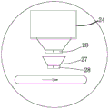
Fig. 2 is a schematic diagram of a storage bin and a stirrer of the production line.
Fig. 3 is a schematic view of a stirrer of the present production line.
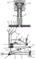
Fig. 4 is a schematic perspective view of the impact crusher of the present production line.
Fig. 5 is a schematic cross-sectional view of the impact crusher of the present line. .
Fig. 6 is a schematic diagram of a second embodiment of the present construction waste concrete production line.
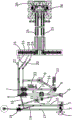
Fig. 7 is a schematic perspective view of a sand crushing apparatus according to a second embodiment of the production line.
FIG. 8 is a schematic top view of a sand crushing apparatus according to a second embodiment of the production line.
FIG. 9 is a schematic cross-sectional view of a sand crushing apparatus according to a second embodiment of the present production line.
Fig. 10 is a schematic diagram of a storage bin, a metering scale and a control valve of the production line.
In the figure, 1, a storage bin; 2. a feeder; 3. jaw crusher; 4. a central stock bin; 5. a counterattack crusher; 5a, a frame; 5b, a shell; 5b1, a feeding end; 5b2, a crushing cavity; 5b3, a discharging end; 5c, a rotor; 5c1, a strip-shaped groove; 5d, a plate hammer; 5e, a motor; 5f, a first impact plate; 5f1, a plate body; 5f2, tooth form; 5g, a second impact plate; 5h, an oil cylinder I; 5i, a screw; 5j, an oil cylinder II; 6. a first vibrating screen; 7. a second vibrating screen; 8. a sand making machine; 9. a sand washer; 10. a first conveyer belt; 11. a second conveyer belt; 12. a third conveyer belt; 13. a conveying belt IV; 14. a conveyer belt V; 15. an iron remover; 16. a first feed back conveyer belt; 17. an auxiliary conveyor belt; 18. a soil removing vibrating screen; 19. a second feed back conveyer belt; 20. an output belt I; 21. an output belt II; 22. an output belt III; 23. a dust remover; 24. a storage bin; 25. a conveyor belt; 26. a stirrer; 27. a metering scale; 28. a control valve; 29. a sand and stone crushing device; 29a, a base; 29a1, crushing chamber; 29a2, guide holes; 29a3, a bracket; 29b, a second bin; 29b1, a feed inlet; 29c, crushing roller; 29d, a first driving mechanism; 29d1, first gear motor; 29e, crushing cylinder; 29e1, crushing the hole; 29f, stamping rollers; 29g, a second driving mechanism; 29g1, a rotating rack; 29g2, connecting rod; 29g3, mounting bar; 29g4, fish eye linker; 29g5, punching cylinder; 29h, a filter plate; 29i, a rotating mechanism; 29i1, a rotary cylinder; 29i2, a swing rod; 29j, a chute; 29k, pulleys.
Detailed Description
The following are specific embodiments of the present invention and the technical solutions of the present invention will be further described with reference to the accompanying drawings, but the present invention is not limited to these embodiments.
Example 1
As shown in figures 1 to 5 and 10, the production line for producing concrete from construction waste comprises a feed bin 1, a feeder 2, a jaw crusher 3, a central feed bin 4, a reaction crusher 5, a first vibrating screen 6, a second vibrating screen 7, a sand making machine 8, a sand washer 9 and a concrete mixing station which are sequentially arranged, wherein the feeder 2 is arranged at the lower side of the feed bin 1, a discharge port of the feed bin 1 is communicated with a feed port of the feeder 2, the feeder 2 is provided with two discharge ports, one of the discharge ports of the feeder 2 is communicated with a feed port of the jaw crusher 3, the discharge port of the jaw crusher 3 is connected with the central feed bin 4 through a first conveying belt 10, the central feed bin 4 is connected with the reaction crusher 5 through a second conveying belt 11, the reaction crusher 5 is connected with the first vibrating screen 6 and the second vibrating screen 7 through a third conveying belt 12, the second vibrating screen 7 is connected with the sand making machine 8 through the fourth conveying belt 13, the sand making machine 8 is connected with the sand washer 9 through the fifth conveying belt 14, the first vibrating screen 6 and the second vibrating screen 7 can respectively separate crushed sand from recycled sand with the size of 0-5mm, crushed stone with the size of 5-10 mm, recycled stone with the size of 10-25 mm and stone with the size of more than 25mm, the first vibrating screen 6 and the second vibrating screen 7 are connected with the first output belt 20 for conveying the recycled sand with the size of 0-5mm, the second output belt 21 for conveying the crushed stone with the size of 5-10 mm and the third output belt 22 for conveying the recycled stone with the size of 10-25 mm, the first return conveying belt 16 is arranged between the first vibrating screen 6 and the first conveying belt 10, and the first return conveying belt 16 returns the stone with the size of more than 25mm to the first conveying belt 10.
The sand washer 9 links to each other with one of them output area, and concrete batching plant includes a plurality of storage silo 24, conveyer belt 25 and mixer 26, and storage silo 24 is located the terminal one side of conveyer belt, and the downside of storage silo 24 all is equipped with one-to-one's measurement and calls 27, and the lower part of storage silo 24 and measurement and calls 27 all is equipped with the control valve 28 that is used for controlling the grit flow, and measurement and calls 27 are located the upside of conveyer belt 25 and conveyer belt 25 links to each other with the feed inlet of mixer 26.
The other discharge gate intercommunication of batcher 2 has auxiliary conveyor 17, and auxiliary conveyor 17's the other end intercommunication has removes native shale shaker 18, removes native shale shaker 18 and has dregs discharge gate and grit discharge gate, is equipped with feed back conveyer belt two 19 between grit discharge gate and the conveyer belt one 10, removes dregs through removing native shale shaker 18, then returns the grit to conveyer belt one 10 through feed back conveyer belt two 19 to in can delivering to center feed bin 4 through conveyer belt one 10, improved the utilization ratio of construction waste.
The impact crusher 5 comprises a hollow frame 5a, a shell 5b is arranged on the frame 5a, the shell 5b comprises a feeding end 5b1 and a crushing cavity 5b2, the lower end of the frame 5a is a discharging end 5b3, a rotor 5c is arranged in the crushing cavity 5b2 in a penetrating mode, a motor 5e is arranged on the frame 5a, and a rotating shaft of the motor 5e and the outer end of the rotor 5c are in transmission through a synchronous belt. The outer side wall ring of rotor 5c is equipped with a plurality of board hammers 5d, be equipped with first counterattack board 5f and second counterattack board 5g in the crushing chamber 5b2, the cross-section of first counterattack board 5f and second counterattack board 5g is the zigzag first counterattack board 5 f's one end articulates on casing 5b, be equipped with driving mechanism three between the other end of first counterattack board 5f and the casing 5b and driving mechanism three can drive the reciprocal swing of relative rotor 5c of first counterattack board 5f, first counterattack board 5f includes plate body 5f1, insert on the plate body 5f1 and link firmly a plurality of tooth-shaped body 5f2, and link firmly through screw 5i between plate body 5f1 and the tooth-shaped body 5f 2.
The driving mechanism III comprises a first oil cylinder 5h with a cylinder body hinged on the shell 5b, a piston rod of the first oil cylinder 5h is hinged with the other end of the first impact plate 5f, and the angle of the first impact plate 5f is adjusted through the first oil cylinder 5h in the crushing process, so that the crushing effect is improved. Alternatively, the driving mechanism III includes a first cylinder having a cylinder body hinged to the housing 5b, and a piston rod of the first cylinder is hinged to the other end of the first striking plate 5 f.
A driving mechanism four is arranged between the second impact plate 5g and the shell 5b, the driving mechanism four can drive the second impact plate 5g to reciprocate relative to the rotor 5c, the driving mechanism four is an oil cylinder two 5j fixedly connected to the shell 5b through a cylinder body, a piston rod of the oil cylinder two 5j is fixedly connected with the second impact plate 5g, and the oil cylinder two 5j drives the second impact plate 5g to reciprocate, so that the gap between the rotor 5c and the second impact plate 5g is adjusted, the crushing efficiency is improved, and the device has the advantages of large acting force, simple structure and convenience in installation.
The cross section of rotor 5c is square, and rotor 5 c's lateral wall all is equipped with bar recess 5c1, and board hammer 5 d's inner inlays in bar recess 5c1, and board hammer 5d links firmly with rotor 5c through screw 5i mutually, to the effectual and comparatively convenient advantage of connection of location of board hammer 5 d.
The upper side of the second conveyer belt 11 is provided with an iron remover 15, and the iron remover 15 is a super-magnetic iron remover 15 and has the advantage of good iron removal effect. One side of the conveyer belt IV 13 and one side of the conveyer belt V14 are provided with dust collectors 23, dust collection is carried out on the production line, and the environmental protection effect is improved.
During operation of the impact crusher 5, building rubbish is led into the bin 1, the building rubbish in the bin 1 falls into the feeder 2, the feeder 2 gives the building rubbish to the jaw crusher 3, the building rubbish is crushed through the jaw crusher 3 and falls onto the first conveyor belt 10, the building rubbish is conveyed to the central bin 4 through the first conveyor belt 10, the iron nails and other impurities of the building rubbish on the first conveyor belt 10 are conveyed to the second conveyor belt 11 through the iron remover 15, the central bin 4 conveys the building rubbish to the impact crusher 5, the building rubbish is crushed again through the impact crusher 5, and the building rubbish is conveyed to the first vibrating screen 6 and the second vibrating screen 7 through the third conveyor belt 12. When the impact crusher 5 crushes the construction waste, the construction waste enters the crushing cavity 5b2 through the feeding end 5b1, the rotor 5c is driven to rotate by the motor 5e, the rotor 5c drives the plate hammer 5d to rotate, the construction waste is crushed, and part of materials are thrown to the first impact plate 5f and the second impact plate 5g for secondary crushing.
The first vibrating screen 6 and the second vibrating screen 7 can respectively separate crushed sand into 0-5mm of reclaimed sand, 5-10 mm of crushed stone, 10-25 mm of reclaimed stone and more than 25mm of stone, and output the sand through the first output belt 20, the second output belt 21 and the third output belt 22, a first return conveying belt 16 is arranged between the first vibrating screen 6 and the first conveying belt 10, and the first return conveying belt 16 returns the stones more than 25mm to the first conveying belt 10. The vibrating screen II 7 conveys part of sand and stone to the sand making machine 8 through the conveying belt IV 13, the sand making machine 8 makes sand and stone into reclaimed sand, the reclaimed sand is conveyed to the sand washer 9 through the conveying belt V14, the reclaimed sand is filtered, washed and conveyed to the corresponding output belt to be output through the sand washer 9, the corresponding sand and stone are conveyed to the corresponding storage bin 24 through the output belt I20, the output belt II 21 and the output belt III 22, and the cement additive is added into the other storage bin 24. The control valve 28 controls the opening and closing of the storage bin 24 and the metering scale 27, sand, stone and cement in the storage bin 24 are conveyed to the conveying belt 25 according to set weight, and are conveyed to the mixer 26 through the conveying belt 25 to be mixed into concrete. The downside of mixer 26 is equipped with the parking stall that is used for parking the concrete carrier, is equipped with the spraying mechanism that can spray the concrete carrier on the parking stall, when loading into the concrete to the carrier, is convenient for wash the concrete carrier.
Example two
The present embodiment is substantially the same in structure and principle as the first embodiment, except that: as shown in fig. 6 to 9, a sand and gravel crushing device 29 is arranged between the impact crusher 5 and the first vibrating screen 6, the sand and gravel crushing device 29 comprises a base 29a and a support 29a3 fixedly connected to the base 29a, a second storage bin 29b is arranged on the upper side of the base 29a, a feed inlet 29b1 is arranged at the upper end of the second storage bin 29b, a discharge outlet is arranged at the lower end of the second storage bin 29b, two crushing rollers 29c and a first driving mechanism 29d for driving the two crushing rollers 29c to rotate are transversely arranged in the second storage bin 29b, engagement teeth are uniformly distributed on the outer side wall of the crushing roller 29c, the first driving mechanism 29d is a first gear motor 29d1 with a shell fixedly connected to the base 29a, and the rotating shaft of the first gear motor 29d1 is fixedly connected with the crushing roller 29 c.
The base 29a is internally provided with a crushing cavity 29a1, the upper end of the crushing cavity 29a1 is provided with a feed inlet 29b1 communicated with a discharge hole of a second storage bin 29b, the crushing cavity 29a1 is internally provided with a crushing barrel 29e, the outer side wall of the crushing barrel 29e is provided with a plurality of rows of crushing holes 29e1, the base 29a is provided with a horizontally arranged press roller 29f and a second driving mechanism 29g capable of driving the press roller 29f to reciprocate horizontally, the second driving mechanism 29g comprises a rotating frame 29g1, one end of the rotating frame 29g1 is hinged to the base 29a, two sides of the lower end of the rotating frame 29g1 are hinged to a connecting rod 29g2, a fish eye joint 29g4 is arranged between the rotating frame 29g1 and the connecting rod 29g2, and two ends of the fish eye joint 29g4 are respectively fixedly connected with the rotating frame 29g1 and the connecting rod 29g 2. The outer ends of the two connecting rods 29g2 are hinged with a mounting rod 29g3, a stamping roller 29f is fixedly connected to the mounting rod 29g3, a stamping cylinder 29g5 is arranged on the support 29a3, a cylinder body of the stamping cylinder 29g5 is hinged on the base 29a, a piston rod of the stamping cylinder 29g5 is hinged with the middle part of the rotating frame 29g1, and as another mode, the stamping cylinder 29g5 is replaced by an oil cylinder.
The punching rollers 29f and the crushing holes 29e1 are in one-to-one correspondence, the punching rollers 29f can extend into the crushing holes 29e1, the lower end of the crushing cavity 29a1 is provided with a filter plate 29h, the base 29a is provided with a rotating mechanism 29i capable of driving the crushing barrel 29e to rotate, and the rotating mechanism 29i can drive the crushing barrel 29e to rotate so that the crushing holes 29e1 can be opposite to the discharge hole of the second bin 29b, the punching rollers 29f and the filter plate 29h in sequence.
The lateral part level of base 29a is equipped with a row of guiding hole 29a2, and guiding hole 29a2 and stamping roller 29f one-to-one correspond, and the inner and crushing chamber 29a1 of guiding hole 29a2 are linked together, and stamping roller 29f passes guiding hole 29a2, has better guiding action to stamping roller 29 f's removal, has improved the reliability of work.
The rotating mechanism 29i comprises a rotating cylinder 29i1 with a cylinder body hinged on a bracket 29a3, a swing rod 29i2 is arranged between a piston rod of the rotating cylinder 29i1 and the outer end of the crushing cylinder 29e, and two ends of the swing rod 29i2 are respectively fixedly connected with the piston rod of the rotating cylinder 29i1 and the outer end of the crushing cylinder 29 e.
Two crushing cylinders 29e, two sets of press rollers 29f, a second driving mechanism 29g and a rotating mechanism 29i are arranged in the crushing cavity 29a1, and the two sets of press rollers 29f, the second driving mechanism 29g and the rotating mechanism 29i are symmetrically arranged on the left and right.
The lower extreme of base 29a is equipped with the spout 29j that the level set up, and spout 29j interpolation is equipped with filter 29h, and the both sides axial of spout 29j has linked firmly two rows of pulleys 29k, and the both sides edge of filter 29h inlays in spout 29j and the lower terminal surface of the both sides of filter 29h supports and leans on pulley 29k, has easy dismounting laborsaving advantage.
During operation, sand to be crushed enters the second bin 29b through the feed port 29b1, the first reducing motor 29d1 drives the two crushing rollers 29c to rotate to crush sand to be crushed once, sand after the primary crushing enters the crushing hole 29e1 through the discharge port, the rotary cylinder 29i1 drives the crushing cylinder 29e to rotate through the swing rod 29i2 so that the crushing hole 29e1 is opposite to the punching roller 29f, the punching cylinder 29g5 drives the rotary frame 29g1 to swing, the rotary frame 29g1 drives the connecting rod 29g2 and the mounting rod 29g3 to move, thereby driving the punching roller 29f to move into the crushing hole 29e1 to crush sand in the crushing hole 29e1 for the second time, the punching cylinder 29g5 drives the punching roller 29f to reset so that the punching roller 29f is separated from the crushing hole 29e1, the rotary cylinder 29i1 drives the crushing cylinder 29e to rotate through the swing rod 29i2 so that the crushing hole 29e1 is vertical downwards, and crushed sand falls into the filter plate 29h to be filtered and discharged. The punching cylinder 29g5 drives the rotating frame 29g1 to swing and drives the punching roller 29f to reciprocate, so that the punching roller 29f can extend into the crushing hole 29e1 to crush sand and stone, and the sand crushing device has the advantages of good crushing effect, simple structure and convenience in disassembly and assembly. The filter 29h inserts in spout 29j, is convenient for carry out the screening to the grit after the crushing, has simple structure and the better advantage of screening effect.
The specific embodiments described herein are offered by way of example only to illustrate the spirit of the invention. Those skilled in the art may make various modifications or additions to the described embodiments or substitutions thereof without departing from the spirit of the invention or exceeding the scope of the invention as defined in the accompanying claims.
The concrete structures of the feeder 2, the jaw crusher 3, the central stock bin 4 and the soil removal vibrating screen 18 refer to a solid waste tailing and construction waste comprehensive utilization production workshop (publication number: CN 109013015A); the concrete structure of the sand making machine 8 and the sand washing machine 9 refers to a sand and stone production line with the sand washing machine (application number 201711430270.6); concrete mixing plant specific structure reference is made to a concrete mixing plant (application number 201811051054.5).
Although the terms of the bin 1, feeder 2, jaw crusher 3, central bin 4, impact crusher 5, frame 5a, housing 5b, feed end 5b1, crushing chamber 5b2, discharge end 5b3, rotor 5c are used more herein, the possibility of using other terms is not excluded. These terms are used merely for convenience in describing and explaining the nature of the invention; they are to be interpreted as any additional limitation that is not inconsistent with the spirit of the present invention.
Claims (10)
1. The production line for producing concrete from construction waste comprises a bin (1), a feeder (2), a jaw crusher (3), a central bin (4), a reaction crusher (5), a first vibrating screen (6), a second vibrating screen (7), a sand making machine (8), a sand washer (9) and a concrete mixing station which are sequentially arranged, and is characterized in that the feeder (2) is arranged at the lower side of the bin (1), the discharge port of the bin (1) is communicated with the feed port of the feeder (2), the feeder (2) is provided with two discharge ports, one discharge port of the feeder (2) is communicated with the feed port (29 b 1) of the jaw crusher (3), the discharge port of the jaw crusher (3) is connected with the central bin (4) through a first conveying belt (10), the central bin (4) is connected with the reaction crusher (5) through a second conveying belt (11), the reaction crusher (5) is provided with a third conveying belt (12), one discharge port of the jaw crusher (2) is connected with the sand washer (8) through a second conveying belt (7) through a second vibrating screen (14), the vibrating screen I (6) and the vibrating screen II (7) can respectively separate crushed sand and stone with different sizes and output the crushed sand through corresponding output belts, the sand washer (9) is connected with one output belt, a return conveying belt I (16) is arranged between the vibrating screen I (6) and the conveying belt I (10), the return conveying belt I (16) returns sand exceeding a set size to the conveying belt I (10), the concrete stirring station comprises a plurality of storage bins (24), a conveying belt (25) and a stirrer (26), the storage bins (24) are positioned on one side of the tail end of the conveying belt, metering scales (27) are respectively arranged on the lower sides of the storage bins (24), control valves (28) for controlling flow are respectively arranged on the lower parts of the metering scales (24) and the conveying belts I (10), the metering scales (27) are positioned on the conveying belt (25) and are fixedly connected with a crushing base (29 a) of the sand crusher (29 a) through a stirring device (29 a) which is fixedly connected with the sand and stone crusher (3, the upper side of base (29 a) be equipped with feed bin two (29 b), the upper end of feed bin two (29 b) be feed inlet (29 b 1), the lower extreme of feed bin two (29 b) be the discharge gate, feed bin two (29 b) in transversely be equipped with two crushing roller (29 c) and drive two crushing roller (29 c) pivoted actuating mechanism one (29 d), base (29 a) in be equipped with crushing chamber (29 a 1), the upper end of crushing chamber (29 a 1) be feed inlet (29 b 1) that are linked together with the discharge gate of feed bin two (29 b), crushing chamber (29 a 1) in be equipped with crushing section of thick bamboo (29 e), the lateral wall of crushing section of thick bamboo (29 e) be equipped with a plurality of rows of crushing holes (29 e 1), base (29 a) on be equipped with the compression roller (29 f) of level setting and can drive the reciprocating horizontal drive mechanism two (29 g) of compression roller (29 f), compression roller (29 f) and compression roller (29 f) in can stretch into in the crushing hole one by one.
2. The production line for producing concrete from construction waste according to claim 1, wherein the other discharge port of the feeder (2) is communicated with an auxiliary conveying belt (17), the other end of the auxiliary conveying belt (17) is communicated with a soil removing vibrating screen (18), the soil removing vibrating screen (18) is provided with a residue soil discharge port and a sand and stone discharge port, and a return conveying belt II (19) is arranged between the sand and stone discharge port and the conveying belt I (10).
3. The production line for producing concrete from construction waste according to claim 1, wherein the upper side of the second conveyor belt (11) is provided with an iron remover (15), the iron remover (15) is a super-magnetic iron remover (15), and one side of the fourth conveyor belt (13) and one side of the fifth conveyor belt (14) are provided with dust collectors (23).
4. A production line for producing concrete from construction waste according to claim 1, 2 or 3, characterized in that the first vibrating screen (6) and the second vibrating screen (7) are connected at the lower side with a first output belt (20) for conveying 0-5mm reclaimed sand, a second output belt (21) for conveying 5-10 mm crushed stone and a third output belt (22) for conveying 10-25 mm reclaimed stone, and the first return conveyor belt (16) is used for conveying stones exceeding 25 mm.
5. The production line for producing concrete from construction waste according to claim 1, wherein a filter plate (29 h) is arranged at the lower end of the crushing cavity (29 a 1), a rotating mechanism (29 i) capable of driving the crushing cylinder (29 e) to rotate is arranged on the base (29 a), and the rotating mechanism (29 i) can drive the crushing cylinder (29 e) to rotate so that the crushing hole (29 e 1) can be opposite to the discharge hole of the second storage bin (29 b), the stamping roller (29 f) and the filter plate (29 h) in sequence.
6. The production line for producing concrete from construction waste according to claim 5, wherein the first driving mechanism (29 d) is a first gear motor (29 d 1) fixedly connected to the base (29 a), and a rotating shaft of the first gear motor (29 d 1) is fixedly connected to the crushing roller (29 c).
7. The production line for producing concrete from construction waste according to claim 5, wherein the second driving mechanism (29 g) comprises a rotating frame (29 g 1) with one end hinged to the base (29 a), connecting rods (29 g 2) are hinged to two sides of the lower end of the rotating frame (29 g 1), mounting rods (29 g 3) are hinged to the outer ends of the two connecting rods (29 g 2), the stamping roller (29 f) is fixedly connected to the mounting rods (29 g 3), stamping cylinders (29 g 5) are arranged on the support (29 a 3), a cylinder body of each stamping cylinder (29 g 5) is hinged to the base (29 a), a piston rod of each stamping cylinder (29 g 5) is hinged to the middle of each rotating frame (29 g 1), fish eye joints (29 g 4) are arranged between the rotating frame (29 g 1) and the connecting rods (29 g 2), and two ends of each fish eye joint (29 g 4) are fixedly connected with the corresponding connecting rods (29 g1 and 29g 2).
8. The production line for producing concrete from construction waste according to claim 5, wherein a row of guide holes (29 a 2) are horizontally provided at the side of the base (29 a), the guide holes (29 a 2) are in one-to-one correspondence with the press rollers (29 f), the inner ends of the guide holes (29 a 2) are communicated with the crushing chamber (29 a 1), and the press rollers (29 f) penetrate through the guide holes (29 a 2).
9. The production line for producing concrete from construction waste according to claim 5, 6, 7 or 8, wherein the rotating mechanism (29 i) comprises a rotating cylinder (29 i 1) with a cylinder body hinged on a bracket (29 a 3), a swinging rod (29 i 2) is arranged between a piston rod of the rotating cylinder (29 i 1) and the outer end of the crushing cylinder (29 e), and two ends of the swinging rod (29 i 2) are respectively fixedly connected with the piston rod of the rotating cylinder (29 i 1) and the outer end of the crushing cylinder (29 e).
10. The production line for producing concrete from construction waste according to claim 5, 6, 7 or 8, wherein two crushing cylinders (29 e) and two groups of pressing rollers (29 f), a second driving mechanism (29 g) and a rotating mechanism (29 i) are arranged in the crushing cavity (29 a 1), and the two groups of pressing rollers (29 f), the second driving mechanism (29 g) and the rotating mechanism (29 i) are symmetrically arranged in a left-right direction.
Priority Applications (1)
| Application Number | Priority Date | Filing Date | Title |
|---|---|---|---|
| CN202111224899.1A CN113942122B (en) | 2021-10-21 | 2021-10-21 | Production line for producing concrete from construction waste |
Applications Claiming Priority (1)
| Application Number | Priority Date | Filing Date | Title |
|---|---|---|---|
| CN202111224899.1A CN113942122B (en) | 2021-10-21 | 2021-10-21 | Production line for producing concrete from construction waste |
Publications (2)
| Publication Number | Publication Date |
|---|---|
| CN113942122A CN113942122A (en) | 2022-01-18 |
| CN113942122B true CN113942122B (en) | 2023-04-28 |
Family
ID=79331961
Family Applications (1)
| Application Number | Title | Priority Date | Filing Date |
|---|---|---|---|
| CN202111224899.1A Active CN113942122B (en) | 2021-10-21 | 2021-10-21 | Production line for producing concrete from construction waste |
Country Status (1)
| Country | Link |
|---|---|
| CN (1) | CN113942122B (en) |
Families Citing this family (2)
| Publication number | Priority date | Publication date | Assignee | Title |
|---|---|---|---|---|
| CN115353333B (en) * | 2022-08-19 | 2024-01-05 | 藤县翔兆混凝土有限公司 | Concrete production process |
| CN117103462A (en) * | 2023-10-10 | 2023-11-24 | 廊坊德基机械科技有限公司 | Raw material production system for concrete |
Family Cites Families (12)
| Publication number | Priority date | Publication date | Assignee | Title |
|---|---|---|---|---|
| JP2003126722A (en) * | 2001-10-24 | 2003-05-07 | Mitsubishi Heavy Ind Ltd | Apparatus for crushing resin waste material |
| CN105018114B (en) * | 2015-08-03 | 2017-06-13 | 中冶焦耐工程技术有限公司 | A kind of discharge device roller frame |
| CN206535848U (en) * | 2016-12-30 | 2017-10-03 | 武汉都市环保工程技术股份有限公司 | Building waste processing system |
| CN108187803A (en) * | 2017-12-11 | 2018-06-22 | 王腾蛟 | A kind of sweetened bean paste-making machine tool equipment |
| CN209205515U (en) * | 2018-07-20 | 2019-08-06 | 粤水电建筑安装建设有限公司 | A kind of civil engineering work waste treatment device |
| CN208679251U (en) * | 2018-08-09 | 2019-04-02 | 辽宁工业大学 | A kind of civil engineering work waste treatment device of environmental protection |
| CN209423711U (en) * | 2018-12-27 | 2019-09-24 | 高台县宏源矿业有限责任公司 | A kind of ore crusher |
| CN110052310A (en) * | 2019-05-20 | 2019-07-26 | 枣庄鑫金山智能机械股份有限公司 | A kind of combined vibrating sand making machine |
| CN210410920U (en) * | 2019-08-26 | 2020-04-28 | 聊城大学 | Civil engineering construction waste treatment device |
| CN213161022U (en) * | 2020-07-01 | 2021-05-11 | 淅川县中金制造有限公司 | Old and useless tectorial membrane sand piece breaker |
| CN112892819A (en) * | 2021-01-14 | 2021-06-04 | 中铁四局集团第二工程有限公司 | Construction process for dry-method sand making production of cyclone machine |
| CN113318843A (en) * | 2021-06-10 | 2021-08-31 | 韩保勤 | Crushing device for recycling waste concrete |
-
2021
- 2021-10-21 CN CN202111224899.1A patent/CN113942122B/en active Active
Also Published As
| Publication number | Publication date |
|---|---|
| CN113942122A (en) | 2022-01-18 |
Similar Documents
| Publication | Publication Date | Title |
|---|---|---|
| CN113942122B (en) | Production line for producing concrete from construction waste | |
| CN109092476B (en) | Construction waste treatment equipment | |
| CN209303428U (en) | A kind of building waste recycling equipment | |
| CN111112311B (en) | Building rubbish breaker for building engineering management | |
| CN106702150B (en) | Automatically cleaning pelletizing system of colding pressing | |
| CN202725240U (en) | Double roll crusher for titanium sponge | |
| CN102974596B (en) | Construction waste co-extrusion harmless treatment system and method thereof | |
| CN112108218B (en) | Method for processing cement clinker | |
| CN112123635A (en) | A rubber reducing mechanism for rubber production and processing | |
| CN105498903B (en) | A kind of discarded concrete prepares the system and device and method of reclaimed sand | |
| CN113171824A (en) | Preparation method of modified aluminate cement | |
| CN208960101U (en) | Automatic circulation type construction waste crushing system | |
| CN203076319U (en) | Innocent treatment system for construction waste by united extrusion | |
| CN213966794U (en) | Secondary crushing equipment for waste concrete slag | |
| CN206652568U (en) | A kind of feed screens pulverizer | |
| CN211160153U (en) | Recycling system is selected separately in building rubbish's breakage | |
| CN210411069U (en) | Crushing system for manufacturing sandstone aggregate | |
| CN210613968U (en) | Crushing device for cement clean production | |
| KR101803964B1 (en) | A crushing system with crushing apparatus of aggregating crushing and particle-spectic collection | |
| CN209934814U (en) | Garbage sorting device for building | |
| CN209646600U (en) | Grinding device is used in a kind of production of ceramic tile | |
| CN116571306A (en) | Crushing and screening device for special asphalt raw materials | |
| CN214765773U (en) | Novel construction waste treatment device | |
| CN211678137U (en) | Screening, crushing and recycling device for dry-mixed mortar raw materials | |
| CN110813510B (en) | Construction waste layering breaker |
Legal Events
| Date | Code | Title | Description |
|---|---|---|---|
| PB01 | Publication | ||
| PB01 | Publication | ||
| SE01 | Entry into force of request for substantive examination | ||
| SE01 | Entry into force of request for substantive examination | ||
| GR01 | Patent grant | ||
| GR01 | Patent grant |