CN213247978U - Chair set - Google Patents
Chair set Download PDFInfo
- Publication number
- CN213247978U CN213247978U CN202021272578.XU CN202021272578U CN213247978U CN 213247978 U CN213247978 U CN 213247978U CN 202021272578 U CN202021272578 U CN 202021272578U CN 213247978 U CN213247978 U CN 213247978U
- Authority
- CN
- China
- Prior art keywords
- chair
- connecting rod
- link
- support
- rod mechanism
- Prior art date
- Legal status (The legal status is an assumption and is not a legal conclusion. Google has not performed a legal analysis and makes no representation as to the accuracy of the status listed.)
- Active
Links
Images


Landscapes
- Special Chairs (AREA)
Abstract
The utility model relates to a chair, which comprises a chair seat, a chair back and a back support, wherein the chair back is connected with the back support through a connecting rod mechanism, the connecting rod mechanism is respectively connected with the back support and the chair back through joint rotation, and an elastic part acting on the connecting rod mechanism is arranged at the joint; the connecting rod mechanism has an extension state and a compression state, and in the extension state, the connecting rod mechanism extends forwards under the action of the elastic piece to enable the chair back to be positioned above the position where the chair seat leans forwards; when the chair is in a compressed state, the chair back is positioned above the position where the chair seat leans back under the action of backward force, and the elastic piece deforms to generate reset elasticity. Particularly, the utility model discloses not only the back of the chair can provide the support for the human body when the human body leans on the back, when the human body leans forward, the elastic component drive link means who has among the link mechanism stretches out forward, continues to provide the support for the human body back. Therefore, the burden of the back of the child can be reduced when the child keeps the learning state for a long time, and the human body can not lean forward when the child has a rest.
Description
Technical Field
The utility model relates to the technical field of seats, concretely relates to chair.
Background
In the present society, child education is a social hotspot, and a good learning condition is that each pair of parents first hope to provide children for themselves, so it is necessary to design a child chair suitable for children to sit on, and nowadays, child chairs on the market are designed from the aspects of correcting the sitting posture of children or adjusting the height of the chair, such as the Chinese bulletin: CN2016214572636 is a highly comfortable adjustable chair, in the course of study, proper rest is indispensable, and the human body is not prevented from leaning forward during rest, the back of the chair of the traditional chair can not continue to provide support for the human body after the human body leans forward, if a child chair which can provide support for the human body no matter when studying or resting can be designed, a better study condition can be provided for children, therefore, how to design a novel child chair which can provide support for the back of the child no matter when studying or resting is a problem that needs to be solved urgently by technical personnel in the field.
Disclosure of Invention
In order to solve the problem that the prior child chair can not provide the supporting function for the back of the human body when the human body leans forward, the utility model provides a novel child chair with the back-tracing function.
A chair comprises a chair seat, a chair back and a back support, wherein the chair back is connected with the back support through a connecting rod mechanism, the connecting rod mechanism is respectively connected with the back support and the chair back in a rotating mode through joints, and elastic pieces acting on the connecting rod mechanism are arranged at the joints; the connecting rod mechanism has an extension state and a compression state, and in the extension state, the connecting rod mechanism extends forwards under the action of the elastic piece to enable the chair back to be positioned above the position where the chair seat leans forwards; when the chair is in a compressed state, the chair back is positioned above the position where the chair seat leans back under the action of backward force, and the elastic piece deforms to generate reset elasticity.
The utility model discloses a novel child chair, its back of the chair pass through a link mechanism and back of the body leg joint, particularly, compare in traditional child chair, the utility model discloses under the condition that can satisfy traditional function, still increased a link mechanism who has two kinds of states, not only the back of the chair can provide the support for the human body when the human body leans on the back, when the human body leans forward, the elastic component drive connecting rod device who has among the link mechanism stretches out forward, continues to provide the support for the human body back. Not only can alleviate the burden of a bit back for children when keeping the learning state for a long time like this, the human body is exempted from to lean forward when the rest, the utility model discloses also can continue to provide the support for it.
Preferably, the elastic member is a torsion spring disposed at the joint. The torsional spring with the reset function is used as the elastic part, so that the design requirement can be met, and the torsional spring can be completely hidden in the joint due to the small size, so that the practical function is met, and the purpose of concise appearance is achieved.
Preferably, the link mechanism comprises a first link, and two ends of the first link are respectively and rotatably connected with the chair back and the back support. Under the condition of meeting the functional requirements, the structure is simplified as much as possible, on one hand, the appearance of the structure is simpler, on the other hand, the structure is more beneficial to future maintenance and repair, and the service life of the product is longer.
Preferably, the chair further comprises a second connecting rod and a third connecting rod, wherein one end of the second connecting rod is fixedly connected with the back support, one end of the third connecting rod is fixedly connected with the back of the chair, and two ends of the first connecting rod are respectively rotatably connected with the other end of the second connecting rod and the other end of the third connecting rod. The second connecting rod and the third connecting rod are respectively arranged at two ends of the first connecting rod, a certain distance can be effectively limited between the first connecting rod and the chair back and the back support, so that a connecting rod mechanism can be completely formed, and friction between the first connecting rod and the chair back and the back support in the using process can be avoided.
Preferably, the first connecting rod is arranged in an inclined mode. The inclination sets up the inclination that can cooperate the human body to sit when leaning on, gives the user a better experience of just sitting.
Preferably, the chair further comprises a base, the base is arranged below the chair seat, the lower end of the back support is fixedly connected to the base, and the connecting rod mechanism is rotatably connected with the upper end of the back support. The increase of height is children's a landmark characteristic, and along with the continuous increase of height, the height of its children's chair that is suitable for also needs to change, sets up link mechanism and back of the body support upper end into rotating and is connected, makes it can carry out certain length adjustment to it according to the increase change of children's height, like this the utility model discloses a life then can be higher.
Preferably, the back support is a column, and the seat is also connected to the back support. Set up the back of the body support into a stand, can guarantee to a certain extent the stability of the seat support of connecting on the back of the body support and the back of the chair, in addition, connect the seat support and the back of the chair on a stand, the relation of cooperation seat support and the back of the chair that can be better, for the user take a better just to sit to experience.
Adopted above-mentioned technical scheme the utility model discloses a design departure point, theory and beneficial effect are:
the utility model provides a novel child chair, when a user sits, the back of the human body is pressed backwards, the chair back can provide a supporting function for the human body, the uncomfortable feeling of the back caused by long sitting can be relieved to a certain extent, and meanwhile, due to the pressure, an elastic part inside a joint of a connecting rod mechanism is compressed to generate reset elasticity; when human back to leaning forward, originally apply the pressure on the back of the chair and leave, the elasticity that resets that the elastic component produced when compression state plays the effect, makes link mechanism extend gradually, thereby drive the back of the chair forward motion, the direction that leans forward along with the human body extends promptly, makes the back of the chair towards the direction motion that the human body leaned forward, thereby reaches the effect of chasing back, the back of the chair still can provide the support for it when the human body leans forward, compare in the child chair in the traditional meaning, the utility model discloses there are multiple design possibility in the outward appearance, can design multiple seat outward appearance according to user's hobby, again at present suitable children just sit, improve the structure on simple structure's the child chair, can let the user realize the function of chasing back that the child chair of tradition does not possess, no matter can let the user obtain a better just sitting experience when studying or having a rest like this.
Drawings
Fig. 1 is a schematic perspective view of the overall assembly of the present invention in an embodiment;
fig. 2 is a left side view of the chair back compressed according to an embodiment of the present invention;
fig. 3 is a left side view of the chair back after being compressed according to the embodiment of the present invention;
fig. 4 is an assembly view of the first, second and third connecting rods and the first and second connecting members according to the embodiment of the present invention;
FIG. 5 is an assembly view of the first and second connecting members and the first and second elastic members according to the embodiment of the present invention;
fig. 6 is a first perspective view of an embodiment of the present invention;
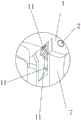
FIG. 7 is an enlarged view of portion a of FIG. 6;
fig. 8 is a second perspective view of the embodiment of the present invention;
FIG. 9 is an enlarged view of portion b of FIG. 8;
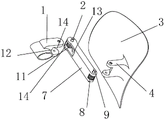
the figures are numbered: a third link 1; a first connecting piece 2; a chair back 3; a second link 4; a seat 5; a back support 6; a first link 7; a second elastic piece 8; a second connecting piece 9; a base 10; a first elastic element 11; the first matching surface 12; a second mating surface 13; a U-shaped groove 14.
Detailed Description
In order to make the aforementioned objects, features and advantages of the present invention more clearly understood, the present invention will be described in further detail with reference to the accompanying drawings and detailed description. It should be noted that the embodiments and features of the embodiments of the present application may be combined with each other without conflict.
In the following description, numerous specific details are set forth in order to provide a thorough understanding of the present invention, however, the present invention may be practiced in other ways than those specifically described herein, and therefore the scope of the present invention is not limited by the specific embodiments disclosed below.
In the description of the present invention, the term "at least one" means one or more unless explicitly defined otherwise. The terms "first," "second," "third," and the like are used for descriptive purposes only and are not to be construed as indicating or implying relative importance.
In the description of the present invention with respect to the direction, the terms "left", "right", "up", "down" refer to: the left view of the utility model is provided with a corresponding left view, a right view, an upper view and a lower view.
The specific implementation manner of the utility model is as follows:
example (b):
as shown in fig. 1-3, the utility model provides a novel child chair, which comprises a chair back 3, a back support 6, a base 10, a chair seat 5 and a link mechanism connecting the chair back 3 and the back support 6, wherein the back support 6 is fixedly connected to the base 10, the chair seat 5 is connected with the lower end of the back support 6, the link mechanism is rotatably connected with the upper end of the back support 6, and the other end of the link mechanism is connected with the chair back;
as shown in fig. 4-8, specifically, the link mechanism is composed of a first link 7, a second link 4, a third link 1, a first connecting part 2 and a second connecting part 9 connecting the links at joints, and a first elastic part 11 and a second elastic part 8 having a restoring function, further, the first elastic part 11 and the second elastic part 8 are torsion springs, and the first elastic part 11 and the second elastic part 8 respectively have two pins, the connecting part is a movable rotating shaft, and the torsion springs are sleeved on the movable rotating shaft; the right end of the third connecting rod 1 is connected with the chair back 3, the left end of the first connecting rod 7 is connected with the lower end of the first connecting rod 7 through a second connecting piece 9, the upper end of the first connecting rod 7 is connected with the right end of the second connecting rod 4 through a first connecting piece 2, and the left end of the second connecting rod 7 is connected with the upper end of the back support 6.
The right end part of the third connecting rod 1 and the left end part of the second connecting rod 4 are respectively provided with a U-shaped groove 14, a first matching surface 12 and a second matching surface 13 which are matched with the upper end and the lower end of the second connecting rod respectively are arranged in the two U-shaped grooves 14, one pin of the first elastic piece 11 is arranged in the first matching surface 12, the other pin is arranged in the second connecting rod 4, one pin of the second elastic piece 8 is arranged in the second matching surface 13, and the other pin is arranged in the second connecting rod 4.
When a human body leans backwards, the link mechanism is gradually compressed, the chair back 3 is located above the position where the chair seat leans backwards under the action of backward force, the first elastic piece 11 and the second elastic piece 8 deform to generate return elastic force, when the human body leans forwards, the pressure originally applied to the chair back 3 disappears, the link mechanism gradually extends, the return elastic force of the first elastic piece 11 and the second elastic piece 8 plays a role, and the link mechanism stretches forwards to enable the chair back 3 to be located above the position where the chair seat 5 leans forwards.
In the embodiment, a user only needs to sit in a mode which is most comfortable by the user per se like a traditional child chair when in use, when in sitting, the user can lean against the back of the user on the chair back 3 to relieve discomfort of the back when sitting for a long time, when the user needs to lean forward the body, the elastic part 11 and the elastic part 8 which have the resetting function in the connecting rod mechanism can drive the chair back to move forward to the direction that the human body leans forward, so that the chair back 3 can provide support for the user no matter the human body leans backward or leans forward, and therefore a more comfortable and more comprehensive sitting experience is achieved.
Claims (7)
1. A chair comprises a chair seat, a chair back and a back support, and is characterized in that the chair back is connected with the back support through a connecting rod mechanism, the connecting rod mechanism is respectively connected with the back support and the chair back in a rotating way through joints, and elastic pieces acting on the connecting rod mechanism are arranged at the joints; the connecting rod mechanism has an extension state and a compression state, and in the extension state, the connecting rod mechanism extends forwards under the action of the elastic piece to enable the chair back to be positioned above the position where the chair seat leans forwards; when the chair is in a compressed state, the chair back is positioned above the position where the chair seat leans back under the action of backward force, and the elastic piece deforms to generate reset elasticity.
2. A chair according to claim 1, wherein the resilient member is a torsion spring disposed at the joint.
3. The chair according to claim 1, wherein the linkage comprises a first link, and both ends of the first link are rotatably connected to the back and the back support, respectively.
4. The chair according to claim 3, further comprising a second link and a third link, wherein one end of the second link is fixedly connected to the back support, one end of the third link is fixedly connected to the back of the chair back, and two ends of the first link are rotatably connected to the other end of the second link and the other end of the third link, respectively.
5. A chair according to claim 4, wherein the first link is inclined.
6. The chair of claim 1, further comprising a base disposed below the seat, wherein the lower end of the back support is fixedly connected to the base, and the linkage is rotatably connected to the upper end of the back support.
7. A chair according to claim 5, wherein the back support is an upright and the seat is also connected to the back support.
Priority Applications (1)
| Application Number | Priority Date | Filing Date | Title |
|---|---|---|---|
| CN202021272578.XU CN213247978U (en) | 2020-07-02 | 2020-07-02 | Chair set |
Applications Claiming Priority (1)
| Application Number | Priority Date | Filing Date | Title |
|---|---|---|---|
| CN202021272578.XU CN213247978U (en) | 2020-07-02 | 2020-07-02 | Chair set |
Publications (1)
| Publication Number | Publication Date |
|---|---|
| CN213247978U true CN213247978U (en) | 2021-05-25 |
Family
ID=75958413
Family Applications (1)
| Application Number | Title | Priority Date | Filing Date |
|---|---|---|---|
| CN202021272578.XU Active CN213247978U (en) | 2020-07-02 | 2020-07-02 | Chair set |
Country Status (1)
| Country | Link |
|---|---|
| CN (1) | CN213247978U (en) |
-
2020
- 2020-07-02 CN CN202021272578.XU patent/CN213247978U/en active Active
Similar Documents
| Publication | Publication Date | Title |
|---|---|---|
| US6722735B2 (en) | Chair with synchronously moving seat and seat back | |
| JPH0146127B2 (en) | ||
| KR102364063B1 (en) | Backrest chair with back-down seat plate structure with forward tilting and left and right rolling functions and a back-pushing structure by a back-down seat plate | |
| CN214631100U (en) | Seat back linkage mechanism | |
| US11910932B2 (en) | Motion chair | |
| JP2006296960A (en) | Chair having massage function | |
| CN110720775A (en) | Inclination and elevation locking control device of dynamic tray | |
| CN110742430A (en) | Dynamic seat | |
| CN213247978U (en) | Chair set | |
| CN210696761U (en) | Comfortable seat | |
| CN211862339U (en) | Waist rest structure of chair | |
| KR102138836B1 (en) | Chair with tilting structure of seat | |
| CN110710815A (en) | Dynamic tray | |
| CN207075770U (en) | A kind of health-care chair | |
| CN211092835U (en) | Elastic support piece and linkage mechanism for seat | |
| CN212521276U (en) | Self-adaptive chair back supporting device | |
| CN210300245U (en) | Rapid and safe deformation chair | |
| CN211092821U (en) | Chair with detachable seat | |
| CN110638241A (en) | Comfortable seat | |
| CN110693222A (en) | Full-dynamic seat-back synchronous linkage device | |
| US20210022508A1 (en) | Horizontal-moving & rocking appliance and rocking chair | |
| CN211092836U (en) | Dynamic tray | |
| CN215650098U (en) | Adjustable seat | |
| CN211092841U (en) | Full-dynamic seat-back synchronous linkage device | |
| CN217987091U (en) | Novel chair |
Legal Events
| Date | Code | Title | Description |
|---|---|---|---|
| GR01 | Patent grant | ||
| GR01 | Patent grant |