CN213239402U - Digital battery anti-falling detection device - Google Patents
Digital battery anti-falling detection device Download PDFInfo
- Publication number
- CN213239402U CN213239402U CN202022538904.3U CN202022538904U CN213239402U CN 213239402 U CN213239402 U CN 213239402U CN 202022538904 U CN202022538904 U CN 202022538904U CN 213239402 U CN213239402 U CN 213239402U
- Authority
- CN
- China
- Prior art keywords
- plate
- digital battery
- detection device
- cylinder
- push rod
- Prior art date
- Legal status (The legal status is an assumption and is not a legal conclusion. Google has not performed a legal analysis and makes no representation as to the accuracy of the status listed.)
- Active
Links
Images


Landscapes
- Testing Or Calibration Of Command Recording Devices (AREA)
Abstract
The utility model discloses a digital battery anti-falling detection device, which belongs to the technical field of digital battery detection, and comprises a box body, a bottom plate is installed in the box body, a support column is installed at the top of the bottom plate, a top plate is installed at the top of the support column, a lead screw is installed between the bottom plate and the top plate in a rotating manner, a lifting plate is sleeved on the support column in a sliding manner, the lifting plate is in threaded connection with the lead screw, a transverse plate is installed on the lifting plate in a sliding manner, a swinging rod is installed at one end of the transverse plate in a rotating manner, a vertically arranged cylinder is fixedly installed on the swinging rod, two arc-shaped rods are hinged to the bottom of the cylinder, a clamping plate; the utility model discloses realize carrying out antidetonation to digital battery and detecting, can carry out the not detection of co-altitude, convenient operation, the electrodynamic operation need not the manual work, the efficiency that very big improvement detected.
Description
Technical Field
The utility model belongs to the technical field of digital battery detects, concretely relates to anti falling detection device of digital battery.
Background
A digital battery: on the basis of a common lead-acid storage battery, a digital chip is installed, so that the battery has functions which are not possessed by the common storage battery. Present digital battery anti-falling detects looks sideways at from the eminence through the manual work, and it is more troublesome to detect like this, inconveniently carries out the not anti-falling of co-altitude and looks sideways at, and detection efficiency is low, and current does not have a section to carry out anti-falling detection's device to digital battery, consequently, needs a digital battery anti-falling detection device to solve above problem.
SUMMERY OF THE UTILITY MODEL
An object of the utility model is to provide an anti detection device that falls of digital battery to solve the problem that proposes among the above-mentioned background art.
In order to achieve the above object, the utility model provides a following technical scheme: a digital battery anti-falling detection device comprises a box body, a bottom plate is installed in the box body, a support column is installed at the top of the bottom plate, a top plate is installed at the top of the support column, a lead screw is installed between the bottom plate and the top plate in a rotating mode, a lifting plate is sleeved on the support column in a sliding mode and in threaded connection with the lead screw, a transverse plate is installed on the lifting plate in a sliding mode, a swinging rod is installed at one end of the transverse plate in a rotating mode, a vertically arranged cylinder is fixedly installed on the swinging rod, the bottom of the cylinder is hinged to two arc-shaped rods, a clamping plate is installed at the bottom of the arc-shaped rods, a movable plate is sleeved on the cylinder in a sliding mode, driving rods are hinged to the two ends of the movable plate, the bottom of each driving rod is hinged, and a rack is slidably arranged at the bottom of the top plate, and the gear is meshed with the rack.
As a preferred embodiment, a bidirectional speed reducing motor is fixedly mounted on the top of the top plate, and an output shaft of the bidirectional speed reducing motor is in transmission connection with the screw rod.
As a preferred embodiment, a sliding groove is formed in the top of the lifting plate, a sliding block is slidably mounted in the sliding groove, the sliding block is fixedly connected with the transverse plate, an electric telescopic rod horizontally arranged is mounted in the sliding groove, and a piston rod of the electric telescopic rod is fixedly connected with the sliding block.
As a preferred embodiment, the top of cylinder is seted up flutedly, the push rod motor is installed in the recess, the push rod fixedly connected with horizontal pole of push rod motor, the both ends bottom fixedly connected with montant of horizontal pole, the bottom and the fly leaf fixed connection of montant, the montant runs through the swinging arms, montant and swinging arms sliding connection.
As a preferred embodiment, a vertically arranged rotating shaft is rotatably mounted at one end of the transverse plate, the oscillating rod is fixedly mounted on the rotating shaft, a servo motor is mounted at the bottom of the transverse plate, and an output shaft of the servo motor is in transmission connection with the rotating shaft.
As a preferred embodiment, a cylinder is fixedly mounted at the bottom of the top plate, and a piston rod of the cylinder is fixedly connected with one side of the rack far away from the gear.
Compared with the prior art, the beneficial effects of the utility model are that:
carry out elevating movement through the fly leaf, the fly leaf drives the actuating lever motion and makes two arc poles reciprocal pendulums, realizes drawing close or separating each other of two grip blocks, draws close through two grip blocks and can grasp digital battery, rotates through the lead screw and makes the lifter plate carry out elevating movement, can carry out not co-altitude's detection, convenient operation.
Carry out horizontal migration through the diaphragm, swing through the swinging arms, adjust the direction of swinging arms, the horizontal migration of cooperation diaphragm realizes carrying out the clamp of different positions to the battery that falls on the bottom plate and gets, carries out a lot of tests, need not the manual work, the efficiency that very big improvement detected.
The utility model discloses realize carrying out antidetonation to digital battery and detecting, can carry out the not detection of co-altitude, convenient operation, the electrodynamic operation need not the manual work, the efficiency that very big improvement detected.
Drawings
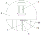
Fig. 1 is a schematic structural view of the present invention;
FIG. 2 is a schematic view of the column mounting structure of the present invention;
FIG. 3 is a schematic view of the structure at A in FIG. 1;
fig. 4 is a schematic view of the sectional structure of the lifting plate of the present invention.
In the figure: 1. a box body; 2. a base plate; 3. a support pillar; 4. a top plate; 5. a screw rod; 6. a lifting plate; 7. a transverse plate; 8. a swing lever; 9. a servo motor; 10. a cylinder; 11. an arcuate bar; 12. a clamping plate; 13. a movable plate; 14. a drive rod; 15. a push rod motor; 16. a bidirectional reduction motor; 17. a gear; 18. a cylinder; 19. a rack; 20. an electric telescopic rod.
Detailed Description
The present invention will be further described with reference to the following examples.
The following examples are intended to illustrate the invention, but are not intended to limit the scope of the invention. The condition in the embodiment can be further adjusted according to concrete condition the utility model discloses a it is right under the design prerequisite the utility model discloses a simple improvement of method all belongs to the utility model discloses the scope of claiming.
Referring to fig. 1-4, the utility model provides a digital battery anti-drop detection device, including box 1, install bottom plate 2 in the box 1, the top of bottom plate 2 is installed with support column 3, the top of support column 3 is installed with roof 4, rotate between bottom plate 2 and the roof 4 and install lead screw 5, the slip cap is equipped with lifter plate 6 on the support column 3, lifter plate 6 and lead screw 5 threaded connection, the slip mount has diaphragm 7 on the lifter plate 6, the one end of diaphragm 7 is rotated and is installed swinging arms 8 (see fig. 1 and fig. 2); carry out horizontal migration through diaphragm 7, swing through swinging arms 8, adjust the direction of swinging arms 8, the horizontal migration of cooperation diaphragm 7 realizes carrying out the clamp of different positions to the battery that falls onto bottom plate 2 and gets, carries out a lot of tests, need not the manual work, the efficiency that very big improvement detected.
A vertically arranged column 10 is fixedly installed on the oscillating rod 8, two arc-shaped rods 11 are hinged to the bottom of the column 10, a clamping plate 12 is installed at the bottom of each arc-shaped rod 11, a movable plate 13 is slidably sleeved on the column 10, driving rods 14 are hinged to two ends of the movable plate 13, the bottom of each driving rod 14 is hinged to the corresponding arc-shaped rod 11, a push rod motor 15 is arranged on the column 10, a push rod of the push rod motor 15 is in transmission connection with the movable plate 13, a gear 17 is fixedly sleeved at the top of the screw rod 5, a rack 19 is slidably installed at the bottom of the top plate 4, and the gear 17 is meshed with the rack; carry out elevating movement through fly leaf 13, fly leaf 13 drives actuating lever 14 motion and makes two arc poles 11 reciprocal pendulums, realizes drawing close each other or separating of two grip blocks 12, draws close through two grip blocks 12 and can grasp digital battery, rotates through lead screw 5 and makes lifter plate 6 carry out elevating movement, can carry out not co-altitude's detection, convenient operation.
The top of the top plate 4 is fixedly provided with a bidirectional speed reducing motor 16, and an output shaft of the bidirectional speed reducing motor 16 is in transmission connection with the screw rod 5. The bidirectional speed reducing motor 16 drives the screw rod 5 to rotate, so that the lifting plate 6 is lifted, the height of the lifting plate 6 is adjusted, detection of different heights can be performed, and the operation is convenient (see fig. 1 and 3); the bottom of the top plate 4 is fixedly provided with a cylinder 18, and a piston rod of the cylinder 18 is fixedly connected with one side of the rack 19 far away from the gear 17. After the height adjustment is finished, the electric rack 19 is meshed with the gear 17 through the air cylinder 18, the random rotation of the screw rod 5 can be limited, the structure is stable,
a sliding groove is formed in the top of the lifting plate 6, a sliding block is arranged in the sliding groove in a sliding mode, the sliding block is fixedly connected with the transverse plate 7, a horizontally arranged electric telescopic rod 20 is arranged in the sliding groove, and a piston rod of the electric telescopic rod 20 is fixedly connected with the sliding block (see fig. 1 and 4); the electric telescopic rod 20 drives the sliding block to move horizontally, so that the transverse plate 7 moves horizontally.
A groove is formed in the top of the column 10, the push rod motor 15 is installed in the groove, a cross rod is fixedly connected to a push rod of the push rod motor 15, vertical rods are fixedly connected to the bottoms of two ends of the cross rod, the bottoms of the vertical rods are fixedly connected with the movable plate 13, the vertical rods penetrate through the oscillating rod 8, and the vertical rods are connected with the oscillating rod 8 in a sliding mode (see fig. 1 and 2); the push rod motor 15 drives the cross rod to lift, so that the vertical rod lifts and drives the movable plate 13 to move, the movable plate 13 drives the driving rod 14 to move, so that the two arc-shaped rods 11 swing mutually, mutual approaching or separating of the two clamping plates 12 is realized, and the digital battery can be clamped by approaching the two clamping plates 12.
A vertically arranged rotating shaft is rotatably mounted at one end of the transverse plate 7, the oscillating rod 8 is fixedly mounted on the rotating shaft, a servo motor 9 is mounted at the bottom of the transverse plate 7, and an output shaft of the servo motor 9 is in transmission connection with the rotating shaft (see fig. 1); the servo motor 9 drives the rotating shaft to rotate, so that the swinging rod 8 swings, and the direction of the swinging rod 8 is adjusted.
When using, it goes up and down to make the montant go up and down to drive fly leaf 13 and carry out the elevating movement to drive the horizontal pole through push rod motor 15, fly leaf 13 drives actuating lever 14 motion and makes two arc poles 11 reciprocal pendulums, realize drawing close or separating each other of two grip blocks 12, draw close through two grip blocks 12 and can grasp digital battery, drive lead screw 5 through two-way gear motor 16 and rotate and make lifter plate 6 carry out the elevating movement, adjust the height of lifter plate 6, follow the eminence free fall body to the digital battery of centre gripping, carry out antidetonation detection, observe the damaged degree of battery, can carry out the detection of not co-altitude, and convenient for operation. Drive slider horizontal migration through electric telescopic handle 20 and make diaphragm 7 carry out horizontal migration, drive the pivot through servo motor 9 and rotate and make swinging arms 8 swing, adjust the direction of swinging arms 8, cooperate the horizontal migration of diaphragm 7, realize carrying out the clamp of different positions to the battery that falls on bottom plate 2 and get, carry out test many times, need not the manual work, the efficiency that very big improvement detected.
Although embodiments of the present invention have been shown and described, it will be appreciated by those skilled in the art that changes, modifications, substitutions and alterations can be made in these embodiments without departing from the principles and spirit of the invention, the scope of which is defined in the appended claims and their equivalents.
Claims (6)
1. The utility model provides an anti detection device that falls of digital battery, includes box (1), its characterized in that: install bottom plate (2) in box (1), support column (3) are installed at the top of bottom plate (2), roof (4) are installed at the top of support column (3), it installs lead screw (5) to rotate between bottom plate (2) and roof (4), sliding sleeve is equipped with lifter plate (6) on support column (3), lifter plate (6) and lead screw (5) threaded connection, sliding mounting has diaphragm (7) on lifter plate (6), swinging arms (8) are installed in the rotation of the one end of diaphragm (7), fixed mounting has cylinder (10) of vertical setting on swinging arms (8), the bottom of cylinder (10) articulates there are two arc poles (11), and grip block (12) are installed to the bottom of arc pole (11), sliding sleeve is equipped with fly leaf (13) on cylinder (10), and the both ends of fly leaf (13) articulate there are actuating lever (14), the bottom of actuating lever (14) is articulated with arc pole (11), be equipped with push rod motor (15) on cylinder (10), the push rod and fly leaf (13) transmission of push rod motor (15) are connected, the fixed cover in top of lead screw (5) is equipped with gear (17), the bottom slidable mounting of roof (4) has rack (19), gear (17) and rack (19) meshing.
2. The digital battery anti-drop detection device according to claim 1, wherein: the top of the top plate (4) is fixedly provided with a bidirectional speed reducing motor (16), and an output shaft of the bidirectional speed reducing motor (16) is in transmission connection with the screw rod (5).
3. The digital battery anti-drop detection device according to claim 1, wherein: the sliding groove is formed in the top of the lifting plate (6), the sliding block is arranged in the sliding groove and fixedly connected with the transverse plate (7), the electric telescopic rod (20) horizontally arranged is arranged in the sliding groove, and a piston rod of the electric telescopic rod (20) is fixedly connected with the sliding block.
4. The digital battery anti-drop detection device according to claim 1, wherein: the top of cylinder (10) is seted up flutedly, push rod motor (15) are installed in the recess, the push rod fixedly connected with horizontal pole of push rod motor (15), the both ends bottom fixedly connected with montant of horizontal pole, the bottom and fly leaf (13) fixed connection of montant, and the montant runs through swinging arms (8), montant and swinging arms (8) sliding connection.
5. The digital battery anti-drop detection device according to claim 1, wherein: the one end of diaphragm (7) is rotated and is installed the pivot of vertical setting, swinging arms (8) fixed mounting is in the pivot, and servo motor (9) are installed to the bottom of diaphragm (7), and the output shaft and the pivot transmission of servo motor (9) are connected.
6. The digital battery anti-drop detection device according to claim 1, wherein: and the bottom of the top plate (4) is fixedly provided with an air cylinder (18), and a piston rod of the air cylinder (18) is fixedly connected with one side of the rack (19) far away from the gear (17).
Priority Applications (1)
| Application Number | Priority Date | Filing Date | Title |
|---|---|---|---|
| CN202022538904.3U CN213239402U (en) | 2020-11-06 | 2020-11-06 | Digital battery anti-falling detection device |
Applications Claiming Priority (1)
| Application Number | Priority Date | Filing Date | Title |
|---|---|---|---|
| CN202022538904.3U CN213239402U (en) | 2020-11-06 | 2020-11-06 | Digital battery anti-falling detection device |
Publications (1)
| Publication Number | Publication Date |
|---|---|
| CN213239402U true CN213239402U (en) | 2021-05-18 |
Family
ID=75881619
Family Applications (1)
| Application Number | Title | Priority Date | Filing Date |
|---|---|---|---|
| CN202022538904.3U Active CN213239402U (en) | 2020-11-06 | 2020-11-06 | Digital battery anti-falling detection device |
Country Status (1)
| Country | Link |
|---|---|
| CN (1) | CN213239402U (en) |
Cited By (1)
| Publication number | Priority date | Publication date | Assignee | Title |
|---|---|---|---|---|
| CN117680976A (en) * | 2024-02-02 | 2024-03-12 | 沈阳忆岚科技有限公司 | Encoder adjusting device |
-
2020
- 2020-11-06 CN CN202022538904.3U patent/CN213239402U/en active Active
Cited By (1)
| Publication number | Priority date | Publication date | Assignee | Title |
|---|---|---|---|---|
| CN117680976A (en) * | 2024-02-02 | 2024-03-12 | 沈阳忆岚科技有限公司 | Encoder adjusting device |
Similar Documents
| Publication | Publication Date | Title |
|---|---|---|
| CN213239402U (en) | Digital battery anti-falling detection device | |
| CN110744324A (en) | High-efficiency multifunctional elastic chuck for numerical control lathe | |
| CN213504013U (en) | Digital battery protection device | |
| CN211871239U (en) | Automatic feeding device for machining | |
| CN212449606U (en) | Transmission device for automobile part machining | |
| CN213857809U (en) | Automobile pedal fixing tool with positioning mechanism | |
| CN112854002A (en) | Bridge construction safety supporting device and using method thereof | |
| CN219504770U (en) | Multifunctional manipulator for assembling heavy truck | |
| CN211052987U (en) | Welding tool for vertical arm support connecting rod | |
| CN216050621U (en) | High-efficient detection device of optical lens MTF | |
| CN110980165A (en) | Automobile wheel hub central siphon thermal treatment conveying mechanism | |
| CN110732825A (en) | plumbing arm support connecting rod welding frock | |
| CN216328330U (en) | Multifunctional adjustable mechanical arm | |
| CN216110017U (en) | Inverted construction device for steel chimney barrel | |
| CN212355657U (en) | Production line workpiece taking machine | |
| CN212265639U (en) | Electromechanical positioning tool for electromechanical maintenance | |
| CN213457286U (en) | Testing device for digital battery | |
| CN213059065U (en) | Turnover gear clamping mechanism | |
| CN212312058U (en) | Turn over a packet arm for production line convenient to press from both sides and get | |
| CN211178367U (en) | Utensil is examined to wall outer panel assembly before a left side | |
| CN210209611U (en) | Automatic piece taking equipment | |
| CN110954040A (en) | Utensil is examined to wall outer panel assembly before a left side | |
| CN111774664A (en) | Automobile semi-axle chamfering device | |
| CN212763020U (en) | Positioning fixture for machining vehicle frame | |
| CN211643652U (en) | Automobile wheel hub central siphon thermal treatment conveying mechanism |
Legal Events
| Date | Code | Title | Description |
|---|---|---|---|
| GR01 | Patent grant | ||
| GR01 | Patent grant |