CN213159192U - Novel multi-purpose exercise of aerobics exercises device - Google Patents
Novel multi-purpose exercise of aerobics exercises device Download PDFInfo
- Publication number
- CN213159192U CN213159192U CN202021694650.8U CN202021694650U CN213159192U CN 213159192 U CN213159192 U CN 213159192U CN 202021694650 U CN202021694650 U CN 202021694650U CN 213159192 U CN213159192 U CN 213159192U
- Authority
- CN
- China
- Prior art keywords
- fixedly connected
- rod
- supporting
- rectangular frame
- plate
- Prior art date
- Legal status (The legal status is an assumption and is not a legal conclusion. Google has not performed a legal analysis and makes no representation as to the accuracy of the status listed.)
- Expired - Fee Related
Links
Images


Abstract
The utility model discloses a novel multi-purpose exercise of aerobics exercises device relates to sports apparatus technical field. The utility model comprises a bottom plate and a rectangular frame; a sliding clamping groove is formed in one side face of the rectangular frame, close to the top; the inside of the sliding clamping groove is fixedly connected with a supporting rod through a sliding block; one end of the supporting rod is hinged with a movable plate; the bottom of the movable plate is fixedly connected with a spring; one end of the spring is fixedly connected with a supporting block; the peripheral side surface of the supporting block is fixedly connected with a pull ring; one side surface of the rectangular frame is symmetrically and fixedly connected with a mounting plate; one side surface of the mounting plate is fixedly provided with a driving motor; the output end of the driving motor is fixedly connected with a bidirectional threaded rod. The utility model discloses a design of slip draw-in groove, spring, bracing piece, pull ring, shank support cushion and two-way threaded rod can be adjusted according to between the vigorous and graceful person's exercise both arms apart from carrying out the flexibility, satisfies the exercise needs of different height exercisers arm strength and shank, simple structure, and the practicality is strong.
Description
Technical Field
The utility model belongs to the technical field of sports equipment, especially, relate to a novel multi-purpose exercise of aerobics exercises device.
Background
Aerobics exercises are aerobics exercises integrating gymnastics, dance, music and entertainment by taking fitness, bodybuilding and heart-building as targets, and are characterized by lasting whole body exercises of a certain duration and low or medium-level degrees, mainly exercising the cardio-pulmonary function of exercisers and being the basis of aerobics endurance quality. The aerobics exercises can present a continuous, complex, high-intensity set of movements. The jumping aerobics exercises have a plurality of advantages, the frequent doing of the aerobics exercises is very beneficial to the physical and mental health of people, not only can help people to effectively build the body, but also has the efficacy of losing weight, the exercise weight-losing method integrates the aerobics and the body building, whether each action is done in place when the aerobics exercises are done directly influences the exercise effect, and therefore the scientific exercise purpose can be achieved only by the aerobics exercise device.
However, the existing aerobics training device generally has a single function, and cannot meet the diversified exercises of aerobics trainers, so that the aerobics training device with multiple trainings needs to be designed.
SUMMERY OF THE UTILITY MODEL
An object of the utility model is to provide a novel aerobics exercises multi-purpose exercise device, through the design of slip draw-in groove, spring, two-way threaded rod, carousel, lifter, spout and the support component of lying on the back, it is more single to have solved current aerobics exercises trainer general function, can not satisfy aerobics exercises person's diversified exercise problem.
In order to solve the technical problem, the utility model discloses a realize through following technical scheme:
the utility model relates to a novel aerobics exercises multi-purpose exercise device, which comprises a bottom plate and a rectangular frame; the bottom of the rectangular frame is fixedly connected with the upper surface of the bottom plate; a sliding clamping groove is formed in one side face of the rectangular frame, close to the top; the inside of the sliding clamping groove is fixedly connected with a supporting rod through a sliding block; one end of the supporting rod is hinged with a movable plate; the bottom of the movable plate is fixedly connected with a spring; one end of the spring is fixedly connected with a supporting block; the peripheral side surface of the supporting block is fixedly connected with a pull ring; the mounting plate is symmetrically and fixedly connected to one side surface of the rectangular frame; one side surface of the mounting plate is fixedly provided with a driving motor; the output end of the driving motor is fixedly connected with a bidirectional threaded rod; one end of the bidirectional threaded rod penetrates through one side face of the supporting rod and is rotatably connected with one side face of the other mounting plate.
Furthermore, a plurality of first limiting holes are formed in the opposite inner side surface of the rectangular frame; a leg pressing rod is attached to the outer part of the first limiting hole; one end of the leg pressing rod is fixedly connected with a leg supporting cushion.
Furthermore, one end of the leg pressing rod is provided with a first thread groove; and a first fastening bolt is in threaded fit with the inner wall of the first threaded groove and the inner wall of the first limiting hole.
Furthermore, the upper surface of the bottom plate is rotatably connected with a turntable; the upper surface of the rotary table is fixedly connected with a loop bar, and the inner wall of the loop bar is connected with a lifting rod in a sliding manner; the peripheral side surface of the lifting rod and the peripheral side surface of the loop bar are respectively provided with a second thread groove and a second limiting hole; and a second fastening bolt is in threaded fit with the inner wall of the second thread groove and the inner wall of the second limiting hole.
Furthermore, one end of the lifting rod is fixedly connected with a supporting plate; the upper surface of the supporting plate is fixedly connected with a plurality of anti-slip strips.
Furthermore, the upper surface of the bottom plate is provided with a sliding chute; the inside of the sliding chute is connected with an upright post in a sliding manner; the top of the upright post is fixedly connected with a supination supporting component.
Furthermore, the opposite side surface of the sliding groove and the opposite side surface of the upright post are both provided with homotopic threaded holes; and a third fastening bolt is in threaded fit with the inner part of the apposition threaded hole.
Furthermore, the upper surface of the bottom plate is fixedly connected with a foot-sleeving limiting ring; the foot-covering limiting ring is positioned between the two sliding grooves.
The utility model discloses following beneficial effect has:
1. the utility model discloses a design of slip draw-in groove, spring, bracing piece, pull ring, shank support cushion and two-way threaded rod can be adjusted according to between the vigorous and graceful person's exercise both arms apart from carrying out the flexibility, satisfies the exercise needs of different height exercisers arm strength and shank, simple structure, and the practicality is strong.
2. The utility model discloses a spring, pull ring, carousel, lifter and second fastening bolt's design can step on in the backup pad with both feet, and both hands stimulate the pull ring downwards, can train upper limbs arm and waist simultaneously, simple structure, convenient operation.
3. The utility model discloses a spout, stand, the design of the supporting component that lies on the back, apposition screw hole, third fastening bolt and cover foot spacing ring can be adjusted according to the flexibility that different height exercisers put the supporting component position of lying on the back, satisfies the needs that the belly was taken exercise, simple structure, and the practicality is strong.
4. The utility model discloses structural design is novel, and simple and practical can solve present aerobics exercises trainer function more single moreover, can not satisfy aerobics exercises person diversified exercise's technical problem.
Of course, it is not necessary for any particular product to achieve all of the above-described advantages at the same time.
Drawings
In order to more clearly illustrate the technical solutions of the embodiments of the present invention, the drawings used in the description of the embodiments will be briefly introduced below, and it is obvious that the drawings in the following description are only some embodiments of the present invention, and it is obvious for those skilled in the art that other drawings can be obtained according to these drawings without creative efforts.
FIG. 1 is a schematic structural view of a novel multipurpose exercise device for aerobics exercises;
fig. 2 is a schematic structural view of another aspect of the present invention;
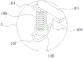
FIG. 3 is an enlarged view of a portion of the structure at A in FIG. 2;
FIG. 4 is a left side view of the structure of FIG. 1;
FIG. 5 is an enlarged view of a portion of the structure shown at B in FIG. 4;
in the drawings, the components represented by the respective reference numerals are listed below:
1-bottom plate, 101-rectangular frame, 102-sliding clamping groove, 103-supporting rod, 104-movable plate, 105-spring, 106-supporting block, 107-pull ring, 108-mounting plate, 109-driving motor, 110-bidirectional threaded rod, 111-first limiting hole, 112-leg pressing rod, 113-leg supporting cushion, 114-first fastening bolt, 115-rotary plate, 116-loop rod, 117-lifting rod, 118-second threaded groove, 119-second limiting hole, 120-second fastening bolt, 121-supporting plate, 122-anti-slip strip, 123-sliding groove, 124-upright post, 125-supine supporting part, 126-co-location threaded hole, 127-third fastening bolt and 128-loop foot limiting ring.
Detailed Description
The technical solutions in the embodiments of the present invention will be described clearly and completely with reference to the accompanying drawings in the embodiments of the present invention, and it is obvious that the described embodiments are only some embodiments of the present invention, not all embodiments. Based on the embodiments of the present invention, all other embodiments obtained by a person of ordinary skill in the art without creative efforts belong to the protection scope of the present invention.
Referring to fig. 1-5, the utility model relates to a novel multipurpose exercise device for aerobics exercises, which comprises a bottom plate 1 and a rectangular frame 101;
the bottom of the rectangular frame 101 is fixedly connected with the upper surface of the bottom plate 1;
a sliding clamping groove 102 is formed in one side surface of the rectangular frame 101, close to the top; a support rod 103 is fixedly connected inside the sliding clamping groove 102 through a sliding block; one end of the supporting rod 103 is hinged with a movable plate 104; the bottom of the movable plate 104 is fixedly connected with a spring 105; one end of the spring 105 is fixedly connected with a supporting block 106; the circumferential side surface of the supporting block 106 is fixedly connected with a pull ring 107, the pull ring 107 is operated, and the arm is exercised by the elastic expansion force of the spring 105;
one side of the rectangular frame 101 is symmetrically and fixedly connected with a mounting plate 108; a driving motor 109 is fixedly arranged on one side surface of the mounting plate 108; the output end of the driving motor 109 is fixedly connected with a bidirectional threaded rod 110; one end of the bidirectional threaded rod 110 penetrates through one side surface of the supporting rod 103, and is rotatably connected with one side surface of the other mounting plate 108; the drive motor 109 drives the bidirectional threaded rod 110 to rotate, so that the two support rods 103 synchronously move in the opposite direction along the bidirectional threaded rod 110, the distance between the two support rods 103 can be flexibly adjusted, the adjustment can be carried out according to the distance between two arms of a user, and the requirements of different users can be met.
As shown in fig. 1-2, a plurality of first limiting holes 111 are formed on an opposite inner side surface of the rectangular frame 101; a leg pressing rod 112 is attached to the outer part of the first limiting hole 111; one end of the leg pressing rod 112 is fixedly connected with a leg supporting cushion 113, and the leg supporting cushion 113 plays a role in buffering and pressure reduction, so that the injury of legs during exercise and stretching is reduced, and the comfort of the legs is improved; one end of the leg pressing rod 112 is provided with a first thread groove 114; the inner wall of the first thread groove 114 and the inner wall of the first limiting hole 111 are in thread fit with a first fastening bolt 115, and the height of the leg pressing rod 112 can be adjusted through the first fastening bolt 115, so that the requirements of users with different heights are met.
As shown in fig. 2 and 5, a rotary plate 116 is rotatably connected to the upper surface of the bottom plate 1; the upper surface of the turntable 116 is fixedly connected with a loop bar 117, and the inner wall of the loop bar 117 is connected with a lifting rod 118 in a sliding manner; the peripheral side surface of the lifting rod 118 and the peripheral side surface of the loop bar 117 are respectively provided with a second thread groove 119 and a second limit hole 120; a second fastening bolt 121 is in threaded fit with the inner wall of the second thread groove 119 and the inner wall of the second limiting hole 120; one end of the lifting rod 118 is fixedly connected with a supporting plate 122; the upper surface of the supporting plate 122 is fixedly connected with a plurality of anti-skid strips 123; through the cooperation use of lifter 118 and second fastening bolt 121, can carry out the regulation of backup pad 122 height according to the user's height condition, make the user touch pull ring 107 with the help of backup pad 122 to realize the purpose of tempering.
As shown in fig. 4-5, the upper surface of the bottom plate 1 is provided with a chute 124; the inside of the chute 124 is connected with a column 125 in a sliding way; a supine supporting component 126 is fixedly connected to the top of the upright post 125; a side face opposite to the sliding groove 124 and a side face opposite to the upright post 125 are both provided with a homotopic threaded hole 127; the third fastening bolt 128 is screwed in the apposition screw hole 127; the upper surface of the bottom plate 1 is fixedly connected with a foot-sleeving limiting ring 129; the foot-covering limiting ring 129 is positioned between the two sliding grooves 124; the pillar 125 is slid along the slide groove 124 to be moved to a proper position according to the height of the user who needs to perform abdominal exercise, and is fixed by the third fastening bolt 128.
The working principle of the embodiment is as follows: firstly, when a body-building exerciser needs to exercise the legs and the arms at the same time, the user can hold the pull ring 107 by hand, pull the spring 105, exercise the arms of the body-building exerciser by utilizing the elastic expansion force of the spring 105, meanwhile, place the legs of the exerciser on the leg supporting cushion 113 on the leg pressing rod 112, and simultaneously exercise the legs and the arms of the body-building exerciser by matching with the spring 105, when the exerciser is small in body, the user can adjust the leg pressing rod 112 to the height required by the exerciser by downward adjusting the first fastening bolt 114 so as to achieve the optimal exercise position; then, when the body building exerciser needs to exercise the waist, the exerciser can stand on the support plate 121 provided with the anti-slip strips 122, the pull ring 107 is controlled by both hands, the support plate 121 can be rotated by foot strength while arm strength is exercised, and waist exercise of the body building exerciser is realized, similarly, when the exerciser is small in size, the height of the support plate 121 needs to be adjusted, the second fastening bolt 120 can be adjusted upwards, the position of the lifting rod 117 is adjusted to be high, so that the height adjustment of the support plate 121 is realized, and the body building exerciser with small size can stand on the support plate 121 to perform control operation of the pull ring 107 so as to exercise the waist; finally, when the body building exerciser needs to do the abdominal exercise, the exerciser can insert both feet into the foot-covering limiting ring 128, lean the back against the supine support component 125 to do the sit-up exercise, so as to realize the abdominal exercise of the exerciser, when the exerciser is high in stature, the exerciser needs to adjust the position of the supine support component 125, move the upright post 124 along the sliding groove 123, adjust the supine support component 125 to a proper position, and fix the supine support component 125 by using the third fastening bolt 127, so as to realize the best abdominal exercise effect.
In the description herein, references to the description of "one embodiment," "an example," "a specific example," etc., mean that a particular feature, structure, material, or characteristic described in connection with the embodiment or example is included in at least one embodiment or example of the invention. In this specification, the schematic representations of the terms used above do not necessarily refer to the same embodiment or example. Furthermore, the particular features, structures, materials, or characteristics described may be combined in any suitable manner in any one or more embodiments or examples.
The preferred embodiments of the present invention disclosed above are intended only to help illustrate the present invention. The preferred embodiments are not intended to be exhaustive or to limit the invention to the precise embodiments disclosed. Obviously, many modifications and variations are possible in light of the above teaching. The embodiments were chosen and described in order to best explain the principles of the invention and its practical applications, to thereby enable others skilled in the art to best understand the invention for and utilize the invention. The present invention is limited only by the claims and their full scope and equivalents.
Claims (8)
1. A novel multipurpose exercise device for aerobics exercises comprises a base plate (1) and a rectangular frame (101); the method is characterized in that:
the bottom of the rectangular frame (101) is fixedly connected with the upper surface of the bottom plate (1);
a sliding clamping groove (102) is formed in one side surface of the rectangular frame (101) close to the top; the inside of the sliding clamping groove (102) is fixedly connected with a supporting rod (103) through a sliding block; one end of the supporting rod (103) is hinged with a movable plate (104); the bottom of the movable plate (104) is fixedly connected with a spring (105); one end of the spring (105) is fixedly connected with a supporting block (106); the circumferential side surface of the supporting block (106) is fixedly connected with a pull ring (107);
a mounting plate (108) is symmetrically and fixedly connected to one side surface of the rectangular frame (101); a driving motor (109) is fixedly arranged on one side surface of the mounting plate (108); the output end of the driving motor (109) is fixedly connected with a bidirectional threaded rod (110); one end of the bidirectional threaded rod (110) penetrates through one side surface of the supporting rod (103), and the end is rotatably connected with one side surface of the other mounting plate (108).
2. A novel multipurpose exercise device for aerobics exercises as claimed in claim 1, wherein a plurality of first limiting holes (111) are formed on one opposite inner side surface of the rectangular frame (101); a leg pressing rod (112) is attached to the outer part of the first limiting hole (111); one end of the leg pressing rod (112) is fixedly connected with a leg supporting cushion (113).
3. The novel multipurpose exercise device for aerobics exercises as claimed in claim 2, wherein one end of the leg pressing rod (112) is provided with a first thread groove; and a first fastening bolt (114) is in threaded fit with the inner wall of the first thread groove and the inner wall of the first limiting hole (111).
4. A novel aerobics multipurpose exercise device as claimed in claim 1, wherein the upper surface of the base plate (1) is rotatably connected with a rotary disc (115); the upper surface of the turntable (115) is fixedly connected with a sleeve rod (116), and the inner wall of the sleeve rod (116) is connected with a lifting rod (117) in a sliding manner; a second thread groove (118) and a second limit hole (119) are respectively formed on the peripheral side surface of the lifting rod (117) and the peripheral side surface of the sleeve rod (116); and a second fastening bolt (120) is in threaded fit with the inner wall of the second thread groove (118) and the inner wall of the second limiting hole (119).
5. A novel aerobics multi-purpose exercise device as claimed in claim 4, wherein one end of said lifting bar (117) is fixedly connected with a support plate (121); the upper surface of the supporting plate (121) is fixedly connected with a plurality of anti-slip strips (122).
6. A novel aerobics multipurpose exercise device as claimed in claim 1, wherein the upper surface of the base plate (1) is provided with a chute (123); the inside of the sliding groove (123) is connected with an upright post (124) in a sliding manner; the top of the upright post (124) is fixedly connected with a supine supporting component (125).
7. A novel aerobics exercises multipurpose exercise device of claim 6, wherein one opposite side of the sliding groove (123) and one opposite side of the upright post (124) are provided with homotopic threaded holes (126); and a third fastening bolt (127) is in threaded fit with the inner part of the apposition threaded hole (126).
8. The novel aerobics exercises multipurpose exercise device according to claim 7, wherein a foot-covering limiting ring (128) is fixedly connected to the upper surface of the bottom plate (1); the foot-covering limiting ring (128) is positioned between the two sliding grooves (123).
Priority Applications (1)
| Application Number | Priority Date | Filing Date | Title |
|---|---|---|---|
| CN202021694650.8U CN213159192U (en) | 2020-08-14 | 2020-08-14 | Novel multi-purpose exercise of aerobics exercises device |
Applications Claiming Priority (1)
| Application Number | Priority Date | Filing Date | Title |
|---|---|---|---|
| CN202021694650.8U CN213159192U (en) | 2020-08-14 | 2020-08-14 | Novel multi-purpose exercise of aerobics exercises device |
Publications (1)
| Publication Number | Publication Date |
|---|---|
| CN213159192U true CN213159192U (en) | 2021-05-11 |
Family
ID=75800625
Family Applications (1)
| Application Number | Title | Priority Date | Filing Date |
|---|---|---|---|
| CN202021694650.8U Expired - Fee Related CN213159192U (en) | 2020-08-14 | 2020-08-14 | Novel multi-purpose exercise of aerobics exercises device |
Country Status (1)
| Country | Link |
|---|---|
| CN (1) | CN213159192U (en) |
-
2020
- 2020-08-14 CN CN202021694650.8U patent/CN213159192U/en not_active Expired - Fee Related
Similar Documents
| Publication | Publication Date | Title |
|---|---|---|
| US7578774B1 (en) | Resistance exercise machine | |
| CN210096817U (en) | A sitting posture divides leg body-building device for shank muscle | |
| GB2391180A (en) | Yoga balance trainer | |
| CN111282198B (en) | High-difficulty body-building operation correcting training device | |
| CN211158508U (en) | Multipurpose training device for aerobics exercises | |
| CN112316380A (en) | Multi-functional aerobics exercises physique training teaching device | |
| CN109939414A (en) | A kind of physical training device | |
| CN111672053B (en) | Sitting and lying type multifunctional body-building rehabilitation machine | |
| CN112891850A (en) | Physical training device capable of relieving anxiety psychology | |
| CN211798629U (en) | Aerobics exercises is with crooked training auxiliary device | |
| CN213159192U (en) | Novel multi-purpose exercise of aerobics exercises device | |
| CN214105781U (en) | Training device for aerobics exercises | |
| CN105582644A (en) | Arm strength pushing and pressing exercise equipment | |
| CN205412147U (en) | Day word is towards fast arm ware of fist | |
| CN211535464U (en) | Novel multi-functional upper limbs rehabilitation training device | |
| CN204034137U (en) | Both arms pushing exercising machine | |
| CN201164684Y (en) | Sport body-building apparatus | |
| CN210078735U (en) | Fitness equipment is used in sports training | |
| CN202751744U (en) | Multifunctional fitness device | |
| CN110898395A (en) | Leg strength exercise equipment for fitness and using method thereof | |
| CN220676646U (en) | Sit-up body-building apparatus | |
| CN215461791U (en) | Novel multi-purpose exercise of aerobics exercises device | |
| CN213964999U (en) | Multifunctional sports equipment | |
| CN204050834U (en) | Twoly push away weight training exercise device | |
| CN204034183U (en) | Twoly push away drill rack |
Legal Events
| Date | Code | Title | Description |
|---|---|---|---|
| GR01 | Patent grant | ||
| GR01 | Patent grant | ||
| CF01 | Termination of patent right due to non-payment of annual fee | ||
| CF01 | Termination of patent right due to non-payment of annual fee |
Granted publication date: 20210511 Termination date: 20210814 |