CN213133483U - Raw material crushing device for additive - Google Patents
Raw material crushing device for additive Download PDFInfo
- Publication number
- CN213133483U CN213133483U CN202021488163.6U CN202021488163U CN213133483U CN 213133483 U CN213133483 U CN 213133483U CN 202021488163 U CN202021488163 U CN 202021488163U CN 213133483 U CN213133483 U CN 213133483U
- Authority
- CN
- China
- Prior art keywords
- crushing
- roller
- box body
- motor
- additive
- Prior art date
- Legal status (The legal status is an assumption and is not a legal conclusion. Google has not performed a legal analysis and makes no representation as to the accuracy of the status listed.)
- Active
Links
Images

Abstract
A raw material crushing device for an additive comprises a crushing box body 1, a crushing roller 2, a rolling roller 5, a support frame 6, a sieve plate 7 and a material collecting groove 14, wherein the support frame 6 is fixedly connected to the crushing box body 1, a feed inlet 15 is formed in the top of the crushing box body 1, the crushing roller 2 is arranged inside the crushing box body 1, a crushing knife 3 is welded on the surface of the crushing roller 2, the crushing roller 2 is fixedly connected to a first motor 16, the first motor 16 is connected to the front surface of the crushing box body 1 through bolts, a material guide plate 4 is arranged at the bottom of the crushing roller 2, the material guide plate 4 is fixedly connected to the inner wall of the crushing box body 1, the rolling roller 5 is arranged below the material guide plate 4, the rolling roller 5 is connected to a second motor 17, the second motor 17 is connected to the front surface of the crushing box body 1 through bolts, the second motor 17, the sieve plate 7 is arranged under the discharge hole 19, and a filter screen 18 is arranged at the center of the sieve plate 7.
Description
Technical Field
The utility model relates to a raw materials processing technology field, in particular to raw materials reducing mechanism of additive.
Background
Need refine the quality that promotes the aluminum alloy at the aluminum alloy smelting in-process, instant silicon just one of the refining agent that needs to add, and instant silicon is the cubic, need add the use to its shredding just, but current equipment is not thorough when smashing instant silicon and grinding, can produce cubic impurity etc. has reduced the smelting effect of aluminum alloy, can't make it reach required requirement.
SUMMERY OF THE UTILITY MODEL
The utility model mainly aims to provide a raw material crushing device for additives, which overcomes the defects in the prior art;
in order to solve the technical problem, the utility model provides a following technical scheme:
a raw material crushing device for an additive comprises a crushing box body, a crushing roller, a rolling roller, a support frame, a sieve plate and a material collecting groove, wherein the support frame is fixedly connected with the crushing box body, a feed inlet is formed in the top of the crushing box body, the crushing roller is arranged inside the crushing box body, a crushing knife is welded on the surface of the crushing roller, the crushing roller is fixedly connected to a first motor, the first motor is connected to the front surface of the crushing box body through bolts, a material guide plate is arranged at the bottom of the crushing roller and fixedly connected to the inner wall of the crushing box body, the rolling roller is arranged below the material guide plate, the material guide plate can guide the additive crushed by the crushing roller into the position right above the rolling roller for secondary crushing processing, the rolling roller is connected to a second motor, the second motor is connected to the front surface of the crushing box body through bolts, the second, the screen plate is arranged under the discharge port, a filter screen is arranged in the center of the screen plate, sliding grooves are formed in two ends of the front surface and the rear surface of the screen plate, a motor III is arranged on two sides of the bottom of the screen plate and is connected with a support frame through a bolt, an eccentric wheel is connected with the motor III, an eccentric connecting piece is arranged on the surface of the eccentric wheel and is coupled to the bottom of the screen plate, the eccentric connecting piece is driven by the motor III to drive the eccentric connecting piece to enable the screen plate to shake to screen materials, a supporting rod is arranged on one side, close to the outer side, of the motor III, the supporting rod is fixedly connected to the support frame, the top of the supporting rod is connected to a sliding block, the sliding block is connected to the;
optionally, the two crushing rollers are arranged and symmetrically distributed by taking the axis of the crushing box body as a center;
optionally, the two guide plates are arranged and are distributed in an inclined symmetrical manner, the edge of each guide plate is positioned right above the rolling roller, and after the additives are crushed by the crushing roller, the additives are guided to the position above the rolling roller through the guide plates and fall onto the rolling roller for further rolling and grinding, so that the fineness of the additives is further improved;
optionally, the rolling rollers are provided with two rolling rollers and symmetrically arranged under the crushing rollers, and the gap between the rolling rollers is smaller than the gap between the crushing rollers, so that the crushed additive can be further rolled and ground;
optionally, the bottom of the crushing box body is funnel-shaped;
optionally, the front surface of the material collecting groove is connected with a handle, and the material collecting groove filled with the additives can be drawn out through the handle;
optionally, four support rods and four slide blocks are arranged, so that the stability of the sieve plate can be ensured in the process of shaking and sieving the sieve plate by the three pairs of sieve plates through the motor;
has the advantages that: the utility model discloses a surface is equipped with crushing roller and the roller that rolls of smashing the sword smashes the additive piece that adds in proper order, grinding process obtains the tiny granule of meticulous additive or even powder, and the additive after the help is smashed under the effect of stock guide is leading-in to carry out the secondary operation grinding in rolling the roller, additive raw materials after the grinding still can be through the final screening of sieve, the sieve shakes the screening to the raw materials under the effect of motor three and eccentric wheel, the additive raw materials that will reach the requirement finally concentrates on the groove that gathers materials, moreover, the steam generator is simple and reasonable in structure, it is fabulous to the crushing effect of raw materials, can obtain meticulous additive raw materials and carry out aluminum alloy refining, guarantee refining quality, whole crushing effect is fabulous and is worth promoting.
Drawings
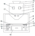
FIG. 1 is a schematic structural view of the present invention;
FIG. 2 is a schematic view of the front view of the structure of the present invention;
the device comprises a crushing box body 1, a crushing roller 2, a crushing cutter 3, a guide plate 4, a rolling roller 5, a support frame 6, a sieve plate 7, a chute 8, a motor III, an eccentric wheel 10, an eccentric connecting piece 11, a sliding block 12, a supporting rod 13, a material collecting groove 14, a feeding port 15, a motor I16, a motor II 17, a filter screen 18 and a discharging port 19.
Detailed Description
The technical solution of the present invention will be described clearly and completely with reference to the accompanying drawings, and obviously, the described embodiments are some, but not all embodiments of the present invention. Based on the embodiments in the present invention, all other embodiments obtained by a person skilled in the art without creative work belong to the protection scope of the present invention.
In the description of the present invention, it is to be noted that, unless otherwise explicitly specified or limited, the terms "mounted," "connected," and "connected" are to be construed broadly, and may be, for example, fixedly connected, detachably connected, or integrally connected; can be mechanically or electrically connected; they may be connected directly or indirectly through intervening media, or they may be interconnected between two elements. The specific meaning of the above terms in the present invention can be understood in specific cases by those skilled in the art.
As shown in fig. 1-2, the device comprises a crushing box body 1, a crushing roller 2, a rolling roller 5, a support frame 6, a sieve plate 7 and a material collecting groove 14, wherein the support frame 6 is fixedly connected to the crushing box body 1, a feed inlet 15 is formed in the top of the crushing box body 1, the crushing roller 2 is arranged inside the crushing box body 1, a crushing knife 3 is welded on the surface of the crushing roller 2, the crushing roller 2 is fixedly connected to a motor I16, the motor I16 is connected to the front surface of the crushing box body 1 through a bolt, a material guide plate 4 is arranged at the bottom of the crushing roller 2, the material guide plate 4 is fixedly connected to the inner wall of the crushing box body 1, the rolling roller 5 is arranged below the material guide plate 4, the material guide plate can guide additives crushed by the crushing roller into the material right above the rolling roller for secondary crushing processing, the rolling roller 5 is connected to a motor, the second motor 17 is arranged below the first motor 16, a discharge hole 19 is arranged under the rolling roller 5, the sieve plate 7 is arranged under the discharge hole 19, a filter screen 18 is arranged at the center of the sieve plate 7, sliding grooves 8 are formed in two ends of the front surface and the rear surface of the sieve plate 7, a third motor 9 is arranged on two sides of the bottom of the sieve plate 7, the third motor 9 is connected to the support frame 6 through bolts, the third motor 9 is connected with an eccentric wheel 10, an eccentric connecting piece 11 is arranged on the surface of the eccentric wheel 10, the eccentric connecting piece 11 is connected to the bottom of the sieve plate 7 in a shaft coupling mode, the eccentric connecting piece is driven by the third motor to enable the sieve plate to shake materials, a support rod 13 is arranged on one outer side of the third motor 9, the support rod 13 is fixedly connected to the support frame 6, the top of the support rod 13 is connected to a sliding block, the material collecting groove 14 is arranged right below the bottom of the sieve plate 7; the two crushing rollers 2 are arranged and symmetrically distributed by taking the axis of the crushing box body 1 as the center; the two guide plates 4 are arranged and are obliquely and symmetrically distributed, the edge of each guide plate 4 is positioned right above the rolling roller 5, and after being crushed by the crushing roller, the additive is guided to the position above the rolling roller through the guide plates and falls onto the rolling roller for further rolling and grinding, so that the fineness of the additive is further improved; the grinding rollers 5 are provided with two grinding rollers and symmetrically arranged under the grinding rollers 2, the gap between the grinding rollers 5 is smaller than the gap between the grinding rollers 2, and grinding can be further carried out on the ground additives; the bottom of the crushing box body 1 is funnel-shaped; the front surface of the material collecting groove 14 is connected with a handle, and the material collecting groove filled with additives can be drawn out through the handle; bracing piece 13 and slider 12 all are equipped with four, can guarantee that the motor is three to the sieve shake sieve material in-process guarantees sieve stability.
The working principle is as follows: when the device is used, a first motor 16, a second motor 17 and a third motor 9 are turned on, the crushing roller 2 and the rolling roller 5 start to rotate, the eccentric wheel 10 is driven by the third motor 9 to drive the eccentric connecting piece 11 to rotate so that the sieve plate 7 shakes, then the sieve plate 7 slides with the sliding block 12 through the sliding groove 8, the supporting rod 13 ensures the stable operation of the sieve plate 7 through the sliding block 12, at the moment, the block-shaped additive raw material is added through the feeding port 15, the raw material is firstly crushed through the crushing roller 2, the block-shaped raw material is cut and crushed into small blocks by the crushing knife 3, the preliminarily crushed raw material falls onto the guide plate 4 and slides to the position right above the rolling roller 5 along the downward inclined main body of the guide plate and is rolled and ground through the rolling roller 5, then the raw material falls onto the sieve plate 7 through the discharging port and is filtered through the filter screen 18 arranged on the surface of the shaken sieve plate 7, the catch basin 14 can be pulled out by the handle after being excessively piled up.
Claims (7)
1. The raw material crushing device for the additive is characterized in that: comprises a crushing box body (1), a crushing roller (2), a rolling roller (5), a support frame (6), a sieve plate (7) and a material collecting groove (14), wherein the support frame (6) is fixedly connected with the crushing box body (1), a feed inlet (15) is formed in the top of the crushing box body (1), the crushing roller (2) is arranged inside the crushing box body (1), a crushing knife (3) is welded on the surface of the crushing roller (2), the crushing roller (2) is fixedly connected with a first motor (16), the first motor (16) is in bolted connection with the front surface of the crushing box body (1), a guide plate (4) is arranged at the bottom of the crushing roller (2), the guide plate (4) is fixedly connected with the inner wall of the crushing box body (1), the rolling roller (5) is arranged below the guide plate (4), the rolling roller (5) is connected with a second motor (17), and the second motor (17) is in bolted connection with the front surface, the utility model discloses a sieve plate, including sieve plate (7), sieve (7), motor two (17), grinding roller (5), sieve (7), filter screen (10), eccentric connecting piece (11) hub connection in sieve (7) bottom, motor three (9) is equipped with bracing piece (13) by outer one side, bracing piece (13) fixed connection in support frame (6), bracing piece (13) top is connected in slider (12), slider (12) sliding connection is in spout (8), material collecting tank (14) are located under sieve (7) bottom.
2. The apparatus for pulverizing an additive as claimed in claim 1, wherein: the two crushing rollers (2) are arranged and symmetrically distributed by taking the axis of the crushing box body (1) as the center.
3. The apparatus for pulverizing an additive as claimed in claim 1, wherein: the two material guide plates (4) are arranged and are distributed in an inclined and symmetrical mode, and the edges of the material guide plates (4) are located right above the rolling rollers (5).
4. The apparatus for pulverizing an additive as claimed in claim 1, wherein: roll roller (5) and be equipped with two altogether and the symmetry is located and is smashed under roller (2), the clearance between rolling roller (5) is less than the clearance between smashing roller (2).
5. The apparatus for pulverizing an additive as claimed in claim 1, wherein: the bottom of the crushing box body (1) is funnel-shaped.
6. The apparatus for pulverizing an additive as claimed in claim 1, wherein: the front surface of the material collecting groove (14) is connected with a handle.
7. The apparatus for pulverizing an additive as claimed in claim 1, wherein: the number of the support rods (13) and the number of the slide blocks (12) are four.
Priority Applications (1)
| Application Number | Priority Date | Filing Date | Title |
|---|---|---|---|
| CN202021488163.6U CN213133483U (en) | 2020-07-24 | 2020-07-24 | Raw material crushing device for additive |
Applications Claiming Priority (1)
| Application Number | Priority Date | Filing Date | Title |
|---|---|---|---|
| CN202021488163.6U CN213133483U (en) | 2020-07-24 | 2020-07-24 | Raw material crushing device for additive |
Publications (1)
| Publication Number | Publication Date |
|---|---|
| CN213133483U true CN213133483U (en) | 2021-05-07 |
Family
ID=75733022
Family Applications (1)
| Application Number | Title | Priority Date | Filing Date |
|---|---|---|---|
| CN202021488163.6U Active CN213133483U (en) | 2020-07-24 | 2020-07-24 | Raw material crushing device for additive |
Country Status (1)
| Country | Link |
|---|---|
| CN (1) | CN213133483U (en) |
Cited By (1)
| Publication number | Priority date | Publication date | Assignee | Title |
|---|---|---|---|---|
| CN113578433A (en) * | 2021-06-09 | 2021-11-02 | 珠海宏嘉投资有限公司 | Extraction device for effectively improving magnetic field substance by black jade and application method |
-
2020
- 2020-07-24 CN CN202021488163.6U patent/CN213133483U/en active Active
Cited By (1)
| Publication number | Priority date | Publication date | Assignee | Title |
|---|---|---|---|---|
| CN113578433A (en) * | 2021-06-09 | 2021-11-02 | 珠海宏嘉投资有限公司 | Extraction device for effectively improving magnetic field substance by black jade and application method |
Similar Documents
| Publication | Publication Date | Title |
|---|---|---|
| CN209753022U (en) | Chemical products processing is with smashing sieving mechanism | |
| CN213194012U (en) | Recycled concrete waste recovery device | |
| CN210079645U (en) | Industrial solid waste crushing device | |
| CN213133483U (en) | Raw material crushing device for additive | |
| CN115739274A (en) | Pet food raw materials breaker | |
| CN216654810U (en) | Be used for sea cucumber peptide production and processing to use raw materials reducing mechanism | |
| CN214916596U (en) | Efficient nepheline ore deposit automatic filtration screening edulcoration equipment | |
| CN212237476U (en) | Mineral separation production and processing is with grinding ore device | |
| CN213590621U (en) | Broken milling machine | |
| CN211359513U (en) | Combined rotary filter screen | |
| CN212189496U (en) | Building stone smashing device | |
| CN210207151U (en) | Fine crushing device for three-section tailing discarding process | |
| CN212018025U (en) | Carragheen milling equipment | |
| CN210621314U (en) | Rubbing crusher is used in paper mill | |
| CN211726034U (en) | Konjak smashing device convenient to screen | |
| CN210729727U (en) | Waste paper crushing and recycling device | |
| CN219308922U (en) | Efficient coal washing device for coal mining | |
| CN217910783U (en) | Adjust buddha's warrior attendant thorn rubbing crusher of crushing degree | |
| CN220590264U (en) | Fine fodder grinder | |
| CN216826582U (en) | Breaker is used in aerogel powder production | |
| CN219663915U (en) | Sieve flitch for rubbing crusher | |
| CN218531212U (en) | Feed ingredient rubbing crusher | |
| CN217774356U (en) | Iron scale recovery plant | |
| CN219596876U (en) | Rubber auxiliary agent reducing mechanism for rubber production | |
| CN220759359U (en) | Production raw material grinding device |
Legal Events
| Date | Code | Title | Description |
|---|---|---|---|
| GR01 | Patent grant | ||
| GR01 | Patent grant |