CN213111347U - Automatic centering feed mechanism - Google Patents
Automatic centering feed mechanism Download PDFInfo
- Publication number
- CN213111347U CN213111347U CN202021627434.1U CN202021627434U CN213111347U CN 213111347 U CN213111347 U CN 213111347U CN 202021627434 U CN202021627434 U CN 202021627434U CN 213111347 U CN213111347 U CN 213111347U
- Authority
- CN
- China
- Prior art keywords
- fixed
- plate
- centering
- fixed plate
- electric telescopic
- Prior art date
- Legal status (The legal status is an assumption and is not a legal conclusion. Google has not performed a legal analysis and makes no representation as to the accuracy of the status listed.)
- Active
Links
Images


Abstract
The utility model discloses an automatic centering feed mechanism relates to feed mechanism technical field, for solving current material or other materials when using the conveyer belt to carry the feeding, the material is scattered all around easily, can not fine along the problem of central line motion. Side installation fixed plate is all installed to the both sides of carrying the conveyer belt frame, centering feed mechanism installation body frame is installed to the top of side installation fixed plate, the connection dead lever is all installed to the both sides of centering feed mechanism installation body frame below, the below of connecting the dead lever is installed and is assisted the mounting panel, spacing fixed plate is installed to the inboard one end of supplementary mounting panel, electric telescopic handle is installed to spacing fixed plate below.
Description
Technical Field
The utility model relates to a feed mechanism technical field specifically is an automatic centering feed mechanism.
Background
The design of the feeding mechanism in the automatic production is determined according to the functional requirements of feeding and the supply condition of materials. The feed function generally requires simultaneous completion of the feed before the process push and the discharge after the completion. The supply state of the materials is bulk, arranged in series into a roll or folded; the raw material supply is of strand, strip or plate material, etc. The automatic feeding of bulk cargo is completed by a common vibration disc, but most of feeding actions need to adopt a comprehensive mechanism consisting of a plurality of simple mechanisms and are realized through various motion transformations.
However, when the existing materials or other materials are conveyed and fed by using a conveyor belt, the materials are easily scattered and cannot well move along the center line; therefore, the existing requirements are not met, and an automatic centering feeding mechanism is provided for the requirement.
SUMMERY OF THE UTILITY MODEL
An object of the utility model is to provide an automatic centering feed mechanism to current material or other materials that provide in solving above-mentioned background art are when using the conveyer belt to carry the feeding, and the material is scattered all around easily, can not fine along the problem of central line motion.
In order to achieve the above object, the utility model provides a following technical scheme: the utility model provides an automatic centering feed mechanism, includes the transport conveyer belt frame, side installation fixed plate is all installed to the both sides of transport conveyer belt frame, centering feed mechanism installation body frame is installed to the top of side installation fixed plate, the connection dead lever is all installed to the both sides of centering feed mechanism installation body frame below, connect the below of dead lever and install supplementary mounting panel, spacing fixed plate is installed to the inboard one end of supplementary mounting panel, electric telescopic handle is installed to spacing fixed plate below.
Preferably, the side installation fixed plate passes through bolted connection with the transport conveyer belt frame, centering feed mechanism installation body frame passes through bolted connection with the side installation fixed plate, supplementary mounting panel passes through bolted connection with the connection dead lever.
Preferably, the auxiliary mounting plate passes through connecting block fixed connection with spacing fixed plate, the guide swash plate is installed to electric telescopic handle's inboard, fixed link rod is installed in the outside of guide swash plate, and fixed link rod and guide swash plate fixed connection, fixed link rod passes through electric rotating shaft with electric telescopic handle and rotates and be connected.
Preferably, second electric telescopic handle is installed to electric telescopic handle's below, centering fixed plate is installed to second electric telescopic handle's inboard, and centering fixed plate passes through the screw connection with second electric telescopic handle, step motor is installed to the one end in the auxiliary mounting panel outside.
Preferably, the middle position below the centering feeding mechanism mounting main frame is provided with an upper fixing telescopic rod, the lower part of the upper fixing telescopic rod is provided with a height limiting plate, and the upper fixing telescopic rod is connected with the height limiting plate and the centering feeding mechanism mounting main frame through screws.
Preferably, the internally mounted of spacing fixed plate has the rotation toothed disc, the upper end of rotating the toothed disc is provided with the slip fixed slot, the internally mounted of slip fixed slot has the fixed sliding plate, the telescopic link connecting plate is installed to the rear end of fixed sliding plate, and telescopic link connecting plate and second electric telescopic handle fixed connection, step motor's output shaft and rotation toothed disc transmission are connected.
Preferably, the lower extreme of fixed sliding plate is provided with the cooperation driving gear, and the cooperation driving gear is provided with a plurality of, and a plurality of cooperation driving gear distributes in proper order, the cooperation driving gear is connected with the meshing of rotation gear dish.
Compared with the prior art, the beneficial effects of the utility model are that:
1. the utility model discloses an install spacing fixed plate, guide swash plate and centering fixed plate, can carry out the regulation of guide angle through the guide swash plate, can carry out certain regulation according to the angle of the different centering of size difference of material, can guarantee centering performance to the intermediate motion through centering fixed plate, solved current material or other materials when using the conveyer belt to carry the feeding, the material is easy to scatter, can not fine along the problem of central line motion;
2. the utility model discloses an install rotation toothed disc and fixed sliding plate, can drive through step motor's output shaft and rotate the toothed disc, can make fixed sliding plate lateral motion through the rotation of rotating the toothed disc, can carry out certain regulation to second electric telescopic handle's position, can adjust after adjusting the inclination, ensure the performance of laminating guide.
Drawings
Fig. 1 is a top view of an automatic centering feeding mechanism of the present invention;
FIG. 2 is a front view of the centering and feeding mechanism mounting main frame of the present invention;
fig. 3 is a schematic view of the internal structure of the auxiliary mounting plate of the present invention.
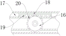
In the figure: 1. a conveyor belt rack; 2. a fixing plate is arranged on the side edge; 3. the centering feeding mechanism is provided with a main frame; 4. an auxiliary mounting plate; 5. a limiting fixing plate; 6. connecting blocks; 7. a material guiding inclined plate; 8. an electric telescopic rod; 9. a fixed connecting rod; 10. an electric rotating shaft; 11. a second electric telescopic rod; 12. a stepping motor; 13. centering the fixed plate; 14. an expansion link is fixed on the upper part; 15. a height limiting plate; 16. rotating the gear plate; 17. a sliding fixing groove; 18. fixing the sliding plate; 19. matching with a transmission gear; 20. the telescopic rod is connected with the plate; 21. and connecting the fixing rod.
Detailed Description
The technical solutions in the embodiments of the present invention will be described clearly and completely with reference to the accompanying drawings in the embodiments of the present invention, and it is obvious that the described embodiments are only some embodiments of the present invention, not all embodiments.
Referring to fig. 1-3, the present invention provides an embodiment: the utility model provides an automatic centering feed mechanism, including carrying conveyer belt frame 1, side installation fixed plate 2 is all installed to the both sides of carrying conveyer belt frame 1, centering feed mechanism installation body frame 3 is installed to the top of side installation fixed plate 2, connection dead lever 21 is all installed to the both sides of 3 below of centering feed mechanism installation body frame, auxiliary mounting panel 4 is installed to the below of connecting dead lever 21, spacing fixed plate 5 is installed to the inboard one end of auxiliary mounting panel 4, electric telescopic handle 8 is installed to spacing fixed plate 5 below, the flexibility performance of guarantee centering that can be better, it saves trouble to adjust more convenient.
Further, side installation fixed plate 2 passes through bolted connection with transport conveyer belt frame 1, and centering feed mechanism installation body frame 3 passes through bolted connection with side installation fixed plate 2, and supplementary mounting panel 4 passes through bolted connection with being connected dead lever 21, and convenient and fast more is dismantled in the installation, and holistic performance is more stable perfect.
Further, auxiliary mounting panel 4 passes through connecting block 6 fixed connection with spacing fixed plate 5, and guide swash plate 7 is installed to electric telescopic handle 8's inboard, and fixed connecting rod 9 is installed in the outside of guide swash plate 7, and fixed connecting rod 9 and guide swash plate 7 fixed connection, and fixed connecting rod 9 rotates through electric rotating shaft 10 with electric telescopic handle 8 to be connected, and pivoted stability is higher.
Further, second electric telescopic handle 11 is installed to electric telescopic handle 8's below, and centering fixed plate 13 is installed to second electric telescopic handle 11's inboard, and centering fixed plate 13 passes through the screw connection with second electric telescopic handle 11, and step motor 12 is installed to the one end in the auxiliary mounting panel 4 outside, guarantee structure's that can be better performance.
Further, the intermediate position department of 3 below of centering feed mechanism installation body frames installs fixed telescopic link 14, goes up the below of fixed telescopic link 14 and installs high limiting plate 15, and goes up fixed telescopic link 14 and high limiting plate 15 and centering feed mechanism installation body frame 3 and all pass through bolted connection, and connection performance is more stable perfect.
Further, the internally mounted of spacing fixed plate 5 has rotation toothed disc 16, the upper end of rotation toothed disc 16 is provided with slip fixed slot 17, the internally mounted of slip fixed slot 17 has fixed sliding plate 18, telescopic link connecting plate 20 is installed to the rear end of fixed sliding plate 18, and telescopic link connecting plate 20 and 11 fixed connection of second electric telescopic handle, step motor 12's output shaft and rotation toothed disc 16 transmission are connected, the transmission performance is more perfect, holistic performance has obtained better promotion.
Further, the lower extreme of fixed sliding plate 18 is provided with cooperation driving gear 19, and cooperation driving gear 19 is provided with a plurality of, and a plurality of cooperation driving gear 19 distributes in proper order, and cooperation driving gear 19 is connected with the meshing of rotating gear dish 16, and driven stability is higher.
The working principle is as follows: when the device is used, the conveying belt frame 1 can convey materials to guarantee feeding performance, the angle of the material guide inclined plate 7 can be adjusted to a certain degree through the size of the materials to guarantee centering performance, during adjustment, the centering distance can be adjusted to a certain degree through the extension and retraction of the electric telescopic rod 8, the fixed connecting rod 9 can be driven to rotate through the electric rotating shaft 10, meanwhile, the angle of the material guide inclined plate 7 is adjusted to a certain degree, the centering fixed plate 13 can be driven to move inwards through the second electric telescopic rod 11 to perform centering, after the angle of the material guide inclined plate 7 is changed to a certain degree, the distance between the material guide inclined plate 7 and the centering fixed plate 13 is also changed, the rotating gear disc 16 can be driven to rotate through the output shaft of the stepping motor 12, the fixed sliding plate 18 moves transversely, and the position of the second electric telescopic rod 11 is also changed to a certain degree, the laminating performance after guarantee guide swash plate 7 and centering fixed plate 13 are adjusted that can be better, and centering performance is more stable.
It is obvious to a person skilled in the art that the invention is not restricted to details of the above-described exemplary embodiments, but that it can be implemented in other specific forms without departing from the spirit or essential characteristics of the invention. The present embodiments are therefore to be considered in all respects as illustrative and not restrictive, the scope of the invention being indicated by the appended claims rather than by the foregoing description, and all changes which come within the meaning and range of equivalency of the claims are therefore intended to be embraced therein. Any reference sign in a claim should not be construed as limiting the claim concerned.
Claims (7)
1. The utility model provides an automatic centering feed mechanism, includes conveyer belt frame (1), its characterized in that: carry the both sides of conveyer belt frame (1) and all install side installation fixed plate (2), centering feed mechanism installation body frame (3) is installed to the top of side installation fixed plate (2), connection dead lever (21) are all installed to the both sides of centering feed mechanism installation body frame (3) below, connect the below of dead lever (21) and install supplementary mounting panel (4), spacing fixed plate (5) are installed to the inboard one end of supplementary mounting panel (4), electric telescopic handle (8) are installed to spacing fixed plate (5) below.
2. An automatic centering feeding mechanism according to claim 1, characterized in that: side installation fixed plate (2) pass through bolted connection with transport conveyer belt frame (1), centering feed mechanism installation body frame (3) pass through bolted connection with side installation fixed plate (2), supplementary mounting panel (4) pass through bolted connection with being connected dead lever (21).
3. An automatic centering feeding mechanism according to claim 1, characterized in that: auxiliary mounting panel (4) and spacing fixed plate (5) are through connecting block (6) fixed connection, guide swash plate (7) are installed to the inboard of electric telescopic handle (8), fixed connecting rod (9) are installed in the outside of guide swash plate (7), and fixed connecting rod (9) and guide swash plate (7) fixed connection, fixed connecting rod (9) rotate through electric rotating shaft (10) with electric telescopic handle (8) and are connected.
4. An automatic centering feeding mechanism according to claim 1, characterized in that: second electric telescopic handle (11) are installed to the below of electric telescopic handle (8), centering fixed plate (13) are installed to the inboard of second electric telescopic handle (11), and centering fixed plate (13) pass through the screw connection with second electric telescopic handle (11), step motor (12) are installed to the one end in the auxiliary mounting panel (4) outside.
5. An automatic centering feeding mechanism according to claim 1, characterized in that: fixed telescopic link (14) are installed to intermediate position department of centering feed mechanism installation body frame (3) below, high limiting plate (15) are installed to the below of going up fixed telescopic link (14), and go up fixed telescopic link (14) and high limiting plate (15) and centering feed mechanism installation body frame (3) and all pass through the screw connection.
6. An automatic centering feeding mechanism according to claim 4, characterized in that: the utility model discloses an electric telescopic handle, including spacing fixed plate (5), the internally mounted of rotation toothed disc (16), the upper end of rotation toothed disc (16) is provided with slip fixed slot (17), the internally mounted of slip fixed slot (17) has fixed sliding plate (18), telescopic link connecting plate (20) are installed to the rear end of fixed sliding plate (18), and telescopic link connecting plate (20) and second electric telescopic handle (11) fixed connection, the output shaft and the rotation toothed disc (16) transmission of step motor (12) are connected.
7. An automatic centering feeding mechanism according to claim 6, characterized in that: the lower end of the fixed sliding plate (18) is provided with a plurality of matching transmission teeth (19), the matching transmission teeth (19) are distributed in sequence, and the matching transmission teeth (19) are meshed with the rotating gear disc (16).
Priority Applications (1)
| Application Number | Priority Date | Filing Date | Title |
|---|---|---|---|
| CN202021627434.1U CN213111347U (en) | 2020-08-07 | 2020-08-07 | Automatic centering feed mechanism |
Applications Claiming Priority (1)
| Application Number | Priority Date | Filing Date | Title |
|---|---|---|---|
| CN202021627434.1U CN213111347U (en) | 2020-08-07 | 2020-08-07 | Automatic centering feed mechanism |
Publications (1)
| Publication Number | Publication Date |
|---|---|
| CN213111347U true CN213111347U (en) | 2021-05-04 |
Family
ID=75684388
Family Applications (1)
| Application Number | Title | Priority Date | Filing Date |
|---|---|---|---|
| CN202021627434.1U Active CN213111347U (en) | 2020-08-07 | 2020-08-07 | Automatic centering feed mechanism |
Country Status (1)
| Country | Link |
|---|---|
| CN (1) | CN213111347U (en) |
-
2020
- 2020-08-07 CN CN202021627434.1U patent/CN213111347U/en active Active
Similar Documents
| Publication | Publication Date | Title |
|---|---|---|
| CN213111347U (en) | Automatic centering feed mechanism | |
| CN219771042U (en) | Conveying mechanism for circuit board production | |
| CN210594398U (en) | Feeding and discharging conveying device with adjustable track width | |
| CN116729757A (en) | Automatic plane labeller of branch card with prevent skew function | |
| CN216888516U (en) | Feeding mechanism for permalloy ultrasonic cleaning device | |
| CN214030687U (en) | Transport mechanism for metal product processing | |
| CN211842500U (en) | Quantitative cutting equipment for ceramic mud | |
| CN212668275U (en) | Feeding guide device for carton printing | |
| CN211768474U (en) | A loading attachment for reflecting material processing | |
| CN113666099A (en) | Bearing single-piece conveying control mechanism | |
| CN218857185U (en) | Leatheroid cutting equipment | |
| CN219906354U (en) | Double-drive adhesive tape tractor | |
| CN219943699U (en) | Box cover screening mechanism | |
| CN219791483U (en) | Belt conveyor capable of automatically adjusting height and angle of discharge hole | |
| CN216807423U (en) | Front edge paper feeding paper feeder | |
| CN220596010U (en) | Telescopic lifting adjustment type belt conveyor | |
| CN206051055U (en) | A kind of pay-off of paperboard strip | |
| CN218560018U (en) | Material connecting line conveying device | |
| CN217172244U (en) | Noodle swinging and conveying device | |
| CN213923162U (en) | Fiberboard processing finished product stacking auxiliary mechanism | |
| CN220683891U (en) | Automatic turn-over machine for products | |
| CN219006266U (en) | Tire lying cutter convenient for feeding and discharging | |
| CN215850241U (en) | Plane screen printing machine and circular knife cross cutting machine combination equipment | |
| CN214609941U (en) | Scraper conveyor for feed production with adjustable | |
| CN217497459U (en) | Prevent fertilizer hoisting device of jam |
Legal Events
| Date | Code | Title | Description |
|---|---|---|---|
| GR01 | Patent grant | ||
| GR01 | Patent grant |