CN213104826U - Cutting equipment for steel - Google Patents
Cutting equipment for steel Download PDFInfo
- Publication number
- CN213104826U CN213104826U CN202021573296.3U CN202021573296U CN213104826U CN 213104826 U CN213104826 U CN 213104826U CN 202021573296 U CN202021573296 U CN 202021573296U CN 213104826 U CN213104826 U CN 213104826U
- Authority
- CN
- China
- Prior art keywords
- cutting
- diaphragm
- frame
- steel
- motor
- Prior art date
- Legal status (The legal status is an assumption and is not a legal conclusion. Google has not performed a legal analysis and makes no representation as to the accuracy of the status listed.)
- Expired - Fee Related
Links
Images
Landscapes
- Sawing (AREA)
Abstract
The utility model belongs to the technical field of cutting equipment, especially, be a cutting equipment for steel, to the function that current cutting equipment can't mostly clear up the waste material in the cutting to cause the comparatively loaded down with trivial details problem of cutting process, now propose following scheme, it includes the frame, two threaded rods are installed in the inside rotation of frame, and the outside threaded connection of two threaded rods has same diaphragm, the outside of diaphragm and the inboard sliding connection of frame, and cutting blade is installed in the front side rotation of diaphragm, and the pivot is installed in the inside rotation of diaphragm, and the bottom fixed mounting of pivot has the flabellum, and two second bevel gears are installed in top one side rotation of diaphragm. The utility model discloses going on cutting and clearance waste material in step, two threaded rods of setting, the first motor of drive make two threaded rods rotate, drive the diaphragm and obtain the function of vertical direction to drive cutting blade and flabellum and obtain same function, thereby carry out cutting work.
Description
Technical Field
The utility model relates to a cutting equipment technical field especially relates to a cutting equipment for steel.
Background
The steel is used as a framework of a modern building and is an essential building material for the building, and the common steel cannot be directly used and needs to be cut according to different building environments, so that the steel cutting machine is very important.
Most of the existing cutting equipment can not clean waste materials while cutting, so that the defect that the cutting process is complex is caused, and therefore the cutting equipment for steel is provided for solving the problem.
Disclosure of Invention
The utility model aims at solving the function that current cutting equipment can't carry out the clearance with the waste material in the cutting mostly to cause the comparatively loaded down with trivial details shortcoming of cutting process, and the cutting equipment for steel that proposes.
In order to achieve the above purpose, the utility model adopts the following technical scheme:
a cutting device for steel comprises a rack, wherein two threaded rods are installed on the inside of the rack in a rotating mode, the outer sides of the two threaded rods are in threaded connection with the same transverse plate, the outer side of the transverse plate is in sliding connection with the inner side of the rack, a cutting blade is installed on the front side of the transverse plate in a rotating mode, a rotating shaft is installed on the inside of the transverse plate in a rotating mode, fan blades are fixedly installed at the bottom end of the rotating shaft, two second bevel gears are installed on one side of the top of the transverse plate in a rotating mode and are meshed with each other, the top end of the rotating shaft extends to the top of the transverse plate and is fixedly connected with the bottom of one of the two second bevel gears, belt pulleys are fixedly installed on the rear side of the other second bevel gear and the rear side of the cutting blade, the same belt pulley is connected with the two, the inner sides of the two first bevel gears on the same horizontal axis are fixedly connected with the outer sides of the rotating rods, and the top ends of the two threaded rods extend to the outer sides of the rack and are fixedly connected with the bottoms of the other two first bevel gears.
Preferably, the outside top fixed mounting of frame has first motor, and the output shaft of first motor and the one end fixed connection of dwang through the first motor that sets up, drive first motor to make the dwang rotate, thereby drive four first bevel gear synchronous rotations, make two threaded rods synchronous rotation, thereby drive the diaphragm and obtain the function of vertical direction, thereby drive cutting blade and flabellum and obtain same function, thereby carry out cutting work.
Preferably, the rear side fixed mounting of diaphragm has the second motor, the output shaft of second motor and the rear side fixed connection of a belt pulley in two belt pulleys, through the second motor that sets up, thereby drive the second motor and make two belt pulleys synchronous rotation, thereby drive cutting blade and two bevel gear synchronous rotations, the rotation of bevel gear drives the pivot and rotates, thereby drive the flabellum and rotate, finally make cutting blade and flabellum synchronous rotation, thereby make the cutting in-process can clear up the waste material that produces.
Preferably, fixed mounting has the support column on the bottom inner wall of frame, and the top fixed mounting of support column has the cutting bed, and through the cutting bed that sets up, can put the steel that needs the cutting at the top of cutting bed.
Preferably, the equal fixed mounting in top both sides of frame has the gag lever post, and the outside of dwang is rotated and is installed in the inboard of two gag lever posts, through the gag lever post that sets up to make the rotation of dwang have certain scope to inject.
Preferably, the outside top fixed mounting of frame has the backup pad, and first motor fixed mounting provides certain supporting role for first motor through the backup pad that sets up at the top of backup pad.
In the utility model, the cutting equipment for steel, through the belt pulley that sets up, drive the second motor so that two belt pulleys rotate synchronously, thereby drive cutting blade and two second bevel gears rotate synchronously, the rotation of second bevel gear drives the pivot and rotates, thereby drive the flabellum and rotate, finally make cutting blade and flabellum rotate synchronously, thereby can clear up the waste material that produces in the cutting process;
the utility model discloses a thereby two threaded rods that set up drive first motor and make the dwang rotate to drive four first bevel gear synchronous rotations, make two threaded rods synchronous rotations, thereby drive the diaphragm and obtain the function of vertical direction, thereby drive cutting blade and flabellum and obtain same function, thereby carry out cutting work.
Drawings
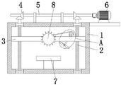
Fig. 1 is a schematic structural view of a cutting apparatus for steel according to the present invention;
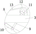
fig. 2 is a schematic structural view of a portion a of the cutting apparatus for steel according to the present invention;
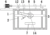
fig. 3 is the utility model provides a rear view structure schematic diagram of cutting equipment for steel.
In the figure: 1. a frame; 2. a threaded rod; 3. a transverse plate; 4. a first bevel gear; 5. rotating the rod; 6. a first motor; 7. cutting table; 8. a cutting blade; 9. a rotating shaft; 10. a fan blade; 11. a second bevel gear; 12. a belt pulley; 13. a belt; 14. a second motor.
Detailed Description
The technical solutions in the embodiments of the present invention will be described clearly and completely with reference to the accompanying drawings in the embodiments of the present invention, and it is obvious that the described embodiments are only some embodiments of the present invention, not all embodiments.
Referring to fig. 1-3, a cutting device for steel comprises a frame 1, two threaded rods 2 are rotatably mounted inside the frame 1, the outer sides of the two threaded rods 2 are in threaded connection with a same transverse plate 3, the outer side of the transverse plate 3 is slidably connected with the inner side of the frame 1, a cutting blade 8 is rotatably mounted on the front side of the transverse plate 3, a rotating shaft 9 is rotatably mounted inside the transverse plate 3, fan blades 10 are fixedly mounted at the bottom end of the rotating shaft 9, two second bevel gears 11 are rotatably mounted on one side of the top of the transverse plate 3, the two second bevel gears 11 are meshed with each other, the top end of the rotating shaft 9 extends to the top of the transverse plate 3 and is fixedly connected with the bottom of one second bevel gear 11 of the two second bevel gears 11, belt pulleys 12 are fixedly mounted on the rear sides of the other second bevel gear 11 and the, four first bevel gears 4 and a dwang 5 are installed to the top of frame 1 rotation, lie in two first bevel gears 4 intermeshing with one side in four first bevel gears 4, lie in the inboard of two first bevel gears 4 on the same horizontal axis and the outside fixed connection of dwang 5, the top of two threaded rods 2 all extends to the outside of frame 1 and with the bottom fixed connection of two other first bevel gears 4.
The utility model discloses in, the outside top fixed mounting of frame 1 has first motor 6, the output shaft of first motor 6 and the one end fixed connection of dwang 5, through the first motor 6 that sets up, drive first motor 6, thereby make dwang 5 rotate, thereby drive four first bevel gear 4 and rotate in step, make two threaded rod 2 rotate in step, thereby drive diaphragm 3 and obtain the function of vertical direction, thereby drive cutting blade 8 and flabellum 10 and obtain same function, thereby carry out cutting work.
The utility model discloses in, diaphragm 3's rear side fixed mounting has second motor 14, the output shaft of second motor 14 and the rear side fixed connection of a belt pulley 12 in two belt pulleys 12, second motor 14 through setting up, thereby drive second motor 14 makes two belt pulleys 12 rotate in step, thereby drive cutting blade 8 and two second bevel gear 11 rotate in step, second bevel gear 11's rotation drives pivot 9 and rotates, thereby drive flabellum 10 and rotate, finally make cutting blade 8 and flabellum 10 rotate in step, thereby make the waste material that can clear up the cutting in-process and produce among the cutting process.
The utility model discloses in, fixed mounting has the support column on the bottom inner wall of frame 1, and the top fixed mounting of support column has cutting bed 7, through cutting bed 7 that sets up, can put the steel that needs the cutting at cutting bed 7's top.
The utility model discloses in, the equal fixed mounting in top both sides of frame 1 has the gag lever post, and the outside of dwang 5 is rotated and is installed in the inboard of two gag lever posts, through the gag lever post that sets up to make the rotation of dwang 5 have certain scope to inject.
The utility model discloses in, frame 1's outside top fixed mounting has the backup pad, and thereby first motor 6 fixed mounting provides certain supporting role for first motor 6 through the backup pad that sets up at the top of backup pad.
The working principle of the cutting equipment is as follows: firstly, the steel to be cut is placed on top of the cutting table 7, then the second motor 14 is driven so as to rotate the two pulleys 12 synchronously, thereby driving the cutting blade 8 to rotate synchronously with the two second bevel gears 11, the rotation of the second bevel gears 11 drives the rotating shaft 9 to rotate, thereby driving the fan blade 10 to rotate, finally enabling the cutting blade 8 and the fan blade 10 to synchronously rotate, further cleaning the waste materials generated in the cutting process, then the first motor 6 is driven, so that the rotating rod 5 is rotated, and the four first bevel gears 4 are driven to synchronously rotate, so that the two threaded rods 2 synchronously rotate, thereby driving the transverse plate 3 to operate vertically, driving the cutting blade 8 and the fan blade 10 to operate in the same way, thereby performing a cutting work so that the steel placed on the surface of the cutting table 7 can be cut while the cutting blade 8 is moved downward.
Claims (6)
1. The utility model provides a cutting equipment for steel, which comprises a frame (1), a serial communication port, two threaded rods (2) are installed to the inside rotation of frame (1), the outside threaded connection of two threaded rods (2) has same diaphragm (3), the outside of diaphragm (3) and the inboard sliding connection of frame (1), cutting blade (8) are installed in the front side rotation of diaphragm (3), pivot (9) are installed in the inside rotation of diaphragm (3), the bottom fixed mounting of pivot (9) has flabellum (10), two second bevel gears (11) are installed in the top one side rotation of diaphragm (3), two second bevel gears (11) intermeshing, the top of pivot (9) extend to the top of diaphragm (3) and with the bottom fixed connection of one second bevel gear (11) in two second bevel gears (11), the equal fixed mounting in rear side of another second bevel gear (11) and the rear side of cutting blade (8) has belt pulley (12), the top of frame (1) is rotated and is installed four first bevel gears (4) and a dwang (5), lie in two first bevel gear (4) intermeshing with one side in four first bevel gears (4), the inboard of two first bevel gears (4) that lie in on the same horizontal axis and the outside fixed connection of dwang (5), the top of two threaded rods (2) all extends to the outside of frame (1) and with the bottom fixed connection of two other first bevel gears (4).
2. The steel cutting equipment according to claim 1, wherein a first motor (6) is fixedly installed at the top of the outer side of the frame (1), and an output shaft of the first motor (6) is fixedly connected with one end of the rotating rod (5).
3. The cutting equipment for the steel products as claimed in claim 1, characterized in that a second motor (14) is fixedly mounted at the rear side of the cross plate (3), and the output shaft of the second motor (14) is fixedly connected with the rear side of one pulley (12) of the two pulleys (12).
4. The cutting equipment for the steel according to claim 1, wherein a support column is fixedly installed on the inner wall of the bottom of the rack (1), and a cutting table (7) is fixedly installed on the top of the support column.
5. The steel cutting equipment according to claim 1, wherein the top of the frame (1) is fixedly provided with a limiting rod on both sides, and the outer side of the rotating rod (5) is rotatably arranged on the inner sides of the two limiting rods.
6. The steel cutting equipment according to claim 1, wherein a support plate is fixedly installed at the top of the outer side of the machine frame (1), and the first motor (6) is fixedly installed at the top of the support plate.
Priority Applications (1)
| Application Number | Priority Date | Filing Date | Title |
|---|---|---|---|
| CN202021573296.3U CN213104826U (en) | 2020-08-03 | 2020-08-03 | Cutting equipment for steel |
Applications Claiming Priority (1)
| Application Number | Priority Date | Filing Date | Title |
|---|---|---|---|
| CN202021573296.3U CN213104826U (en) | 2020-08-03 | 2020-08-03 | Cutting equipment for steel |
Publications (1)
| Publication Number | Publication Date |
|---|---|
| CN213104826U true CN213104826U (en) | 2021-05-04 |
Family
ID=75682693
Family Applications (1)
| Application Number | Title | Priority Date | Filing Date |
|---|---|---|---|
| CN202021573296.3U Expired - Fee Related CN213104826U (en) | 2020-08-03 | 2020-08-03 | Cutting equipment for steel |
Country Status (1)
| Country | Link |
|---|---|
| CN (1) | CN213104826U (en) |
-
2020
- 2020-08-03 CN CN202021573296.3U patent/CN213104826U/en not_active Expired - Fee Related
Similar Documents
| Publication | Publication Date | Title |
|---|---|---|
| CN213440154U (en) | Automatic furniture cutting and polishing integrated device | |
| CN213104826U (en) | Cutting equipment for steel | |
| CN211438418U (en) | Automatic wire-electrode cutting processingequipment of hardware | |
| CN218658427U (en) | Edge grinding processing equipment for bulletproof glass substrate | |
| CN214979357U (en) | Perforating device is used in handicraft processing | |
| CN110682347A (en) | Cutting device for plastic products | |
| CN211708163U (en) | Combined punching and shearing machine for production of transformer clamping piece | |
| CN218700268U (en) | Circulating slewing mechanism for stone machining | |
| CN214925215U (en) | Environment-friendly wood cutting device for furniture processing | |
| CN219705330U (en) | Longitudinal slicer | |
| CN221364986U (en) | Edge cutting mechanism for producing endurance plate | |
| CN220463225U (en) | Wallboard grinding power mechanism | |
| CN217858574U (en) | Steel bar cutting device for constructional engineering | |
| CN214560212U (en) | High vehicle air conditioner rotor apparatus for producing of stability | |
| CN217802154U (en) | Clamping furniture processing saw bench | |
| CN216300629U (en) | Automatic dust-cleaning engraving machine | |
| CN214652323U (en) | Automatic packaging device for bamboo fiber towels | |
| CN213794555U (en) | Laboratory ventilation cabinet panel cutting device | |
| CN221132365U (en) | Raw material processing equipment | |
| CN220699009U (en) | Horizontal high-efficient numerical control processing unit | |
| CN215152365U (en) | Cutting device is used in plastic bag production | |
| CN218138610U (en) | A cutting device for plank | |
| CN221641103U (en) | Vibrating knife cutting machine easy to adjust | |
| CN213358089U (en) | Cloth shearing mechanism is used in gauze mask production | |
| CN213136025U (en) | CNC turnning and milling comprehensive machining center machine |
Legal Events
| Date | Code | Title | Description |
|---|---|---|---|
| GR01 | Patent grant | ||
| GR01 | Patent grant | ||
| CF01 | Termination of patent right due to non-payment of annual fee | ||
| CF01 | Termination of patent right due to non-payment of annual fee |
Granted publication date: 20210504 Termination date: 20210803 |