CN213084543U - Steel pipe conveyer - Google Patents
Steel pipe conveyer Download PDFInfo
- Publication number
- CN213084543U CN213084543U CN202021766471.0U CN202021766471U CN213084543U CN 213084543 U CN213084543 U CN 213084543U CN 202021766471 U CN202021766471 U CN 202021766471U CN 213084543 U CN213084543 U CN 213084543U
- Authority
- CN
- China
- Prior art keywords
- steel pipe
- wheel set
- conveying
- conveying support
- splayed
- Prior art date
- Legal status (The legal status is an assumption and is not a legal conclusion. Google has not performed a legal analysis and makes no representation as to the accuracy of the status listed.)
- Active
Links
Images


Abstract
The utility model discloses a steel pipe conveying device, wherein a front wheel set and a rear wheel set are arranged at the bottom of a conveying bracket to be convenient to move, meanwhile, the front wheel set and the rear wheel set at the front end and the rear end of the transmission bracket can be respectively lifted and lowered independently through the hydraulic cylinder, so can make things convenient for the material loading or unload, when unloading, make one end descend extreme position under the effect of pneumatic cylinder, the other end rises under the effect of another group of pneumatic cylinder, whole conveying support slope, the steel pipe can utilize self gravity landing, in this while, still can make the steel pipe unload fast toward the reverse promotion of discharge opening with steel pipe conveyer, compare prior art more laborsaving, the efficiency is higher, the oblique roller is rotatable to be favorable to steel pipe material loading or to unload, the protection transmission band can rotate and rotate along with the oblique roller of multiunit inverted splayed roller group, the protection transmission band can protect the steel pipe to avoid receiving the damage that the collision of hard thing on the conveying support or friction lead to.
Description
Technical Field
The utility model relates to a steel pipe production and processing technology field especially relates to a steel pipe conveyer.
Background
The steel pipe usage is very extensive, has become the indispensable product of human production life, and in actual production, often need transport the steel pipe and shift because the factory space is limited, the steel pipe conveyer among the prior art all has an arcwall face usually, then manual handling and unloading, not only workman intensity of labour is big but also work efficiency is low.
Therefore, in order to solve the problems in the prior art, it is important to provide a steel pipe transportation technology that reduces the labor intensity of workers and improves the work efficiency.
Disclosure of Invention
An object of the utility model is to avoid the weak point among the prior art and provide a reduce workman intensity of labour and improve work efficiency's steel pipe conveyer.
The purpose of the utility model is realized through the following technical scheme:
the steel pipe conveying device comprises a conveying support, a front wheel set, a rear wheel set and a protective conveying belt, wherein the front wheel set and the rear wheel set are arranged at the bottom of the conveying support, the front wheel set and the rear wheel set respectively comprise two wheels, a connecting rod and a hydraulic cylinder, the two wheels are respectively and rotatably arranged on the connecting rod, one end of the hydraulic cylinder is fixedly connected to the connecting rod, the other end of the hydraulic cylinder is fixedly connected to the bottom of the conveying support, the hydraulic cylinder can drive the conveying support to ascend or descend, the hydraulic cylinder is connected with a hydraulic pump through a pipeline, and the hydraulic pump;
side fences are arranged on two sides of the conveying support, a plurality of cross rods are arranged between the side fences on the two sides, each cross rod is provided with a group of inverted splayed roller sets, each group of inverted splayed roller sets consists of two inclined rollers which are obliquely arranged, and the two inclined rollers are oppositely arranged in an inverted splayed manner;
the protection transmission band cover is in the upper portion of conveying support and around passing through multiunit inverted splayed roller set.
Preferably, two sides of the protection conveying belt are respectively provided with a limiting guard rail, and the limiting guard rails are fixed on the conveying support.
Preferably, the limiting protective guard is further provided with limiting pieces, and the lower parts of the limiting pieces are pressed on two side edges of the protective conveying belt.
Preferably, the limiting sheet is a rubber sheet.
Preferably, the inverted splayed roller set further comprises two supporting fork members and a splayed supporting member, the two supporting fork members are respectively fixed on the side rails on the two sides, the splayed supporting member is fixed on the cross rod, the supporting fork members are higher than the splayed supporting member, one end of the inclined roller is rotatably mounted on the supporting fork members, and the other end of the inclined roller is rotatably mounted on the splayed supporting member.
Preferably, the conveying bracket is also provided with a plurality of tension auxiliary rollers, and the plurality of tension auxiliary rollers are positioned below the cross bar and support the lower part of the protective conveying belt.
Preferably, the side rail is also provided with a handle.
The utility model has the advantages that:
(1) preceding wheelset and back wheelset are installed in the bottom of conveying support and are convenient for remove, and simultaneously, the preceding wheelset and the back wheelset at both ends can go up and down alone through the pneumatic cylinder respectively around the conveying support, so can make things convenient for the material loading or unload, when unloading, make one end descend extreme position under the effect of pneumatic cylinder, the other end rises under the effect of another group of pneumatic cylinder, the slope of whole conveying support, the steel pipe can utilize self gravity landing, in this moment, still can make the steel pipe unload fast toward the reverse promotion of discharge opening with steel pipe conveyer, compare prior art more laborsavingly, high efficiency.
(2) Side fences are arranged on two sides of the conveying support, a plurality of cross rods are arranged between the side fences on the two sides, each cross rod is provided with a group of inverted splayed roller sets, each group of inverted splayed roller sets consists of two inclined rollers which are obliquely arranged, and the two inclined rollers are oppositely arranged in an inverted splayed manner; so set up, can concentrate on the middle part of conveying support with the steel pipe and prevent to drop, simultaneously, the oblique roller is rotatable to be favorable to the steel pipe material loading or unload.
(3) The utility model discloses still be equipped with the protection transmission band, the protection transmission band cover is on the upper portion of conveying support and around the splayed roller set of multiunit, and the protection transmission band can rotate and rotate along with the skewed roller of the splayed roller set of multiunit, and the protection transmission band can protect the steel pipe to avoid receiving the damage that the collision of the hard thing on the conveying support or friction lead to.
Drawings
The present invention is further explained by using the attached drawings, but the content in the attached drawings does not constitute any limitation to the present invention.
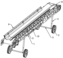
Fig. 1 is a schematic structural diagram of an embodiment of the present invention.
Fig. 2 is another angle structure diagram of an embodiment of the present invention.
Fig. 3 is a schematic structural view of the present invention with the protective transmission belt removed.
Fig. 4 is a schematic view of a state when one end of the present invention is raised.
Fig. 5 is a schematic view of the structure of fig. 4 with the guard belt removed.
Fig. 1 to 5 include:
the device comprises a conveying support 1, a side rail 1-1, a cross bar 1-2, wheels 2, a connecting rod 3, a hydraulic cylinder 4, an inclined roller 5, a supporting fork 6, a splayed supporting piece 7, a protective conveying belt 8, a limiting protective guard 9, a limiting sheet 9-1 and a tension auxiliary roller 10.
Detailed Description
The present invention will be further illustrated with reference to the following examples.
Example 1
As shown in fig. 1 to 5, the steel pipe transportation device of this embodiment includes a conveying support 1, a front wheel set, a rear wheel set and a protective transmission belt 8, the front wheel set and the rear wheel set are installed at the bottom of the conveying support 1, the front wheel set and the rear wheel set both include two wheels, a connecting rod 3 and a hydraulic cylinder 4, the two wheels 2 are respectively and rotatably installed on the connecting rod 3, one end of the hydraulic cylinder 4 is fixedly connected to the connecting rod 3, the other end of the hydraulic cylinder 4 is fixedly connected to the bottom of the conveying support 1, the hydraulic cylinder 4 can drive the conveying support 1 to ascend or descend, the hydraulic cylinder 4 is connected to a hydraulic pump (not shown) through a pipeline. In this embodiment, the hydraulic cylinder 4 is used as both a support leg and a lifting driving device, and the steel pipe transporting device can be conveniently loaded or unloaded by controlling the lifting of the hydraulic cylinder 4, so that the labor is saved, and the working efficiency is high.
In this embodiment, the two sides of the conveying bracket 1 are both provided with side rails 1-1, the side rails 1-1 can be further provided with handles as required to facilitate a worker to hold the pushing device, and the worker can also directly grip the pushing device of the side rails 1-1 to move. A plurality of cross rods 1-2 are arranged between the side fences 1-1 at two sides, each cross rod 1-2 is provided with a group of inverted splayed roller sets, each group of inverted splayed roller sets is composed of two inclined rollers 5 which are obliquely arranged, and the two inclined rollers 5 are oppositely arranged in an inverted splayed manner, so that the steel pipes can be concentrated in the middle part to avoid falling or scattering. The inverted splayed roller set further comprises two supporting fork members 6 and a splayed supporting member 7, the two supporting fork members 6 are respectively fixed on the side rails 1-1 on the two sides, the splayed supporting member 7 is fixed on the cross rod 1-2, the supporting fork members 6 are higher than the splayed supporting member 7, one end of the inclined roller 5 is rotatably installed on the supporting fork members 6, and the other end of the inclined roller is rotatably installed on the splayed supporting member 7. The inverted splayed roller set further comprises two supporting fork parts 6 and a splayed supporting part 7, the two supporting fork parts 6 are respectively fixed on the side rails 1-1 on the two sides, the splayed supporting part 7 is fixed on the cross rod 1-2, the supporting fork parts 6 are higher than the splayed supporting part 7, one end of the inclined roller 5 is rotatably installed on the supporting fork parts 6, and the other end of the inclined roller is rotatably installed on the splayed supporting part 7.
In order to protect the steel pipe, this embodiment is still provided with protection transmission band 8. This protection transmission band 8 cover is on the upper portion of conveying support 1 and around the splayed roller set of multiunit, and protection transmission band 8 is made for rubber, and is relatively soft, can protect the steel pipe to avoid scraping flower or damage. In order to better transport the steel pipes, the two sides of the protective conveying belt 8 are respectively provided with a limiting guard rail 9, the limiting guard rails 9 are fixed on the conveying support 1, the limiting guard rails 9 are further provided with limiting pieces 9-1, the lower parts of the limiting pieces 9-1 are pressed on the two side edges of the protective conveying belt 8 to prevent the side edges of the protective conveying belt 8 from tilting, and the limiting pieces can be better butted to jointly receive the steel pipes. In this embodiment, the limiting sheet 9-1 is a rubber sheet, and the limiting sheet 9-1 used for limiting needs a certain hardness, so the thickness of the limiting sheet 9-1 is thicker than that of the protective transmission belt 8.
Example 2
The main technical solution of this embodiment is substantially the same as that of embodiment 1, and the features that are not explained in this embodiment adopt the explanations in embodiment 1, and are not described herein again. In the embodiment, on the basis of the embodiment 1, a plurality of tension auxiliary rollers 10 are further installed on the conveying bracket 1, and the plurality of tension auxiliary rollers 10 are positioned below the cross bar 1-2 to support the lower part of the protective conveying belt 8.
Finally, it should be noted that the above embodiments are only used for illustrating the technical solutions of the present invention and do not limit the protection scope of the claims. It will be understood by those skilled in the art that various modifications and substitutions can be made to the preferred embodiment without departing from the spirit and scope of the invention.
Claims (7)
1. Steel pipe conveyer, its characterized in that: the device comprises a conveying support, a front wheel set, a rear wheel set and a protective conveying belt, wherein the front wheel set and the rear wheel set are arranged at the bottom of the conveying support, the front wheel set and the rear wheel set respectively comprise two wheels, a connecting rod and a hydraulic cylinder, the two wheels are respectively and rotatably arranged on the connecting rod, one end of the hydraulic cylinder is fixedly connected to the connecting rod, the other end of the hydraulic cylinder is fixedly connected to the bottom of the conveying support, the hydraulic cylinder can drive the conveying support to ascend or descend, the hydraulic cylinder is connected with a hydraulic pump through a pipeline, and the;
the conveying device comprises a conveying support, a plurality of transverse rods, a plurality of inclined rollers and a plurality of transverse rods, wherein the conveying support is provided with side fences on two sides, a plurality of transverse rods are arranged between the side fences on the two sides, each transverse rod is provided with a group of inverted splayed roller sets, each group of inverted splayed roller sets consists of two inclined rollers which are obliquely arranged, and the two inclined rollers are oppositely arranged in an inverted splayed;
the protection transmission band cover is in the upper portion of conveying support and around passing through multiunit inverted splayed roller set.
2. The steel pipe transportation apparatus of claim 1, wherein: and two sides of the protection conveying belt are respectively provided with a limiting protective guard, and the limiting protective guard is fixed on the conveying support.
3. The steel pipe transportation apparatus of claim 2, wherein: the limiting protective guard is further provided with limiting pieces, and the lower parts of the limiting pieces are pressed on two side edges of the protective conveying belt.
4. The steel pipe transportation apparatus of claim 3, wherein: the limiting sheet is a rubber sheet.
5. The steel pipe transportation apparatus of claim 1, wherein: the inverted splayed roller set further comprises two supporting fork pieces and a splayed supporting piece, the two supporting fork pieces are respectively fixed on the side fences of the two sides, the splayed supporting piece is fixed on the cross rod, the supporting fork pieces are higher than the splayed supporting piece, one end of the inclined roller is rotatably installed on the supporting fork pieces, and the other end of the inclined roller is rotatably installed on the splayed supporting piece.
6. The steel pipe transportation apparatus of claim 1, wherein: the conveying support is further provided with a plurality of tension auxiliary rollers, and the tension auxiliary rollers are located below the cross rod and support the lower portion of the protection conveying belt.
7. The steel pipe transportation apparatus of claim 1, wherein: the side rail can also be provided with a handle.
Priority Applications (1)
| Application Number | Priority Date | Filing Date | Title |
|---|---|---|---|
| CN202021766471.0U CN213084543U (en) | 2020-08-21 | 2020-08-21 | Steel pipe conveyer |
Applications Claiming Priority (1)
| Application Number | Priority Date | Filing Date | Title |
|---|---|---|---|
| CN202021766471.0U CN213084543U (en) | 2020-08-21 | 2020-08-21 | Steel pipe conveyer |
Publications (1)
| Publication Number | Publication Date |
|---|---|
| CN213084543U true CN213084543U (en) | 2021-04-30 |
Family
ID=75631621
Family Applications (1)
| Application Number | Title | Priority Date | Filing Date |
|---|---|---|---|
| CN202021766471.0U Active CN213084543U (en) | 2020-08-21 | 2020-08-21 | Steel pipe conveyer |
Country Status (1)
| Country | Link |
|---|---|
| CN (1) | CN213084543U (en) |
Cited By (2)
| Publication number | Priority date | Publication date | Assignee | Title |
|---|---|---|---|---|
| CN113686565A (en) * | 2021-09-14 | 2021-11-23 | 淮安市产品质量监督综合检验中心 | Plastic garbage can hanging endurance testing machine and method |
| CN116140909A (en) * | 2023-04-21 | 2023-05-23 | 临沂市政集团有限公司 | Pipeline connecting device in municipal administration |
-
2020
- 2020-08-21 CN CN202021766471.0U patent/CN213084543U/en active Active
Cited By (2)
| Publication number | Priority date | Publication date | Assignee | Title |
|---|---|---|---|---|
| CN113686565A (en) * | 2021-09-14 | 2021-11-23 | 淮安市产品质量监督综合检验中心 | Plastic garbage can hanging endurance testing machine and method |
| CN116140909A (en) * | 2023-04-21 | 2023-05-23 | 临沂市政集团有限公司 | Pipeline connecting device in municipal administration |
Similar Documents
| Publication | Publication Date | Title |
|---|---|---|
| CN213084543U (en) | Steel pipe conveyer | |
| CN112777329A (en) | Reciprocating vertical conveyor | |
| CN106809632A (en) | The handling equipment of horizontal oxidation line | |
| CN207565646U (en) | A kind of cart convenient for handling goods | |
| CN206537898U (en) | The handling equipment of horizontal oxidation line | |
| CN205471464U (en) | Ceramic product hangs auto -control handling device of transfer chain | |
| CN214140699U (en) | Construction is with supplementary shedding mechanism | |
| CN214570422U (en) | Lifting conveying connection trolley | |
| CN212100819U (en) | Automatic transfer device convenient for unloading for logistics line | |
| CN211077311U (en) | High-precision hot shearing furnace for aluminum pipe production | |
| CN212711668U (en) | High-efficient glass handling device | |
| CN209754315U (en) | Material supporting device of laser cutting machine | |
| CN210038867U (en) | High-efficient storage logistics equipment | |
| CN210557717U (en) | Load transferring and blanking device | |
| CN113911768A (en) | Loading stacker | |
| JPS6019602A (en) | Transferring apparatus for handling object | |
| CN112027580A (en) | Building materials conveyer of material loading is convenient for with building materials production | |
| CN104925532A (en) | Small trolley type PVC (polyvinyl chloride) tube loading machine | |
| CN219314469U (en) | A conveyer for electronic sofa production | |
| CN213444614U (en) | Transfer conveying device for deformed steel hot rolling mill | |
| CN212981347U (en) | Linear feeding device for goods shelf | |
| CN201960334U (en) | Carrier roller replacing tool | |
| CN209871433U (en) | Log side-by-side conveying device | |
| CN220244399U (en) | Bottom supporting and conveying device for conveying logistics trolley | |
| CN220182186U (en) | Raw and other materials transportation is with transporting frock |
Legal Events
| Date | Code | Title | Description |
|---|---|---|---|
| GR01 | Patent grant | ||
| GR01 | Patent grant |