CN212978562U - Dust suction device of special paper slitting and stripping machine - Google Patents
Dust suction device of special paper slitting and stripping machine Download PDFInfo
- Publication number
- CN212978562U CN212978562U CN202021963519.7U CN202021963519U CN212978562U CN 212978562 U CN212978562 U CN 212978562U CN 202021963519 U CN202021963519 U CN 202021963519U CN 212978562 U CN212978562 U CN 212978562U
- Authority
- CN
- China
- Prior art keywords
- base film
- suction
- dust collection
- special paper
- collection box
- Prior art date
- Legal status (The legal status is an assumption and is not a legal conclusion. Google has not performed a legal analysis and makes no representation as to the accuracy of the status listed.)
- Active
Links
Images


Landscapes
- Cleaning In General (AREA)
Abstract
The application relates to a special paper cuts and peels off quick-witted dust extraction, including base film winding mechanism, its characterized in that: the base film winding mechanism is characterized in that a base film cleaning mechanism is arranged in front of the base film winding mechanism and comprises a suction mechanism, the suction mechanism comprises a dust collection box, a group of suction pipelines used for sucking the surface of the base film are arranged on the dust collection box, and a suction port is formed in the suction pipeline. This application is through setting up suction mechanism, with the adnexed debris suction of base film surface away to the realization is to the clearance of whole base film.
Description
Technical Field
The application relates to the technical field of special paper, in particular to a dust suction device of a special paper slitting and stripping machine.
Background
At present, a plurality of special papers are required to be used in the production and processing processes of cigarettes, and the transfer paper is one of the special papers. The production method of the high-brightness tipping paper widely applied to the tobacco packaging industry at present comprises the steps of carrying out composite transfer on a BOPP or PET film and base paper, namely coating transfer coating on the BOPP or PET film through a mesh wire roller, drying the BOPP or PET film through an oven, completing coating, then compounding the BOPP or PET film with paper, and stripping the BOPP or PET film after drying and curing to obtain the high-brightness tipping paper. Most of stripping machines on the market at present do not have the function of double rolling of paper and films, so that the stripping machines need to be modified
In order to solve the problems, the chinese patent with publication number CN207467789U discloses a peeling, slitting and winding device for transfer paper, which comprises an unwinding device, a peeling device, a base film winding device, a paper slitting device and a product winding device, thereby realizing the function of double winding of paper and film on the same device.
The scheme still has the following problems that the base film cannot be reused due to the unclean state of the base film after the base film is rolled, and a large amount of raw materials are wasted.
Disclosure of Invention
The utility model provides a special paper cuts and peels off quick-witted dust extraction cuts, through setting up suction mechanism, takes away the adnexed debris suction in base film surface to the realization is to the clearance of whole base film.
The above application purpose of the present application is achieved by the following technical solutions:
the utility model provides a special paper cuts and peels off quick-witted dust extraction, includes base film winding mechanism, its characterized in that: the base film winding mechanism is characterized in that a base film cleaning mechanism is arranged in front of the base film winding mechanism and comprises a suction mechanism, the suction mechanism comprises a dust collection box, a group of suction pipelines used for sucking the surface of the base film are arranged on the dust collection box, and a suction port is formed in the suction pipeline.
Through adopting above-mentioned technical scheme, suction mechanism in the base film clearance mechanism can aspirate the base film surface, and the base film can be followed just to passing through between a set of suction pipe of setting, and suction pipe can follow the suction mouth position and aspirate the base film surface when the base film passes through, carries out the suction clearance to debris on the base film.
Preferably, a plurality of suction heads are arranged on the suction pipeline.
Through adopting above-mentioned technical scheme, the distance between suction opening and the base film can be taut in the setting of suction head to make the suction wind power degree that gets into from the suction opening gather more with the base film surface, thereby strengthened the suction dynamics of suction pipeline to the base film.
Preferably, a suction brush is arranged at the opening of the suction head.
Through adopting above-mentioned technical scheme, the setting up of suction brush can make the suction head clean the attachment on base film surface when the suction to make the base film that is difficult for coming off from the base film surface sweep down from the base film surface, thereby made things convenient for the suction of suction pipeline to these debris that are difficult for coming off.
Preferably, the inner wall of the dust collection box is attached with a dense gauze.
Through adopting above-mentioned technical scheme, the setting of intensive gauze can prevent that the dust that gets into in the dust collecting box from escaping the dust collecting box from dust collecting box internal gap department.
Preferably, a plurality of layers of filter screens are arranged in the dust collection box.
Through adopting above-mentioned technical scheme, the setting of filter screen can carry out the multilayer to dust or debris that get into in the dust collection box and filter many times to guarantee that dust and debris can be adsorbed on the filter screen, when the staff cleared up the dust collection box, the dust major part can be attached to on the filter screen, and the staff only need mainly change the clearance to the filter screen this moment, has reduced that the staff is long when the cleaning work of wasing incasement portion is required.
Preferably, a sealing door is arranged on the dust collection box corresponding to each filter screen.
Through adopting above-mentioned technical scheme, the setting of sealing door can make things convenient for the staff to change the filter screen, and the dust in the dust collecting tank can be avoided from the dust collecting tank effusion in the setting of sealing door simultaneously.
Preferably, a sealing gasket is arranged between the sealing door and the dust collection box.
Through adopting above-mentioned technical scheme, sealed setting up of sealed pad can be further the assurance sealing door and dust collection box between sealed.
Preferably, a lifting handle is arranged on the sealing door.
Through adopting above-mentioned technical scheme, carry the handle and made things convenient for opening of staff with sealing door.
To sum up, the beneficial technical effect of this application does:
through setting up suction mechanism, take out the adnexed debris suction of base film surface away to the realization is to the clearance of whole base film.
Drawings
Fig. 1 is a schematic view of the overall structure of the present application.
Fig. 2 is a schematic view of the structure of the trimming mechanism of the present application.
FIG. 3 is a schematic view of another perspective of the trimming mechanism of the present application, which is intended to show the receiving pipe structure.
Figure 4 is a schematic view of a slitting mechanism of the present application,
fig. 5 is a schematic view of the internal structure of the base film cleaning mechanism of the present application.
Fig. 6 is a partially enlarged schematic view of a portion a in fig. 5.
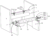
Fig. 7 is a schematic view of the structure of the suction mechanism of the present application.
Fig. 8 is a schematic view of the suction duct structure of the present application, intended to show the structure of the suction head.
Figure 9 is a schematic view of the internal structure of the dust bin of the present application.
Fig. 10 is a partially enlarged schematic view of a portion B in fig. 7.
Reference numerals: 1. a body; 2. an unwinding mechanism; 21. an air expansion shaft; 22. an unwinding cavity; 23. a bearing shaft sleeve; 24. a bearing groove; 25. a limiting mechanism; 251. an adjusting seat; 252. adjusting the screw rod; 253. unreeling a pressing plate; 254. a limiting ring; 256. a ring groove; 3. a trimming mechanism; 31. a cutter shaft; 32. a trimming knife; 33. a sliding plate; 34. a graduated scale; 35. hooping; 351. a fixing hoop; 352. a rotating hoop; 36. a material receiving pipeline; 37. a material receiving box; 371. cleaning the door; 4. a peeling mechanism; 5. a transfer paper winding mechanism; 6. a base film winding mechanism; 7. a base film cleaning mechanism; 71. a base film cleaning box; 711. a cleaning chamber; 712. a draining cavity; 7121. a suction roll; 7122. a squeeze roll; 7123. a water guide plate; 7124. a water outlet; 713. a lower pressing plate; 714. pressing down the air cylinder; 715. a protective roller; 716. cleaning the roller; 717. a buffer seat; 7171. a base body; 7172. a buffer chamber; 7173. a buffer hole; 7174. a buffer rod; 7175. a buffer spring; 7176. a guide plate; 7177. a guide hole; 7178. a buffer ring; 7179. a flexible rubber pad; 72. a suction mechanism; 721. a dust collection box; 722. a dust collection fan; 723. a suction duct; 724. a suction head; 725. a suction brush; 726. dense gauze; 727. filtering the gauze; 728. a chute; 729. a sealing door; 7291. a gasket; 7292. lifting the handle; 8. a slitting mechanism; 81. a cutting frame; 82. a slitting roller; 83. a slide bar; 84. an adjusting plate; 85. a slitting knife; 86. moving the screw; 87. the motor is regulated.
Detailed Description
The present application is described in further detail below with reference to the attached drawings.
Referring to fig. 1, for this application discloses a special paper cuts and peels off quick-witted dust extraction, including organism 1, have set gradually unwinding mechanism 2, trimming mechanism 3, peeling mechanism 4, transfer paper winding mechanism 5 and base film winding mechanism 6 on the organism 1, in order to realize the use of retrieving many times to the base film simultaneously, be provided with base film wiper mechanism 7 before base film winding mechanism 6.
Referring to fig. 1 and 2, the unwinding mechanism 2 includes an inflatable shaft 21 disposed at one end of the body 1, an unwinding chamber 22 is disposed on the body 1 corresponding to the inflatable shaft 21, the inflatable shaft 21 straddles over the unwinding chamber 22, and in order to prevent the two ends of the inflatable shaft 21 from being worn greatly on the wall of the unwinding chamber 22, bearing sleeves 23 are disposed at the two ends of the inflatable shaft 21, splines are disposed in the bearing sleeves 23, key slots are disposed at the two ends of the inflatable shaft 21 in cooperation with the splines, a bearing slot 24 is disposed at the top end of the wall of the unwinding chamber 22 in cooperation with the bearing sleeves 23, the bearing slot 24 is an arc-shaped slot conforming to the arc surface of the side surface of the bearing sleeve 23, and considering that the bearing sleeve 23 needs to be limited in the bearing slot 24, a limiting mechanism 25 for limiting the position of the bearing sleeve 23 is disposed on the bearing slot 24, the limiting mechanism 25 includes an adjusting seat 251 fixedly connected with the wall of the unwinding chamber 22, an adjusting screw 252 is arranged on the adjusting seat 251, and an unwinding pressing plate 253 is arranged on one end, facing the bearing sleeve, of the adjusting screw 252. Further, in order to prevent the bearing shaft seat from being separated from the bearing groove 24 along the axial direction, a limiting ring 254 is arranged on the bearing sleeve, and an annular groove 256 is arranged in the bearing groove 24 in cooperation with the limiting ring 254, when the bearing shaft sleeve 23 is placed in the bearing groove 24, the limiting ring 254 is inserted into the annular groove 256, so that the bearing shaft sleeve 23 is limited. And a traction roller is arranged between the unreeling mechanism 2 and the trimming mechanism 3 on the machine body 1.
Referring to fig. 2 and 3, in the production process of the transfer paper, the transfer coating on the base film needs to be coated first, and then the base film and the transfer paper are compounded to transfer the transfer coating on the base film to the transfer paper, but in the compounding process, the adhesion phenomenon often occurs at the edges of the base film and the transfer paper, and the adhesion part of the base film and the transfer paper affects the subsequent base film peeling process, so that the edge of the base film adhered to the transfer paper needs to be cut off first by the trimming mechanism 3 and then the base film is peeled. The trimming mechanism 3 comprises a trimming roller, a trimming knife shaft 31 is arranged on the trimming roller, a trimming knife 32 is arranged on the trimming knife shaft 31, and the position of the trimming knife 32 needs to be adjusted in consideration of the possibility that the width of the adhered part is different, so that a sliding plate 33 is arranged on the trimming knife 32, the sliding plate 33 is connected with the trimming knife shaft 31 in a sliding manner, and a graduated scale 34 is arranged on the trimming knife shaft 31 corresponding to the position of the sliding plate 33. The sliding plate 33 is provided with a positioning hoop 35 for fixing the position of the edge cutting knife 32, a positioning fixing hoop 351 and a rotating hoop 352, wherein the fixing hoop 351 is hinged with one end of the rotating hoop 352, and the other end of the fixing hoop is fixedly connected with the other end of the rotating hoop through a fixing bolt. Simultaneously corresponding side cut sword 32 position slope and being provided with receipts material pipeline 36, and receive the setting of material pipe open end towards cutter direction, just the bottom orientation of receiving the material pipe is kept away from cutter one side and is set up, and receives the opening of material pipeline 36 and personally submit horizontal ellipse and describe the setting, receives the other end of material pipeline 36 and is provided with receipts workbin 37, is provided with clearance door 371 on the receipts workbin 37.
Referring to fig. 1 and 4, after the edge portion of the base film adhered to the transfer paper is cut off, the transfer paper covered with the base film can be peeled off in the peeling mechanism 4, after the peeling mechanism 4 peels off, the transfer paper needs to enter the transfer paper winding mechanism 5 to wind the transfer paper, at this time, the transfer coating on the base film is already attached to the surface of the transfer paper, but considering that the transfer paper needs to be cut into different specifications according to the requirements of customers, the cutting mechanism 8 needs to be arranged between the transfer paper winding mechanism 5 and the peeling mechanism 4 during the use process, the cutting mechanism 8 comprises a cutting frame 81 arranged on the machine body 1, a cutting roller 82 is arranged on the machine body 1 corresponding to the cutting frame 81, a sliding rod 83 is arranged on the cutting frame 81 parallel to the cutting roller 82, a regulating plate 84 is arranged on the sliding rod 83, a cutting knife 85 is arranged on the regulating plate 84 towards one side of the cutting roller 82, and two moving screws 86 with different feeding directions are arranged in parallel with the sliding rod 83, the moving screws 86 are in threaded connection with the adjusting plates 84, any adjacent adjusting plate 84 is in threaded connection with different moving screws 86, and adjusting motors 87 are arranged at the end parts of the two moving rod screws.
Referring to fig. 1 and 5, further in order to realize the reuse to the base film, need wash the base film before the base film carries out the rolling axle, so be provided with base film wiper mechanism 7 before base film rolling mechanism 6, base film wiper mechanism 7 includes base film washing case 71, base film washing case 71 includes feed inlet and discharge gate, and base film washing case 71 is provided with the washing chamber 711 and the waterlogging caused by excessive rainfall chamber 712 of intercommunication, washing chamber 711 sets up with the feed inlet intercommunication, waterlogging caused by excessive rainfall chamber 712 sets up with the discharge gate intercommunication, be provided with the charge door that is used for adding the washing liquid on the washing chamber 711 roof.
Referring to fig. 5 and 6, in order to ensure the soaking time and the soaking area of the base film in the cleaning solution during use, a soaking assembly is arranged in the cleaning chamber 711, the soaking assembly comprises a lower pressing plate 713 arranged on the top wall, a downward driving member for driving the lower pressing plate 713 is arranged on the outer top wall of the base film cleaning tank 71, the downward driving member is a downward cylinder 714, the output end of the downward cylinder 714 penetrates through the top wall of the cleaning chamber 711 to be fixedly connected with the lower pressing plate 713, meanwhile, in order to prevent the base film from being cut by the lower pressing plate 713, a plurality of protective rollers 715 are arranged side by side on one side of the lower pressing plate 713, which is far away from the downward cylinder 714, and the rotating direction of the protective rollers 715 is the same as the conveying direction of the base film. Simultaneously for further wash the base film, be provided with cleaning roller 716 at the bottom wall corresponding holding down plate 713 position in washing chamber 711, cleaning roller 716 surface is provided with the washing brush, and cleaning roller 716 both ends are rotated and are connected with buffer seat 717, buffer seat 717 and washing chamber 711 lateral wall fixed connection. The buffer seat 717 comprises a seat body 7171 fixedly connected with the side wall of the cleaning cavity 711, a semi-open buffer cavity 7172 with a C-shaped cross section is arranged on the seat body 7171, a buffer hole 7173 is arranged on the top wall of the buffer cavity 7172, a buffer rod 7174 is arranged in the buffer hole 7173 in a penetrating way, a connecting seat which is rotatably connected with the cleaning roller 716 is arranged above the buffer rod 7174, a buffer spring 7175 is sleeved outside the part of the buffer rod 7174 which is positioned in the buffer cavity 7172, a guide plate 7176 is arranged on the side wall of the buffer cavity 7172 in the direction vertical to the guide rod, a guide hole 7177 is arranged on the guide plate 7176 at the position opposite to the buffer hole 7173, the guide rod passes through the guide hole 7177 and the buffer hole 7173, a buffer spring 7175 sleeved outside the guide rod is arranged between the guide plate 7176 and the top wall of the buffer cavity 7172, meanwhile, a buffer ring 7178 is provided on the guide rod at a position close to the buffer hole 7173, and the buffer ring 7178 is provided in contact with the top wall of the buffer spring 7175. In order to prevent the bumper bar 7174 from colliding with the bottom wall of the guide hole 7177, flexible rubber pads 7179 are provided on both the inner bottom surface of the bumper chamber 7172 and the bottom surface of the guide bar.
Referring to fig. 5, a dewatering mechanism is further disposed in the draining cavity 712, the dewatering mechanism includes two water-absorbing rollers 7121 disposed opposite to each other in the horizontal direction, each water-absorbing roller 7121 is provided with a water-absorbing member as described above, in this embodiment, the water-absorbing member is a water-absorbing sponge, a squeezing roller 7122 abutted to the water-absorbing roller 7121 is disposed on a side of each water-absorbing roller 7121 away from the base film, water in the water-absorbing sponge can be squeezed out of the water-absorbing sponge by squeezing between the squeezing roller 7122 and the water-absorbing roller 7121, an axis of the water-absorbing roller 7121 is disposed parallel to an axis of the squeezing roller, a water guide plate 7123 is disposed below the squeezing roller 7122, the water guide plate 7123 can guide the water squeezed out of the water-absorbing sponge to the bottom wall of the draining cavity 712, and prevent the water flowing out of the water. Be provided with multiunit dewatering mechanism in vertical direction, can carry out the dewatering to the base film many times, strengthen the dewatering effect. And a drainage outlet 7124 is arranged at the position of the base film cleaning box 71 corresponding to the drainage cavity 712.
Referring to fig. 7 and 8, in order to further clean the surface of the base film, a suction mechanism 72 for sucking sundries adhered to the surface of the base film is arranged at a discharge port of a base film cleaning box 71, the suction mechanism 72 comprises a dust collection box 721, a dust suction fan 722 is externally connected to the dust collection box 721, two suction pipelines 723 are arranged on the dust collection box 721, the two suction pipelines 723 are symmetrically arranged by taking the base film as a symmetrical plane, a plurality of suction heads 724 are arranged on the suction pipelines 723, the open ends of the suction heads 724 are square, and the open ends of the suction heads 724 arranged side by side are abutted with each other. The suction head 724 is provided with a suction brush 725 for sweeping down foreign matters attached to the surface of the base film.
Referring to fig. 8 and 9, in order to prevent dust from entering the dust suction fan 722 or coming out of the dust box 721 from other gaps of the dust box 721, a dense screen 726 is provided on an inner wall surface of the dust box 721. Meanwhile, a plurality of layers of filter gauzes 727 are sequentially arranged in the dust collection box 721 from the connection part of the suction pipeline 723 and the dust collection box 721 to the connection part of the dust collection fan 722 and the dust collection box 721, 3 layers of long gauzes are arranged in the embodiment, the mesh density of the filter gauzes 727 is gradually increased along the direction from the suction pipeline 723 to the dust collection fan 722, a chute 728 into which the filter gauze 727 is inserted is arranged in the dust collection box 721 in a matching way, a sealing door 729 is arranged on the dust collection box 721 corresponding to each filter gauze 727, referring to fig. 10, a sealing gasket 7291 is arranged between the sealing door 729 and the dust collection box 721, a lifting handle 7292 is arranged on the sealing door 729, and the base film can enter the base film winding mechanism 6 to be wound up into a roll shape after being sucked by the suction mechanism 72, so as to be convenient for next use.
The implementation principle of the embodiment is as follows: when the transfer paper coated with the base film is cut and peeled off, firstly, the inflatable shaft 21 is inserted into a reel-shaped transfer paper cylinder, the bearing shaft sleeve 23 is sleeved at two ends of the inflatable shaft 21, the inflatable shaft 21 is controlled to work, the inflatable shaft 21 can tightly push the transfer paper cylinder from the inside, then the inflatable shaft 21 and the transfer paper are lifted up to be prevented from being in the unwinding cavity 22, the bearing shaft sleeve 23 enters the bearing groove 24, the limiting ring 254 is inserted into the ring groove 256, then the traction roller is started, the transfer paper coated with the base film enters the edge cutting mechanism 3, the edge cutting knife 32 cuts off the adhesion part of the edge of the transfer paper, the cut waste materials enter the material receiving pipeline 36 and enter the material receiving box 37 along the material receiving pipeline 36; the base film can enter the peeling mechanism 4 to be peeled off, after the transfer paper coated with the base film is peeled off in the peeling mechanism 4, the base film and the transfer paper are separated from the peeling mechanism 4, the transfer paper enters the slitting mechanism 8, a worker controls the adjusting screw 252 to drive the slitting knife 85 to move according to customer requirements, when the transfer paper moves between the slitting roller 82 and the slitting knife 85, the transfer paper can be cut into a required specification, then the transfer paper can enter the transfer paper winding mechanism 5, and under the driving of the winding power mechanism, the winding shaft can wind the transfer paper.
The base film enters the base film cleaning box 71 in the base film cleaning mechanism 7 after leaving from the peeling mechanism 4, enters the cleaning cavity 711 from the feed inlet of the base film cleaning box 71, and in the cleaning cavity 711, the pressing plate 713 presses downwards, the base film is immersed in the cleaning agent in the cleaning cavity 711 at the moment, the pressing plate 713 presses downwards to be in contact with the cleaning roller 716, and the brush base film is cleaned under the extrusion of the cleaning roller 716 and the protection roller 715. After the base film is cleaned in the cleaning chamber 711, the base film enters the draining chamber 712, water on the base film in the draining chamber 712 is absorbed by the water absorbing sponge on the water absorbing roller 7121 to remove water from the base film, and then the base film passes between the two opposite suction pipes 723 of the suction mechanism 72, and fine impurities still attached to the surface of the base film are sucked away from the base film by the suction brushes 725 and the suction head 724. The base film can enter the base film winding mechanism 6 after being sucked by the suction mechanism 72, and the base film is wound on the winding shaft of the base film winding mechanism 6 under the action of the winding power mechanism of the base film winding mechanism 6.
The embodiments of the present invention are preferred embodiments of the present application, and the scope of protection of the present application is not limited by the embodiments, so: all equivalent changes made according to the structure, shape and principle of the present application shall be covered by the protection scope of the present application.
Claims (8)
1. The utility model provides a special paper cuts and peels off quick-witted dust extraction, includes base film winding mechanism (6), its characterized in that: the base film winding mechanism is characterized in that a base film cleaning mechanism is arranged in front of the base film winding mechanism (6), the base film cleaning mechanism comprises a suction mechanism (72), the suction mechanism (72) comprises a dust collection box (721), a group of suction pipelines (723) used for sucking the surface of the base film are arranged on the dust collection box (721) in a facing mode, and suction ports are formed in the suction pipelines (723).
2. The special paper slitting and peeling machine dust collection device of claim 1, characterized in that: a plurality of suction heads (724) are arranged on the suction pipeline (723).
3. The special paper slitting and peeling machine dust collection device of claim 2, characterized in that: a suction brush (725) is arranged at the opening of the suction head (724).
4. The special paper slitting and peeling machine dust collection device of claim 1, characterized in that: the inner wall of the dust collection box (721) is attached with a dense gauze (726).
5. The special paper slitting and peeling machine dust collection device of claim 1, characterized in that: and a plurality of layers of filter screens are arranged in the dust collection box (721).
6. The special paper slitting and peeling machine dust collection device of claim 5, characterized in that: and a sealing door (729) is arranged on the dust collection box (721) corresponding to each filter screen.
7. The special paper slitting and peeling machine dust collection device of claim 6, characterized in that: a sealing gasket (7291) is arranged between the sealing door (729) and the dust collection box (721).
8. The special paper slitting and peeling machine dust collection device of claim 7, characterized in that: the sealing door (729) is provided with a lifting handle (7292).
Priority Applications (1)
| Application Number | Priority Date | Filing Date | Title |
|---|---|---|---|
| CN202021963519.7U CN212978562U (en) | 2020-09-09 | 2020-09-09 | Dust suction device of special paper slitting and stripping machine |
Applications Claiming Priority (1)
| Application Number | Priority Date | Filing Date | Title |
|---|---|---|---|
| CN202021963519.7U CN212978562U (en) | 2020-09-09 | 2020-09-09 | Dust suction device of special paper slitting and stripping machine |
Publications (1)
| Publication Number | Publication Date |
|---|---|
| CN212978562U true CN212978562U (en) | 2021-04-16 |
Family
ID=75416667
Family Applications (1)
| Application Number | Title | Priority Date | Filing Date |
|---|---|---|---|
| CN202021963519.7U Active CN212978562U (en) | 2020-09-09 | 2020-09-09 | Dust suction device of special paper slitting and stripping machine |
Country Status (1)
| Country | Link |
|---|---|
| CN (1) | CN212978562U (en) |
-
2020
- 2020-09-09 CN CN202021963519.7U patent/CN212978562U/en active Active
Similar Documents
| Publication | Publication Date | Title |
|---|---|---|
| EP3524118B1 (en) | Cleaning device | |
| CN211168709U (en) | Conveyor belt with cleaning function | |
| CN212981960U (en) | Transfer paper slitting and stripping machine | |
| CN212978562U (en) | Dust suction device of special paper slitting and stripping machine | |
| CN220219915U (en) | Cutting device of fresh-keeping bag making machine | |
| CN112848617A (en) | Solar photovoltaic module assembling equipment for new energy development | |
| CN210474317U (en) | Tobacco industry static edulcoration device | |
| CN212981856U (en) | Special paper cuts stripper membrane cleaning device | |
| CN214646771U (en) | Double-sided dust removal equipment for printing paper | |
| CN213415749U (en) | Rewinding and splitting machine with automatic film slitter edge collection function | |
| CN211353834U (en) | Multifunctional fruit processing mechanism | |
| CN212334177U (en) | Label raw material paper processing is with dividing strip machine | |
| CN210614431U (en) | Online cleaning mechanism for guide roller of roll paper without stopping | |
| CN111411500A (en) | Device and method for removing cloth cover velvet | |
| CN218711660U (en) | Cloth inspecting and rolling machine with hair removing function | |
| CN213617019U (en) | Divide strip machine with dust absorption function | |
| CN213005686U (en) | Automatic adhesive film die cutting device capable of reducing defective rate | |
| CN111304901A (en) | Automatic slicing machine with knife cleaning mechanism | |
| CN219560953U (en) | Aluminum foil coating device for aluminum foil tube production | |
| CN218090108U (en) | Weaving dust removal dyeing apparatus | |
| CN216827647U (en) | Automatic cloth cover cleaning device of roll checking integrated machine | |
| CN218223164U (en) | A drench membrane machine for processing prevent static net special type warp knitting | |
| CN217395141U (en) | Static cross cutting machine is prevented to new material film | |
| CN220479493U (en) | Pressing device for processing release paper | |
| CN218754098U (en) | Automatic powder scattering machine for flexible coiled material production |
Legal Events
| Date | Code | Title | Description |
|---|---|---|---|
| GR01 | Patent grant | ||
| GR01 | Patent grant |