CN212831061U - Mechanical equipment double-track type suspended transportation frame - Google Patents
Mechanical equipment double-track type suspended transportation frame Download PDFInfo
- Publication number
- CN212831061U CN212831061U CN202021404793.0U CN202021404793U CN212831061U CN 212831061 U CN212831061 U CN 212831061U CN 202021404793 U CN202021404793 U CN 202021404793U CN 212831061 U CN212831061 U CN 212831061U
- Authority
- CN
- China
- Prior art keywords
- adjusting
- base
- servo motor
- mechanical equipment
- articulated
- Prior art date
- Legal status (The legal status is an assumption and is not a legal conclusion. Google has not performed a legal analysis and makes no representation as to the accuracy of the status listed.)
- Expired - Fee Related
Links
Images


Abstract
The utility model discloses a mechanical equipment double track formula is carried and is transported frame, including mounting base, adjustment base and handling support body, the articulated shaft is installed to the one end at mounting base top, and the top of articulated shaft articulates there is adjustment base, the one end that the articulated shaft was kept away from at the mounting base top is provided with the mounting groove, the handling support body is all installed to the both sides at adjustment base top. The utility model discloses install articulated shaft, bearing, adjusting screw, articulated branch, first spout, adjusting nut, stopper and second servo motor, second servo motor drives adjusting screw clockwise or anticlockwise rotation, can make the regulation base rotate for the centre of a circle along its articulated position department with the articulated shaft, can make the whole slope of regulation base and handling support body, can make the one end of adjusting the base adjust to higher position department to can be with mechanical equipment handling to higher position department, the controllability of device is stronger.
Description
Technical Field
The utility model relates to a mechanical equipment handling equipment technical field specifically is a mechanical equipment double track formula overhead hoist transports frame.
Background
The hoisting transportation frame is used for hoisting equipment, parts and the like from one place to another place, and is widely applied to the fields of industrial production, transportation and the like, part of mechanical equipment has larger volume, the transportation mechanical equipment needs to be hoisted frequently through the hoisting transportation frame, when the existing mechanical equipment double-track hoisting frame is used, the base is fixedly arranged on the ground, the whole height of the device is fixed, when the mechanical equipment needs to be transported to a height higher than that of the hoisting transportation frame, the higher hoisting transportation frame needs to be replaced for transportation, the use is inconvenient, meanwhile, when the existing mechanical equipment double-track hoisting frame is used, the lifting hook is driven to move through rollers and the like, the lifting hook hoisting mechanical equipment moves, when the device is started, the device easily generates larger impulsive force, the lifting hook is greatly rocked, and the moving speed of the lifting hook is not easily kept constant in the transportation process, the stability of the device is poor.
SUMMERY OF THE UTILITY MODEL
An object of the utility model is to provide a mechanical equipment double track formula overhead transportation frame to solve the problem that proposes among the above-mentioned background art.
In order to achieve the above object, the utility model provides a following technical scheme: a double-track type hoisting and transporting frame for mechanical equipment comprises a mounting base, an adjusting base and a hoisting frame body, wherein a hinged shaft is mounted at one end of the top of the mounting base, the top of the hinged shaft is hinged with the adjusting base, a mounting groove is formed in the end, far away from the hinged shaft, of the top of the mounting base, the hoisting frame body is mounted on two sides of the top of the adjusting base, a mounting plate is mounted on one side, close to the adjusting base, of the hoisting frame body, a first servo motor is mounted at the middle position, close to one end of the adjusting base, of the mounting plate, a driving screw is mounted at the output end of the first servo motor, a second sliding groove is formed in one side, close to the adjusting base, of the hoisting frame body, connecting plates are mounted on the second sliding grooves through sliding blocks, mounting blocks are mounted, the bull stick is all installed to third servo motor's output, the inside one end of keeping away from the articulated shaft of mounting groove installs second servo motor, and the inside one end of being close to the articulated shaft of mounting groove installs the bearing, the internally mounted of bearing has adjusting screw, and adjusting screw's outside screw thread installs adjusting nut, second servo motor's output is connected with adjusting screw through the pivot, the one end that the articulated shaft was kept away from to the mounting base installs control panel, control panel's output passes through the wire respectively with first servo motor, second servo motor and third servo motor's input electric connection.
Preferably, the rotating rod passes through the mounting block, the rope winding rollers are mounted on the outer sides of the rotating rod, the hoisting steel ropes are wound on the outer sides of the rope winding rollers, and hooks are mounted at one ends, far away from the rope winding rollers, of the hoisting steel ropes.
Preferably, the outer side of the driving screw is provided with a driving nut in a threaded manner, and the driving nut is connected with the connecting plate.
Preferably, the top of the adjusting nut is hinged with a hinged support rod, and one end, far away from the adjusting nut, of the hinged support rod is hinged with the adjusting base.
Preferably, the bottom of mounting groove is provided with first spout, and just stopper is installed through the slider to first spout, the stopper is connected with adjusting nut.
Preferably, the mechanical equipment supporting plate is installed above the adjusting base, and hanging rings are installed on two sides of the mechanical equipment supporting plate.
Compared with the prior art, the beneficial effects of the utility model are that:
1. the double-track type hoisting and transporting frame for the mechanical equipment is provided with a hinged shaft, a bearing, an adjusting screw rod, a hinged support rod, a first sliding chute, an adjusting nut, a limiting block and a second servo motor, wherein the second servo motor drives the adjusting screw rod to rotate clockwise or anticlockwise, so that the adjusting base can rotate around the hinged position of the adjusting base and the hinged shaft as a circle center, the adjusting base and the hoisting and transporting frame body can be integrally inclined, one end of the adjusting base can be adjusted to a higher position, the mechanical equipment can be hoisted to the higher position, and the device is high in adjustability;
2. this mechanical equipment double track formula is hoisted and carried transportation frame and is installed first servo motor, drive screw, drive nut and connecting plate, and first servo motor drives drive screw at the uniform velocity and rotates, can drive the couple and remove, and first servo motor's rotational speed is invariable, during the start-up, can not produce great impulsive force, and in the transportation, couple moving speed keeps invariable, is difficult for making the couple produce great rocking, is favorable to improving the stability of device.
Drawings
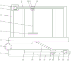
Fig. 1 is a schematic front sectional view of the present invention;
FIG. 2 is a schematic side sectional view of the adjusting base of the present invention;
fig. 3 is a schematic view of a partial structure of the present invention.
In the figure: 1. mounting a base; 2. hinging a shaft; 3. an adjusting base; 4. a mechanical equipment pallet; 5. hoisting a steel rope; 6. hoisting the frame body; 7. mounting a plate; 8. a first servo motor; 9. a drive screw; 10. mounting blocks; 11. a drive nut; 12. a rope reeling roller; 13. a bearing; 14. adjusting the screw rod; 15. a support rod is hinged; 16. a first chute; 17. adjusting the nut; 18. a limiting block; 19. mounting grooves; 20. a second servo motor; 21. a control panel; 22. hooking; 23. a third servo motor; 24. a second chute; 25. a connecting plate; 26. a rotating rod; 27. and (5) hanging a ring.
Detailed Description
The technical solutions in the embodiments of the present invention will be described clearly and completely with reference to the accompanying drawings in the embodiments of the present invention, and it is obvious that the described embodiments are only some embodiments of the present invention, not all embodiments. Based on the embodiments in the present invention, all other embodiments obtained by a person skilled in the art without creative work belong to the protection scope of the present invention.
Referring to fig. 1-3, the present invention provides an embodiment: a double-track type hoisting and transporting frame for mechanical equipment comprises a mounting base 1, an adjusting base 3 and a hoisting frame body 6, wherein a hinged shaft 2 is installed at one end of the top of the mounting base 1, the adjusting base 3 is hinged to the top of the hinged shaft 2, a mounting groove 19 is formed in one end, far away from the hinged shaft 2, of the top of the mounting base 1, the hoisting frame body 6 is installed on two sides of the top of the adjusting base 3, a mounting plate 7 is installed on one side, close to the adjusting base 3, of the hoisting frame body 6, a first servo motor 8 is installed at the middle position, close to one end of the adjusting base 3, of the mounting plate 7, the type of the first servo motor 8 can be SNS-200L, a driving screw 9 is installed at the output end of the first servo motor 8, a second chute 24 is formed in one side, close to the adjusting base 3, of the hoisting frame body 6, and a third servo motor 23 is installed on one side of the installation block 10 far away from the adjusting base 3, wherein the model of the third servo motor 23 can be SNS-200L, the output ends of the third servo motor 23 are all provided with rotating rods 26, a second servo motor 20 is installed at one end of the installation groove 19 far away from the hinge shaft 2, the model of the second servo motor 20 can be SNS-200L, a bearing 13 is installed at one end of the installation groove 19 near the hinge shaft 2, an adjusting screw 14 is installed inside the bearing 13, and adjusting nut 17 is installed to the outside screw thread of adjusting screw 14, and the output of second servo motor 20 is connected with adjusting screw 14 through the pivot, and control panel 21 is installed to the one end of installation base 1 far away from articulated shaft 2, and the output of control panel 21 passes through the wire and respectively with the input electric connection of first servo motor 8, second servo motor 20 and third servo motor 23.
In this implementation:
furthermore, the rotating rod 26 passes through the mounting block 10, the rope winding rollers 12 are mounted on the outer sides of the rotating rod 26, the outer sides of the rope winding rollers 12 are provided with hoisting steel ropes 5 in a winding mode, hooks 22 are mounted at one ends, far away from the rope winding rollers 12, of the hoisting steel ropes 5, the third servo motor 23 drives the rope winding rollers 12 to rotate through the rotating rod 26, the hoisting steel ropes 5 can be wound on the outer sides of the rope winding rollers 12, and therefore the mechanical equipment supporting plate 4 can be lifted upwards to lift the mechanical equipment to a high place.
Further, drive nut 11 is installed to drive screw 9's outside screw thread, and drive nut 11 is connected with connecting plate 25, and first servo motor 8 drives drive screw 9 and rotates at the uniform velocity, can drive couple 22 and remove, and first servo motor 8's rotational speed is invariable, during the start-up, can not produce great impulsive force, and in the transportation, couple 22 moving speed keeps invariable, is difficult for making couple 22 produce great rocking, is favorable to improving the stability of device.
Further, adjusting nut 17's top articulates there is articulated branch 15, and articulated branch 15 keeps away from adjusting nut 17's one end and adjusts base 3 articulated, second servo motor 20 drives adjusting screw 14 clockwise rotation, adjusting nut 17 in the adjusting screw 14 outside receives the spacing of stopper 18, can not follow adjusting screw 14 and rotate together, can only move to bearing 13 one end in adjusting screw 14 outside through the screw thread, adjusting nut 17 drives articulated branch 15 and moves together, make articulated branch 15 atress promote adjusting base 3, make adjusting base 3 atress and rotate as the centre of a circle along its articulated position department with articulated shaft 2, can adjust the inclination of adjusting base 3 and handling support body 6, make the one end of handling support body 6 can incline to higher position department, thereby can carry mechanical equipment to higher position department.
Further, the bottom of mounting groove 19 is provided with first spout 16, and stopper 18 is installed through the slider to first spout 16, and stopper 18 is connected with adjusting nut 17, and is spacing to adjusting nut 17 through stopper 18, can prevent that adjusting nut 17 from following adjusting screw 14 and rotating together.
Further, mechanical equipment layer board 4 is installed to the top of adjusting base 3, and mechanical equipment layer board 4's both sides all install link 27, are convenient for hoist and mount mechanical equipment.
The working principle is as follows: when the lifting steel rope device is used, the mounting base 1 is fixedly mounted at a designated position, then the device is powered on, a worker can fix mechanical equipment needing lifting transportation on the mechanical equipment supporting plate 4, then the first servo motor 8 is started through the control panel 21, the first servo motor 8 drives the driving screw 9 to rotate clockwise or anticlockwise, the driving nut 11 on the outer side of the driving screw 9 is limited by the connecting plate 25 and cannot rotate along with the driving screw 9 but can only move on the outer side of the driving screw 9 through threads, the driving nut 11 drives the connecting plate 25 to slide on the second sliding chute 24, the connecting plate 25 drives the mounting block 10 to move together, namely, the lifting steel rope 5 and the hook 22 can be driven to move together, so that the mechanical equipment supporting plate 4 can be driven by the hook 22 to move to transport the mechanical equipment, when the mechanical equipment is lifted to a high place, the worker can start the third servo motor 23 through the control panel 21, the third servo motor 23 drives the rope collecting roller 12 to rotate through the rotating rod 26, the lifting steel rope 5 can be wound on the outer side of the rope collecting roller 12, so that the mechanical equipment supporting plate 4 can be lifted upwards to lift the mechanical equipment to a high position, when the mechanical equipment needs to be lifted to a higher position, a worker can start the second servo motor 20 through the control panel 21, so that the second servo motor 20 drives the adjusting screw 14 to rotate clockwise, the adjusting nut 17 on the outer side of the adjusting screw 14 is limited by the limiting block 18 and cannot rotate along with the adjusting screw 14, the adjusting nut 17 can only move towards one end of the bearing 13 on the outer side of the adjusting screw 14 through threads, the adjusting nut 17 drives the hinged support rod 15 to move together, the hinged support rod 15 is forced to push the adjusting base 3, the adjusting base 3 is forced to rotate along the hinged position of the adjusting base 3 and the hinged position of the hinged shaft 2 as a circle center, and the inclination angles of the adjusting, so that one end of the lifting frame body 6 can be inclined to a higher position, and the mechanical equipment can be lifted to the higher position.
Although the present invention has been described in detail with reference to the foregoing embodiments, it will be apparent to those skilled in the art that modifications may be made to the embodiments or portions thereof without departing from the spirit and scope of the invention.
Claims (6)
1. The utility model provides a mechanical equipment double track formula is carried and is transported frame, includes mounting base (1), adjusts base (3) and handling support body (6), its characterized in that: the lifting device is characterized in that an articulated shaft (2) is installed at one end of the top of the installation base (1), an adjusting base (3) is hinged to the top of the articulated shaft (2), an installation groove (19) is formed in one end, far away from the articulated shaft (2), of the top of the installation base (1), lifting frame bodies (6) are installed on two sides of the top of the adjusting base (3), an installation plate (7) is installed on one side, close to the adjusting base (3), of each lifting frame body (6), a first servo motor (8) is installed at the middle position, close to one end of the adjusting base (3), of each installation plate (7), a driving screw (9) is installed at the output end of each first servo motor (8), a second sliding groove (24) is formed in one side, close to the adjusting base (3), of each lifting frame body (6), a connecting plate (25) is installed on each second sliding groove (24), and installation piece (10) keep away from one side of adjusting base (3) and all install third servo motor (23), bull stick (26) are all installed to the output of third servo motor (23), mounting groove (19) inside one end of keeping away from articulated shaft (2) installs second servo motor (20), and mounting groove (19) inside one end of being close to articulated shaft (2) installs bearing (13), the internally mounted of bearing (13) has adjusting screw (14), and adjusting screw (14)'s outside screw thread installs adjusting nut (17), the output of second servo motor (20) is connected with adjusting screw (14) through the pivot, control panel (21) are installed to the one end of keeping away from articulated shaft (2) in mounting base (1), the output of control panel (21) pass through the wire respectively with first servo motor (8), The input ends of the second servo motor (20) and the third servo motor (23) are electrically connected.
2. The double-track type overhead transportation carrier of mechanical equipment according to claim 1, wherein: the utility model discloses a rope winding machine, including the installation piece (10), the installation piece (10) is all passed in bull stick (26), and receipts rope roller (12) are all installed in the outside of bull stick (26), the outside of receipts rope roller (12) all around being equipped with handling steel cable (5), and the couple (22) are all installed to the one end that receives rope roller (12) is kept away from in handling steel cable (5).
3. The double-track type overhead transportation carrier of mechanical equipment according to claim 1, wherein: and a driving nut (11) is installed on the outer side of the driving screw (9) in a threaded manner, and the driving nut (11) is connected with the connecting plate (25).
4. The double-track type overhead transportation carrier of mechanical equipment according to claim 1, wherein: the top of adjusting nut (17) is articulated to have articulated branch (15), and articulated branch (15) keep away from the one end of adjusting nut (17) and adjust base (3) articulated.
5. The double-track type overhead transportation carrier of mechanical equipment according to claim 1, wherein: the bottom of mounting groove (19) is provided with first spout (16), and stopper (18) are installed through the slider in first spout (16), stopper (18) are connected with adjusting nut (17).
6. The double-track type overhead transportation carrier of mechanical equipment according to claim 1, wherein: mechanical equipment layer board (4) are installed to the top of adjusting pedestal (3), and link (27) are all installed to the both sides of mechanical equipment layer board (4).
Priority Applications (1)
| Application Number | Priority Date | Filing Date | Title |
|---|---|---|---|
| CN202021404793.0U CN212831061U (en) | 2020-07-16 | 2020-07-16 | Mechanical equipment double-track type suspended transportation frame |
Applications Claiming Priority (1)
| Application Number | Priority Date | Filing Date | Title |
|---|---|---|---|
| CN202021404793.0U CN212831061U (en) | 2020-07-16 | 2020-07-16 | Mechanical equipment double-track type suspended transportation frame |
Publications (1)
| Publication Number | Publication Date |
|---|---|
| CN212831061U true CN212831061U (en) | 2021-03-30 |
Family
ID=75117520
Family Applications (1)
| Application Number | Title | Priority Date | Filing Date |
|---|---|---|---|
| CN202021404793.0U Expired - Fee Related CN212831061U (en) | 2020-07-16 | 2020-07-16 | Mechanical equipment double-track type suspended transportation frame |
Country Status (1)
| Country | Link |
|---|---|
| CN (1) | CN212831061U (en) |
-
2020
- 2020-07-16 CN CN202021404793.0U patent/CN212831061U/en not_active Expired - Fee Related
Similar Documents
| Publication | Publication Date | Title |
|---|---|---|
| CN215558428U (en) | Anti-collision crane capable of effectively preventing goods from being unhooked | |
| CN214270030U (en) | Automatic change mechanical hoist | |
| CN212831061U (en) | Mechanical equipment double-track type suspended transportation frame | |
| CN212687398U (en) | Crane for small building | |
| CN206901604U (en) | Double-hung rotation vehicle of crane | |
| CN219031531U (en) | Electromagnetic double-beam bridge crane | |
| CN218665040U (en) | Movable gantry crane device | |
| CN216512394U (en) | Crane with anti-swing device | |
| CN217676476U (en) | Lifting device convenient to adjust rotation angle | |
| CN216807878U (en) | Jacket ceiling hoisting device | |
| CN210286537U (en) | Four-point crane for hoisting bin cover of transport ship | |
| CN210048398U (en) | Light cantilever crane for industrial machinery | |
| CN213536983U (en) | Novel adjustable lifting appliance | |
| CN213505648U (en) | Hoisting equipment for steel structure engineering | |
| CN210528295U (en) | Multifunctional transportation device | |
| CN209098065U (en) | A kind of loop wheel machine with mounting plate Guiding wheel structure | |
| CN113734982A (en) | European style double-beam crane | |
| CN113697683A (en) | Equipment part replacement lifting appliance | |
| CN219823464U (en) | Crane installation auxiliary device | |
| CN218507351U (en) | Hoisting mechanism for freight container | |
| CN220300239U (en) | Shipbuilding gantry crane | |
| CN220502498U (en) | Aluminum alloy decoration hoisting mechanism | |
| CN205916920U (en) | Walking hoist and mount boat car | |
| CN218619924U (en) | Double-beam bridge crane for transferring calcium carbide pots | |
| CN205773138U (en) | A kind of charging crane of carrying implement |
Legal Events
| Date | Code | Title | Description |
|---|---|---|---|
| GR01 | Patent grant | ||
| GR01 | Patent grant | ||
| CF01 | Termination of patent right due to non-payment of annual fee |
Granted publication date: 20210330 Termination date: 20210716 |
|
| CF01 | Termination of patent right due to non-payment of annual fee |