CN212744174U - Throttling element suitable for conical joint and liquid rocket - Google Patents
Throttling element suitable for conical joint and liquid rocket Download PDFInfo
- Publication number
- CN212744174U CN212744174U CN202020967730.XU CN202020967730U CN212744174U CN 212744174 U CN212744174 U CN 212744174U CN 202020967730 U CN202020967730 U CN 202020967730U CN 212744174 U CN212744174 U CN 212744174U
- Authority
- CN
- China
- Prior art keywords
- conical
- filler neck
- ball joint
- throttling element
- joint
- Prior art date
- Legal status (The legal status is an assumption and is not a legal conclusion. Google has not performed a legal analysis and makes no representation as to the accuracy of the status listed.)
- Active
Links
Images


Landscapes
- Joints Allowing Movement (AREA)
Abstract
The utility model provides a throttling element and a liquid rocket suitable for a conical joint, which comprises a spherical joint, a conical filler neck, a throttling device and a locking piece; wherein, along axial direction ball joint's bulb end with the inboard butt of toper filler neck, the throttler includes the different first portion of external diameter dimension and second part along the axis direction, the throttler is kept away from the ball joint the first portion outside with the inner wall of toper filler neck is hugged closely each other, the throttler passes through the second part sets up the ball joint with it is fixed between the toper inboard, the retaining member is located the ball joint with the toper filler neck outside, and be used for adjusting the ball joint with axial distance between the toper filler neck is used for realizing the ball joint with sealed between the toper filler neck, the utility model discloses a throttling element is convenient for dismantle, change, can improve sealing performance, safe and reliable.
Description
Technical Field
The utility model relates to a rocket throttling arrangement field especially relates to a throttling element and liquid rocket suitable for conical joint.
Background
With the change of science and technology, the related technology in the aerospace field is also rapidly developed. In liquid rocket engines, sonic nozzles or orifice plates are often used to facilitate control of the medium flow in the liquid/gas circuit system. Furthermore, the throttle element is versatile for different adjustment requirements. For example, chinese patent CN105386894B discloses a high-pressure high-transformation-ratio flow regulating valve, which drives a flow regulating system by a stepping motor. The flow regulating system consists of a regulating rod, a throttle orifice plate and a pressing plate, wherein the throttle orifice plate is fixed in the shell through the pressing plate, and a detachable structure is arranged between the pressing plate and the shell. However, a gap exists between the orifice plate and the housing, so that the liquid/gas medium may leak from the pipeline, which causes a safety hazard. Chinese patent CN109723839A discloses a ball-head type orifice plate and a throttling element, which comprises a hollow cylinder with a first cavity inside, a ball head connected with the hollow cylinder and having a through ball-head cavity, wherein the aperture of the first end of the ball-head cavity is larger than that of the second end of the ball-head cavity, and the throttling element is not convenient to detach and replace when in use.
Therefore, there is a need to develop a throttling element suitable for a taper joint and easy to detach and replace, so as to improve the throttling and sealing performance of the throttling element.
Disclosure of Invention
In view of this, the technical problem to be solved by the present invention is to provide a throttling element and a liquid rocket suitable for a taper joint, which have the characteristics of easy detachment and replacement, and can improve the throttling and sealing performance.
In order to solve the above technical problem, embodiments of the present invention provide: a throttling element suitable for a conical joint comprises a spherical joint, a conical filler neck, a throttling device and a locking piece; the ball end of the ball joint is abutted with the inner side of the cone of the conical filler neck along the axial direction, the throttle comprises a first part and a second part which are different in outer diameter dimension along the axial direction, the outer side of the first part, far away from the ball joint, of the throttle is tightly attached to the inner wall of the conical filler neck, the throttle is fixedly arranged between the ball joint and the inner side of the cone through the second part, the locking piece is located on the outer sides of the ball joint and the conical filler neck and used for adjusting the axial distance between the ball joint and the conical filler neck, and sealing between the ball joint and the conical filler neck is achieved.
Further, the restrictor has a passage along the axis that communicates at both ends for liquid/gas communication.
Further, the first part is a cylindrical section, the second part is a conical section, and the throttle is fixed through a gap formed by at least partially placing the conical section between the ball head part of the ball joint and the conical inner side of the conical filler neck.
Further, the first portion and the second portion are integrally formed.
Further, the aperture of the channel is smaller than the diameter of the inner cavity of the conical filler neck.
Furthermore, the conical surface angle of the conical filler neck close to the conical section is larger than that of the conical section.
Further, the retaining member is external nut structure, toper filler neck surface is equipped with the cooperation the fixed external screw thread of external nut structure, external nut structure through along the internal thread of its axial one side with the external screw thread cooperation.
Furthermore, one side of the outer nut structure, which is far away from the conical filler neck, is sleeved on the surface of the spherical joint.
Furthermore, the spherical joint is far away from the bulb outside of throttle still be equipped with spherical joint integrated into one piece's first annular is protruding, the outer nut structure is kept away from the one end of throttle is equipped with inward second annular is protruding, the second annular is protruding from first annular is protruding to be kept away from throttle side with first annular is protruding to cooperate.
Another aspect of the present invention is to provide a liquid rocket including the features of the throttling element for a taper joint described above.
Compared with the prior art, the beneficial effects of the utility model are that at least:
the throttling element suitable for the conical joint comprises a spherical joint, a conical filler neck, a throttler and a locking piece.
Because the throttleer includes first part and the second part that the external diameter size is different along the axis direction, the throttleer is kept away from ball joint the first part outside with the inner wall of toper filler neck is hugged closely each other for first part is fixed firm, avoids rocking because of first part and causes the damage to the inner wall of toper filler neck, guarantees first part and toper filler neck's is intact.
Because along axial direction the bulb end of ball joint with the inboard butt of toper filler neck, the choke ware passes through the second part setting is in ball joint with it is fixed inboard between the toper, the second part is in ball joint with between the toper, avoid the second part to appear the displacement removal, make the second part fixed firm simultaneously, avoid appearing rocking, and then conveniently to the flow control of liquid/gaseous medium.
Because the retaining member is positioned on the outer sides of the spherical joint and the conical filler neck, the sealing tightness between the spherical joint and the conical filler neck is ensured by adjusting the axial distance between the spherical joint and the conical filler neck, and the conical filler neck is convenient to disassemble.
The whole structure is convenient to detach and replace, can improve the sealing performance, and is safe and reliable.
Drawings
The accompanying drawings, which are incorporated in and constitute a part of the specification of the invention, illustrate exemplary embodiments of the invention and together with the description, serve to explain the principles of the invention.
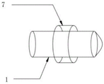
FIG. 1 is a cross-sectional view of a throttling element suitable for use in a taper joint in accordance with the present invention;
fig. 2 is a schematic structural diagram of the first part and the second part of the present invention;
FIG. 3 is a front view of the locking member of the present invention;
FIG. 4 is a right side view of the locking member of the present invention;
fig. 5 is a perspective view of the ball joint of the present invention.
Description of reference numerals:
1 spherical joint 2 conical filler neck
3 throttle 4 locking piece
5 first part 6 second part
7 first annular projection 8 second annular projection
Detailed Description
To make the objects, technical solutions and advantages of the embodiments of the present invention more apparent, the spirit of the present invention will be described in detail with reference to the accompanying drawings, and any person skilled in the art can change or modify the techniques taught by the present invention without departing from the spirit and scope of the present invention after understanding the embodiments of the present invention.
The exemplary embodiments and descriptions of the present invention are provided to explain the present invention, but not to limit the present invention. Additionally, the same or similar numbered elements/components used in the drawings and the embodiments are used to represent the same or similar parts.
As used herein, the terms "first," "second," …, etc. do not denote any order or sequential importance, nor are they used to limit the invention, but rather are used to distinguish one element from another or from another element or operation described in the same technical language.
With respect to directional terminology used herein, for example: up, down, left, right, front or rear, etc., are simply directions with reference to the drawings. Accordingly, the directional terminology used is intended to be illustrative and is not intended to be limiting of the present teachings.
As used herein, the terms "comprising," "including," "having," "containing," and the like are open-ended terms that mean including, but not limited to.
As used herein, "and/or" includes any and all combinations of the described items.
References to "plurality" herein include "two" and "more than two"; reference to "multiple sets" herein includes "two sets" and "more than two sets".
As used herein, the terms "substantially", "about" and the like are used to modify any slight variation in quantity or error that does not alter the nature of the variation. Generally, the range of slight variations or errors modified by such terms may be 20% in some embodiments, 10% in some embodiments, 5% in some embodiments, or other values. It should be understood by those skilled in the art that the aforementioned values can be adjusted according to actual needs, and are not limited thereto.
Certain words used to describe the present application are discussed below or elsewhere in this specification to provide additional guidance to those skilled in the art in describing the present application.
Fig. 1 is a cross-sectional view of a throttling element suitable for a taper joint according to an embodiment of the present invention. Referring to fig. 1, the throttling element comprises a ball joint, a conical filler neck 2, a restrictor 3 and a locking member 4. Wherein, the ball end of the ball joint 1 along the axial direction is abutted against the conical inner side of the conical filler neck 2, so that the conical inner side and the ball end form a seal. The flow restrictor 3 comprises a first part 6 and a second part 5 with different outer diameter sizes along the axial direction, wherein the first part 6 is used for reducing the pipe diameter of the inner wall of the conical filler neck to achieve the throttling effect, and the second part 5 is used for assisting the fixation of the flow restrictor 3 in the throttling element. The outer side of a first part 6 of the throttler 3, which is far away from the spherical joint 1, is tightly attached to the inner wall of the conical filler neck, and the throttler 3 is arranged between the spherical joint 1 and the inner side of the cone through a second part 5 and is fixed. The locking piece 4 is positioned outside the ball joint 1 and the conical filler neck 2 and is used for adjusting the axial distance between the ball joint 1 and the conical filler neck 2 so as to realize the sealing between the ball joint 1 and the conical filler neck 2.
Specifically, the method comprises the following steps: the throttling element of the design consists of a spherical joint 1, a conical filler neck 2, a throttling device 3 and a locking piece 4. Since the restrictor 3 comprises a first part 6 and a second part 5 with different outer diameter dimensions in the axial direction, the outer side of the first part 6 of the restrictor 3 away from the ball joint 1 can be tightly attached to the inner wall of the conical filler neck 2, thereby performing the function of throttling the conical filler neck 2. Furthermore, the conical portion of the conical filler neck 2 can serve as a guide for easy installation of the restrictor 3. The equal diameter position of the inner wall of the conical filler neck 2 can ensure that the first part 6 is fixed firmly, the damage to the inner wall of the conical filler neck 2 caused by the shaking of the first part 6 is avoided, and the integrity of the first part 6 and the conical filler neck 2 is ensured.
Since the ball end of the ball joint 1 abuts against the conical inner side of the conical filler neck 2 in the axial direction, the throttle 3 can be fixed by the second part 5 arranged between the ball joint 1 and the conical inner side. The second part 5 has avoided the second part 5 to appear the displacement and has removed between ball joint 1 and the toper, makes the second part 5 fixed firm simultaneously, avoids appearing rocking, and then can realize the flow control to liquid/gaseous medium steadily.
It should be noted that the joint end of the conical filler neck 2 and the ball head portion of the ball joint 1 is a conical structure, i.e. a structure with an increasingly enlarged bore diameter, and the ball head portion abuts against the inner side of the conical structure along the axial direction, so that the ball head and the inner side of the conical structure form a seal. In this embodiment, the minimum radial dimension of the tapered inner side may be smaller than the diameter of the ball head, so that after the ball head abuts against the tapered inner side, the side of the ball head in the axial direction close to the throttle 3 forms a gap with the inner side of the small diameter end of the tapered inner side, and the second portion 5 of the throttle 3 may be fittingly disposed in the gap, thereby assisting the fixation of the throttle 3 in the throttle element.
In addition, because the retaining member 4 is located outside the spherical joint 1 and the conical filler neck 2, by adjusting the axial distance between the spherical joint 1 and the conical filler neck 2, the sealing tightness between the spherical joint 1 and the conical filler neck 2 can be ensured, and the disassembly is convenient. The whole structure can be universally applied to the standard pipe connecting piece structure, only the throttler 3 needs to be replaced when the throttling element is adjusted, other structures of a pipeline are not affected, the repeated production of the pipe connecting piece caused by adjusting the throttling aperture is avoided, the waste is reduced, and the management is easy.
It should be noted that, in order to facilitate the flow rate adjustment of the liquid/gas medium by the restrictor 3, the liquid/gas medium is communicated, for example, the restrictor 3 has a passage communicating with both ends along the axis for the liquid/gas communication. The minimum passage size of the passage is smaller than the inner diameter size of the conical filler neck 2, so that the throttling purpose is realized.
It should be noted that, as shown in fig. 1 and fig. 2, for convenience of use and convenience of fixing, in the present embodiment, the first portion 6 may be a cylindrical section, and the second portion 5 may be a conical section integrally formed with the cylindrical section. In order to ensure that the throttle 3 is securely fixed and at the same time improve the tightness of the throttle 3 with respect to the conical filler neck 2 during use, the throttle 3 is fixed, for example, by a conical section at least partially in the gap between the ball head of the ball joint 1 and the conical inner side of the conical filler neck 2. In order to facilitate the fixation, the conical section is tightly connected with the conical filler neck 2, and the conical section is prevented from damaging the conical filler neck 2, for example, the conical section and the cylindrical section are uniformly transited.
It is worth mentioning that, in order to ensure that the first portion 6 and the second portion 5 are connected tightly and fixed more firmly, for example, the first portion 6 and the second portion 5 can be integrally formed, so as to prevent the first portion 6 and the second portion 5 from cracking due to liquid/gas medium impact or long-term use, ensure the stability of the restrictor 3, and facilitate application.
As mentioned above, the aperture of the channel of the restrictor is smaller than the diameter of the inner cavity of the conical filler neck 2 to achieve the throttling effect. In addition, the channel of the restrictor may be designed to have a single-hole structure or a multi-hole structure according to actual needs, which are not illustrated herein. Further, the passageway of the restrictor may be circular, oval, etc.
It should be mentioned that, as shown in fig. 1, the installation and removal of the restrictor 3 is facilitated while avoiding scratching the conical surface of the conical filler neck 2, for example, the conical angle of the conical filler neck 2 near the conical section is greater than the conical angle of the conical section.
In addition, in practical use, the restrictor 3 and the conical filler neck 2 may be integrally formed in order to improve the stability of the installation of the restrictor 3. For convenient installation and disassembly, one end of the restrictor 3 and the conical filler neck 2 can also adopt a threaded connection form.
Specifically, as shown in fig. 1, 4 and 5, in order to facilitate adjustment, the locking member 4 is securely fixed to the tapered filler neck 2, for example, the locking member 4 has an external nut structure, and the tapered filler neck 2 is provided on a surface thereof with an external thread fixed to the external nut structure, and the external nut structure is engaged with the external thread through an internal thread along one side in an axial direction thereof.
In addition, as shown in fig. 1, 3 and 5, for convenience of disassembly and fixation, for example, the side of the external nut structure far from the conical nipple 2 is sleeved on the surface of the ball joint 1. For example, the ball head outer side of the spherical joint 1 far away from the throttle 3 is further provided with a first annular bulge 7 integrally formed with the spherical joint 1, one end of the outer nut structure far away from the throttle 3 in the circumferential direction is provided with an inward second annular bulge 8, and the second annular bulge 8 is matched with the first annular bulge 7 from the side of the first annular bulge 7 far away from the throttle 3. The outer nut drives the second annular bulge 8 to move in the adjusting process, and the second annular bulge 8 drives the first annular bulge 7 to move towards the conical filler neck 2 after being abutted against the first annular bulge 7, so that the whole structure is reasonable in design, and the outer nut is convenient to mount and dismount.
The above embodiments may be combined with each other with corresponding technical effects.
The utility model is suitable for a conical joint's throttling element can be used for gaseous, liquid medium's flow control.
Another aspect of the present invention is to provide a liquid rocket including the above technical features of the throttling element adapted for a cone joint, and having corresponding technical effects.
The foregoing is only an illustrative embodiment of the present invention, and any equivalent changes and modifications made by those skilled in the art without departing from the spirit and principles of the present invention should fall within the protection scope of the present invention.
Claims (10)
1. A throttling element adapted for use in a taper joint, comprising: comprises a spherical joint, a conical filler neck, a restrictor and a locking piece; the ball end of the ball joint is abutted with the inner side of the cone of the conical filler neck along the axial direction, the throttle comprises a first part and a second part which are different in outer diameter dimension along the axial direction, the outer side of the first part, far away from the ball joint, of the throttle is tightly attached to the inner wall of the conical filler neck, the throttle is fixedly arranged between the ball joint and the inner side of the cone through the second part, the locking piece is located on the outer sides of the ball joint and the conical filler neck and used for adjusting the axial distance between the ball joint and the conical filler neck, and sealing between the ball joint and the conical filler neck is achieved.
2. A throttling element for a cone fitting according to claim 1, wherein: the restrictor has a passage along the axis communicating at both ends for liquid/gas communication.
3. A throttling element for a cone fitting according to claim 2, wherein: the aperture of the channel is smaller than the diameter of the inner cavity of the conical filler neck.
4. A throttling element for a cone fitting according to claim 1, wherein: the first part is a cylindrical section, the second part is a conical section, and the throttle is fixed through a gap formed by at least partially arranging the conical section between the ball head part of the spherical joint and the conical inner side of the conical filler neck.
5. A throttling element for a cone fitting according to claim 4, wherein: the conical surface angle of the conical filler neck close to the conical section is larger than that of the conical section.
6. A throttling element for a cone fitting according to claim 1, wherein: the first portion and the second portion are integrally formed.
7. A throttling element for a cone fitting according to claim 1, wherein: the retaining member is external nut structure, toper filler neck surface is equipped with the cooperation the fixed external screw thread of external nut structure, external nut structure through along the internal thread of its axial one side with the external screw thread cooperation.
8. A throttling element for a cone fitting according to claim 7, wherein: one side of the outer nut structure, which is far away from the conical filler neck, is sleeved on the surface of the spherical joint.
9. A throttling element for a cone fitting according to claim 8, wherein: the ball joint is kept away from the bulb outside of choke ware still be equipped with ball joint integrated into one piece's first annular is protruding, the outer nut structure is kept away from the one end of choke ware is equipped with inward second annular is protruding, second annular is protruding to be followed first annular is protruding to be kept away from choke ware side with first annular is protruding to cooperate.
10. A liquid rocket comprising a throttling element adapted for a conical joint according to any one of claims 1 to 9.
Priority Applications (1)
| Application Number | Priority Date | Filing Date | Title |
|---|---|---|---|
| CN202020967730.XU CN212744174U (en) | 2020-06-01 | 2020-06-01 | Throttling element suitable for conical joint and liquid rocket |
Applications Claiming Priority (1)
| Application Number | Priority Date | Filing Date | Title |
|---|---|---|---|
| CN202020967730.XU CN212744174U (en) | 2020-06-01 | 2020-06-01 | Throttling element suitable for conical joint and liquid rocket |
Publications (1)
| Publication Number | Publication Date |
|---|---|
| CN212744174U true CN212744174U (en) | 2021-03-19 |
Family
ID=75006379
Family Applications (1)
| Application Number | Title | Priority Date | Filing Date |
|---|---|---|---|
| CN202020967730.XU Active CN212744174U (en) | 2020-06-01 | 2020-06-01 | Throttling element suitable for conical joint and liquid rocket |
Country Status (1)
| Country | Link |
|---|---|
| CN (1) | CN212744174U (en) |
Cited By (1)
| Publication number | Priority date | Publication date | Assignee | Title |
|---|---|---|---|---|
| CN114130461A (en) * | 2021-11-05 | 2022-03-04 | 中国建筑第五工程局有限公司 | Roller cleaning and cavity cleaning system of viscous shield muck crushing and refining equipment |
-
2020
- 2020-06-01 CN CN202020967730.XU patent/CN212744174U/en active Active
Cited By (2)
| Publication number | Priority date | Publication date | Assignee | Title |
|---|---|---|---|---|
| CN114130461A (en) * | 2021-11-05 | 2022-03-04 | 中国建筑第五工程局有限公司 | Roller cleaning and cavity cleaning system of viscous shield muck crushing and refining equipment |
| CN114130461B (en) * | 2021-11-05 | 2022-12-13 | 中国建筑第五工程局有限公司 | Roller cleaning and cavity cleaning system of viscous shield muck crushing and refining equipment |
Similar Documents
| Publication | Publication Date | Title |
|---|---|---|
| US20160295924A1 (en) | Electronic Cigarette Atomizer, Electronic Cigarette and Assembly Method of Electronic Cigarette Atomizer | |
| CN212744174U (en) | Throttling element suitable for conical joint and liquid rocket | |
| CN105202288A (en) | Pipe connector | |
| CN109357050B (en) | A kind of one-way cock with self-locking function | |
| JPH11280976A (en) | Joint | |
| CN112065996B (en) | Hole detector plug device and hole detector plug assembly and disassembly tools | |
| CN216834307U (en) | Fuel oil diffuser | |
| CN206874914U (en) | A kind of motor-driven valve and the heat exchanger assembly with the motor-driven valve | |
| CN210014026U (en) | Ball-head type throttling orifice plate and throttling element | |
| CN104534217A (en) | Union elbow capable of being assembled with adjustable angle | |
| CN214466778U (en) | Pipe joint for adjusting horizontal state of valve | |
| CN220286679U (en) | Hydraulic pipe joint | |
| CN207830789U (en) | A kind of fastening-pressing type hose attachment device | |
| CN211145502U (en) | Electromagnetic valve body for gas emergency shut-off valve | |
| CN217401964U (en) | Carrier rocket minor diameter pipeline seal structure | |
| CN215847949U (en) | Mounting tool and device | |
| CN219666502U (en) | Sealing washer installation frock | |
| CN220286786U (en) | Adjustable pipeline seal head | |
| CN204935449U (en) | The common-rail injector entering interior oil return type in a kind of passes in and out oily frock | |
| CN210440727U (en) | PP-RCT carbon fiber antistatic pipe | |
| CN215334967U (en) | High-sensitivity ultrahigh-pressure stop valve of automobile correction instrument | |
| CN217762549U (en) | Pneumatic pipe joint | |
| CN213360767U (en) | Bolt and nut assembly with thread protection function | |
| CN214306404U (en) | Grease gun head | |
| CN220816619U (en) | Valve seat assembly of spherical rotary valve |
Legal Events
| Date | Code | Title | Description |
|---|---|---|---|
| GR01 | Patent grant | ||
| GR01 | Patent grant |