CN212716632U - Shield tail brush capable of being rapidly disassembled and replaced - Google Patents
Shield tail brush capable of being rapidly disassembled and replaced Download PDFInfo
- Publication number
- CN212716632U CN212716632U CN202021298016.2U CN202021298016U CN212716632U CN 212716632 U CN212716632 U CN 212716632U CN 202021298016 U CN202021298016 U CN 202021298016U CN 212716632 U CN212716632 U CN 212716632U
- Authority
- CN
- China
- Prior art keywords
- shield tail
- tail brush
- groove
- bolt
- hole
- Prior art date
- Legal status (The legal status is an assumption and is not a legal conclusion. Google has not performed a legal analysis and makes no representation as to the accuracy of the status listed.)
- Expired - Fee Related
Links
- 238000009434 installation Methods 0.000 claims abstract description 11
- 238000003466 welding Methods 0.000 abstract description 4
- 238000009412 basement excavation Methods 0.000 description 2
- 230000004075 alteration Effects 0.000 description 1
- 230000009286 beneficial effect Effects 0.000 description 1
- 238000010586 diagram Methods 0.000 description 1
- 239000000463 material Substances 0.000 description 1
- 238000012986 modification Methods 0.000 description 1
- 230000004048 modification Effects 0.000 description 1
- 239000002689 soil Substances 0.000 description 1
- 238000006467 substitution reaction Methods 0.000 description 1
- XLYOFNOQVPJJNP-UHFFFAOYSA-N water Substances O XLYOFNOQVPJJNP-UHFFFAOYSA-N 0.000 description 1
Images


Landscapes
- Lining And Supports For Tunnels (AREA)
Abstract
The utility model discloses a can dismantle shield tail brush of change fast, including installation base, locating plate, first action bars, shield tail brush base and second action bars, installation base left side is provided with the constant head tank, and the inside swing joint of constant head tank has the pulley to bolted connection has the connecting rod in the middle of the pulley, and connecting rod right side bolted connection has the connecting block simultaneously, the inside first through-hole that is provided with of locating plate, and swing joint has connecting bolt in the first through-hole to connecting bolt swing joint has the second through-hole, and connecting bolt bottom threaded connection is in the thread groove simultaneously, the second through-hole sets up inside the connecting plate, and the welding of connecting plate right side has shield tail brush base. This can dismantle shield tail brush of changing fast adopts operable formula location structure, can fix shield tail brush temporarily so that change shield tail brush, and the gripping structure who sets up simultaneously on shield tail brush base can be when operating personnel changes shield tail brush, and is convenient operate shield tail brush.
Description
Technical Field
The utility model relates to a shield tail brush technical field specifically is a shield tail brush that can dismantle change fast.
Background
With the development of society, more and more cities begin to build subway traffic lines, and when constructing a subway tunnel, a subway tunnel shield machine needs to be used for tunnel excavation, and when the subway tunnel shield machine carries out tunnel excavation operation, a shield tail brush needs to be used for preventing materials such as water, soil and the like from entering the shield from the shield tail.
The current shield tail brush can inevitably be worn and torn in the use, so need often change, but inconvenient dismantlement and the installation of current shield tail brush when changing is consuming time spent when changing and installing the shield tail brush, and current shield tail brush lacks gripping structure, inconvenient operation when installation and dismantlement simultaneously. In order to solve the problems, innovative design is urgently needed on the basis of the original shield tail brush capable of being rapidly disassembled and replaced.
SUMMERY OF THE UTILITY MODEL
An object of the utility model is to provide a can dismantle shield tail brush of change fast to inconvenient dismantlement and the installation and the problem that lacks the gripping structure when providing the change among the above-mentioned background art are solved.
In order to achieve the above object, the utility model provides a following technical scheme: a shield tail brush capable of being rapidly disassembled and replaced comprises an installation base, a positioning plate, a first operating rod, a shield tail brush base and a second operating rod, wherein the left side of the installation base is provided with a positioning groove, the inside of the positioning groove is movably connected with a pulley, the middle of the pulley is connected with a connecting rod through a bolt, the right side of the connecting rod is connected with a connecting block through a bolt, the right side of the connecting block is connected with the positioning plate through a bolt, the two sides of the positioning plate are welded with limiting blocks, the top of each limiting block is connected with a hydraulic column and a ring spring through a bolt, the top of each hydraulic column and the top of each ring spring are connected with the inside of a limiting groove through a bolt, the inside of the positioning plate is provided with a first through hole, the inside of the first through hole is movably connected with a connecting bolt, the connecting, and shield tail brush base top is provided with the recess, and shield tail brush base bottom welding has shield tail brush main part simultaneously.
Preferably, the locating slot is arranged at the center of the mounting base, and the pulley in the locating slot forms a sliding structure with the locating plate through the connecting rod and the connecting block.
Preferably, the center of the top of the positioning plate is connected with a first operating rod through a bolt, and the top of the first operating rod is cylindrical.
Preferably, the limiting blocks are axially and symmetrically distributed relative to the positioning groove, and the limiting blocks and the limiting groove form a sliding structure through the hydraulic column and the annular spring.
Preferably, the connecting bolts are distributed symmetrically about the positioning groove axis, and the inner walls of the connecting bolts, which are connected with the first through holes and the second through holes, are smooth structures.
Preferably, the inner portion of the groove is connected with a second operating rod through a bolt, and the second operating rod is equidistantly distributed inside the groove.
Compared with the prior art, the beneficial effects of the utility model are that: the shield tail brush capable of being rapidly disassembled and replaced adopts the operable positioning structure, the shield tail brush can be temporarily fixed so as to be convenient to replace, and meanwhile, the grabbing structure arranged on the shield tail brush base can be used for conveniently operating the shield tail brush when an operator replaces the shield tail brush;
1. the temporary positioning structure is arranged, the positioning plate can be pulled upwards through the first operating rod, so that the limiting blocks connected to the two sides of the positioning plate temporarily fix the connecting plate connected to the base of the shield tail brush under the action force of the hydraulic column and the annular spring, and an operator can conveniently detach and install the shield tail brush;
2. be provided with gripping structure, can make operating personnel when changing the shield tail brush, for operating personnel provides borrow power point to operating personnel removes and changes the shield tail brush.
Drawings
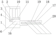
FIG. 1 is a front view of the cross-sectional structure of the present invention;
FIG. 2 is a schematic side sectional view of the present invention;
FIG. 3 is a schematic diagram of the structure of the right side view of the present invention;
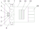
fig. 4 is a schematic top sectional view of the present invention.
In the figure: 1. installing a base; 2. positioning a groove; 3. a pulley; 4. a connecting rod; 5. connecting blocks; 6. positioning a plate; 7. a limiting block; 8. a hydraulic column; 9. an annular spring; 10. a limiting groove; 11. a first operating lever; 12. a first through hole; 13. a connecting bolt; 14. a second through hole; 15. a thread groove; 16. a connecting plate; 17. a shield tail brush base; 18. a groove; 19. a second operating lever; 20. the shield tail brush main part.
Detailed Description
The technical solutions in the embodiments of the present invention will be described clearly and completely with reference to the accompanying drawings in the embodiments of the present invention, and it is obvious that the described embodiments are only some embodiments of the present invention, not all embodiments. Based on the embodiments in the present invention, all other embodiments obtained by a person skilled in the art without creative work belong to the protection scope of the present invention.
Referring to fig. 1-4, the present invention provides a technical solution: a shield tail brush capable of being rapidly disassembled and replaced comprises an installation base 1, a positioning groove 2, a pulley 3, a connecting rod 4, a connecting block 5, a positioning plate 6, a limiting block 7, a hydraulic column 8, an annular spring 9, a limiting groove 10, a first operating rod 11, a first through hole 12, a connecting bolt 13, a second through hole 14, a thread groove 15, a connecting plate 16, a shield tail brush base 17, a groove 18, a second operating rod 19 and a shield tail brush main body 20, wherein the positioning groove 2 is arranged on the left side of the installation base 1, the pulley 3 is movably connected inside the positioning groove 2, the connecting rod 4 is connected in the middle of the pulley 3 through a bolt, the connecting block 5 is connected on the right side of the connecting rod 4 through a bolt, the right side of the connecting block 5 is connected to the positioning plate 6 through a bolt, the limiting block 7 is welded on two sides of the positioning plate 6, the hydraulic column 8 and the annular spring 9 are, inside being provided with first through-hole 12 of locating plate 6, and swing joint has connecting bolt 13 in the first through-hole 12 to connecting bolt 13 swing joint has second through-hole 14, and connecting bolt 13 bottom threaded connection is in thread groove 15 simultaneously, and second through-hole 14 sets up inside connecting plate 16, and the welding of connecting plate 16 right side has shield tail brush base 17, and shield tail brush base 17 top is provided with recess 18, and shield tail brush base 17 bottom welding has shield tail brush main part 20 simultaneously.
In the embodiment, the positioning groove 2 is arranged at the central position of the mounting base 1, and the pulley 3 in the positioning groove 2 and the positioning plate 6 form a sliding structure through the connecting rod 4 and the connecting block 5;
the first operating rod 11 is connected to the center of the top of the positioning plate 6 through a bolt, the top of the first operating rod 11 is cylindrical, and the structural design facilitates that when the shield tail brush main body 20 is replaced, the positioning plate 6 can be lifted upwards through the first operating rod 11 so as to replace the shield tail brush main body 20;
the limiting blocks 7 are distributed in an axisymmetric mode relative to the positioning groove 2, the limiting blocks 7 and the limiting grooves 10 form a sliding structure through the hydraulic columns 8 and the annular springs 9, the structural design can enable the positioning plate 6 to move in the positioning groove 2 through the limiting blocks 7 when the shield tail brush main body 20 is replaced, and meanwhile, the positioning plate 6 can position the connecting plate 16 under the acting force of the hydraulic columns 8 and the annular springs 9 when the shield tail brush main body 20 is installed;
the connecting bolts 13 are distributed in an axisymmetrical manner relative to the positioning groove 2, and the inner walls of the connecting bolts 13, which are connected with the first through holes 12 and the second through holes 14, are smooth structures, so that the connecting bolts 13 can fix the positioning plate 6 and the connecting plate 16 at the bottom of the mounting base 1 through the thread grooves 15, and meanwhile, the inner walls of the first through holes 12 and the second through holes 14 are smooth structures, so that the connecting bolts 13 can be quickly connected to the thread grooves 15;
the second operating rods 19 are connected to the inner portion of the groove 18 through bolts, the second operating rods 19 are distributed inside the groove 18 at equal intervals, and due to the structural design, when the shield tail brush main body 20 is replaced, the shield tail brush base 17 can be operated through the second operating rods 19.
The working principle is as follows: when the device is used, as shown in fig. 1-4, firstly, the connecting bolt 13 is rotated counterclockwise, after the connecting bolt 13 is removed, the first operating rod 11 can be pulled upwards, when the first operating rod 11 moves upwards, the positioning plate 6 can be driven to move upwards, at this time, the shield tail brush base 17 can be pulled towards the right side through the second operating rod 19 in the groove 18, so that the connecting plate 16 at the left side of the shield tail brush base 17 is separated from the mounting base 1, when the shield tail brush main body 20 is mounted, the first operating rod 11 is pulled upwards, then the connecting plate 16 at the left side of the shield tail brush base 17 is attached and connected to the bottom of the mounting base 1 through the second operating rod 19 in the groove 18, at this time, the first operating rod 11 can be put down, so that the positioning plate 6 slides downwards under the action force of the hydraulic columns 8 and the annular springs 9 connected to the tops of the limit blocks 7 at the two sides, and the positioning plate 6 positions the connecting plate 16, at this time, the connecting bolt 13 is fitted into the thread groove 15 through the first through hole 12 and the second through hole 14, and the connecting bolt 13 is rotated clockwise to fix the connecting plate 16.
Although embodiments of the present invention have been shown and described, it will be appreciated by those skilled in the art that changes, modifications, substitutions and alterations can be made in these embodiments without departing from the principles and spirit of the invention, the scope of which is defined in the appended claims and their equivalents.
Claims (6)
1. The utility model provides a can dismantle shield tail brush of change fast, includes installation base (1), locating plate (6), first action bars (11), shield tail brush base (17) and second action bars (19), its characterized in that: the mounting base is characterized in that a positioning groove (2) is formed in the left side of the mounting base (1), a pulley (3) is movably connected inside the positioning groove (2), a connecting rod (4) is connected to the middle of the pulley (3) through a bolt, a connecting block (5) is connected to the right side of the connecting rod (4) through a bolt, the right side of the connecting block (5) is connected to a positioning plate (6) through a bolt, limiting blocks (7) are welded to two sides of the positioning plate (6), a hydraulic column (8) and an annular spring (9) are connected to the top of each limiting block (7) through a bolt, the tops of the hydraulic column (8) and the annular spring (9) are connected to the inside of a limiting groove (10) through a bolt, a first through hole (12) is formed inside the positioning plate (6), a connecting bolt (13) is movably connected to the inside of the first through hole, the second through hole (14) is formed in the connecting plate (16), the right side of the connecting plate (16) is welded with the shield tail brush base (17), the top of the shield tail brush base (17) is provided with a groove (18), and the bottom of the shield tail brush base (17) is welded with the shield tail brush main body (20).
2. The shield tail brush capable of being rapidly disassembled and replaced according to claim 1, wherein: the locating groove (2) is arranged at the center of the installation base (1), and the pulley (3) in the locating groove (2) forms a sliding structure with the locating plate (6) through the connecting rod (4) and the connecting block (5).
3. The shield tail brush capable of being rapidly disassembled and replaced according to claim 1, wherein: the top center of the positioning plate (6) is connected with a first operating rod (11) through a bolt, and the top of the first operating rod (11) is cylindrical.
4. The shield tail brush capable of being rapidly disassembled and replaced according to claim 1, wherein: the limiting blocks (7) are distributed in an axisymmetric mode relative to the positioning grooves (2), and the limiting blocks (7) and the limiting grooves (10) form a sliding structure through hydraulic columns (8) and annular springs (9).
5. The shield tail brush capable of being rapidly disassembled and replaced according to claim 1, wherein: the connecting bolts (13) are distributed in an axisymmetric mode relative to the positioning groove (2), and the inner walls of the connecting bolts (13) connected with the first through hole (12) and the second through hole (14) are of smooth structures.
6. The shield tail brush capable of being rapidly disassembled and replaced according to claim 1, wherein: the second operating rods (19) are connected to the inner portion of the groove (18) through bolts, and the second operating rods (19) are distributed inside the groove (18) at equal intervals.
Priority Applications (1)
| Application Number | Priority Date | Filing Date | Title |
|---|---|---|---|
| CN202021298016.2U CN212716632U (en) | 2020-07-06 | 2020-07-06 | Shield tail brush capable of being rapidly disassembled and replaced |
Applications Claiming Priority (1)
| Application Number | Priority Date | Filing Date | Title |
|---|---|---|---|
| CN202021298016.2U CN212716632U (en) | 2020-07-06 | 2020-07-06 | Shield tail brush capable of being rapidly disassembled and replaced |
Publications (1)
| Publication Number | Publication Date |
|---|---|
| CN212716632U true CN212716632U (en) | 2021-03-16 |
Family
ID=74966034
Family Applications (1)
| Application Number | Title | Priority Date | Filing Date |
|---|---|---|---|
| CN202021298016.2U Expired - Fee Related CN212716632U (en) | 2020-07-06 | 2020-07-06 | Shield tail brush capable of being rapidly disassembled and replaced |
Country Status (1)
| Country | Link |
|---|---|
| CN (1) | CN212716632U (en) |
Cited By (1)
| Publication number | Priority date | Publication date | Assignee | Title |
|---|---|---|---|---|
| CN120608699A (en) * | 2025-07-11 | 2025-09-09 | 中交隧道工程局有限公司 | Method for replacing tail brush of shield tunnel using threaded quick connector |
-
2020
- 2020-07-06 CN CN202021298016.2U patent/CN212716632U/en not_active Expired - Fee Related
Cited By (1)
| Publication number | Priority date | Publication date | Assignee | Title |
|---|---|---|---|---|
| CN120608699A (en) * | 2025-07-11 | 2025-09-09 | 中交隧道工程局有限公司 | Method for replacing tail brush of shield tunnel using threaded quick connector |
Similar Documents
| Publication | Publication Date | Title |
|---|---|---|
| AU2018360990B2 (en) | Process and Equipment for Supporting Anchor Bolt and Anchor Cable on Continuous Mining Working Face | |
| CN106049592A (en) | Machine deflection quick change device of hydraulic excavator and hydraulic excavator | |
| CN108952216A (en) | A kind of form for construction engineering support device | |
| CN217711097U (en) | Prefabricated concrete's assembled frame construction | |
| CN110307025B (en) | Single-beam type advanced support device for underground roadway tunneling and implementation method thereof | |
| CN113502863B (en) | Foundation ditch vertical road excavation device for construction | |
| CN203729859U (en) | Detachable combined type expansion gooseneck of rotary drilling rig | |
| CN104499490A (en) | Large-span steel support multidirectional connecting piece and large-span deep foundation pit support construction method | |
| CN213709529U (en) | Underwater pile foundation construction device used in sectional type efficient bridge construction | |
| CN208933966U (en) | A cross-section adjustable hydraulic pile breaker | |
| CN212317869U (en) | Static hydraulic pile machine additionally provided with drill tower base | |
| CN202081440U (en) | Connecting device for excavator operating equipment | |
| CN211690237U (en) | Combined type lifting gate for hydraulic engineering | |
| CN210395253U (en) | Water intake ecological trash blocking device based on water flow driving rotation type | |
| CN214291511U (en) | Welding system of large generator | |
| CN112872849A (en) | Pipeline cutting equipment and method for hydraulic engineering | |
| CN215746128U (en) | A cutting machine for power cable production | |
| CN224149604U (en) | Anti-collapse supporting device for tunnel vault | |
| CN210178290U (en) | Station conversion device of emergency rescue and disaster relief equipment | |
| CN216515640U (en) | Channel lateral wall support equipment for hydraulic engineering construction | |
| CN216157599U (en) | Drilling machine that road construction used | |
| CN211816361U (en) | But building engineering uses reuse's concrete pile foundation mechanism | |
| CN215144948U (en) | Benchmark follow-up device for angle steel tower hole making | |
| CN109385999A (en) | A kind of shovel pawl adjustable hydraulic crushing stake machine | |
| CN220035412U (en) | Piling equipment for bridge construction |
Legal Events
| Date | Code | Title | Description |
|---|---|---|---|
| GR01 | Patent grant | ||
| GR01 | Patent grant | ||
| CF01 | Termination of patent right due to non-payment of annual fee | ||
| CF01 | Termination of patent right due to non-payment of annual fee |
Granted publication date: 20210316 |