CN212707173U - Plastic part punching device - Google Patents
Plastic part punching device Download PDFInfo
- Publication number
- CN212707173U CN212707173U CN202021109790.4U CN202021109790U CN212707173U CN 212707173 U CN212707173 U CN 212707173U CN 202021109790 U CN202021109790 U CN 202021109790U CN 212707173 U CN212707173 U CN 212707173U
- Authority
- CN
- China
- Prior art keywords
- plate
- punching
- fixing frame
- hydraulic cylinder
- plastic part
- Prior art date
- Legal status (The legal status is an assumption and is not a legal conclusion. Google has not performed a legal analysis and makes no representation as to the accuracy of the status listed.)
- Expired - Fee Related
Links
- 239000004033 plastic Substances 0.000 title claims abstract description 68
- 229920003023 plastic Polymers 0.000 title claims abstract description 68
- 238000004080 punching Methods 0.000 title claims abstract description 54
- 239000000463 material Substances 0.000 claims abstract description 23
- 238000003825 pressing Methods 0.000 claims abstract description 22
- 230000007246 mechanism Effects 0.000 claims abstract description 8
- 238000004140 cleaning Methods 0.000 claims abstract description 5
- 239000002699 waste material Substances 0.000 abstract description 21
- 230000000694 effects Effects 0.000 abstract description 6
- 238000010586 diagram Methods 0.000 description 4
- 230000008901 benefit Effects 0.000 description 2
- 238000001746 injection moulding Methods 0.000 description 2
- 238000012856 packing Methods 0.000 description 2
- 230000009471 action Effects 0.000 description 1
- 230000009286 beneficial effect Effects 0.000 description 1
- 230000006872 improvement Effects 0.000 description 1
- 238000004519 manufacturing process Methods 0.000 description 1
- 238000000034 method Methods 0.000 description 1
- 230000004048 modification Effects 0.000 description 1
- 238000012986 modification Methods 0.000 description 1
- 230000008569 process Effects 0.000 description 1
Images


Landscapes
- Perforating, Stamping-Out Or Severing By Means Other Than Cutting (AREA)
Abstract
The utility model relates to the technical field of processing equipment of automobile plastic ornaments, in particular to a plastic piece punching device, which comprises a base, wherein a transverse plate is arranged above the base, the transverse plate is connected with the base through a vertical plate, a hydraulic cylinder is arranged on the transverse plate, two sides of the output end of the hydraulic cylinder are provided with a hold-down mechanism, a fixing frame is arranged above the base, a female die fixing plate is arranged above the fixing frame, a material cleaning mechanism is arranged in the fixing frame, the device can tightly press and fix the plastic piece on the female die fixing plate through the pressing component, avoids the situation that the plastic piece is shifted to cause punching errors and even cause the damage of the plastic piece when the punch punches the plastic piece, improves the punching quality, under the effect of clear material mechanism, the workman can push the waste material and collect in the collecting hopper, has avoided the waste material to scatter the condition of not being convenient for to collect one by one, and labour saving and time saving has improved workman's work efficiency.
Description
The technical field is as follows:
the utility model relates to an automotive plastic gadget processing equipment technical field, concretely relates to working of plastics punching device.
Background art:
in the automobile field, a large number of automotive interior plastic parts are often used, the automotive interior plastic parts comprise a door inner guard plate, a ceiling, a seat accommodating groove and the like, the automotive interior plastic parts are generally formed by injection molding of an injection molding all-in-one machine, the plastic parts need to be punched in the assembling process, the plastic parts can be buckled together, the assembly is convenient, punching treatment needs to be carried out by using a punching device when the plastic parts are punched, the punching device is one of common devices for processing the automotive interior plastic parts, a punch head above the punching device moves downwards to act on the plastic parts and is matched with a concave die below the punching device to punch holes, but after the existing punching device finishes punching the plastic parts, punched waste materials of the plastic parts can be scattered, the collection is inconvenient, workers are troublesome to clean, and the plastic parts are often buckled on the concave die when being punched, the drift probably leads to the working of plastics to shift when punching a hole to the working of plastics, influences the quality of punching a hole, leads to the working of plastics to damage even and becomes useless, has improved the manufacturing cost of enterprise, consequently, we propose a working of plastics punching device.
The invention content is as follows:
to current punching device after accomplishing the working of plastics punches a hole, its waste material that is washed away is not convenient for collect to the working of plastics is the buckle on the die when being punched a hole more, and the drift probably leads to the working of plastics to shift when punching a hole to the working of plastics, influences the problem of the quality of punching a hole, the utility model provides a working of plastics punching device, simple structure, convenient to use can compress tightly the working of plastics of waiting to punch a hole on the die through hold-down mechanism, makes it fixed firm, can not take place to shift when punching a hole because of the drift, has improved the quality of punching a hole, and can be in the same place the waste material collection that is washed out under the effect of push pedal subassembly, has avoided the waste material to scatter, the condition of collection not convenient for, labour saving and time saving has improved workman's work efficiency.
The utility model provides a scheme that its technical problem adopted is: a punching device for plastic parts comprises a base, a transverse plate arranged above the base and connected with the base through a vertical plate, a hydraulic cylinder, a female die fixing plate, a fixing frame, a material cleaning mechanism and a pressing assembly, wherein the hydraulic cylinder is arranged above the transverse plate, the output end of the hydraulic cylinder faces downwards vertically, a punch is arranged at the output end of the hydraulic cylinder, the pressing assembly comprises an air pressure ejector rod and a pressing plate, the air pressure ejector rod is fixed on the transverse plate vertically and downwards, the pressing plate is fixed at the output end of the air pressure ejector rod, the fixing frame is fixed on the base, the female die fixing plate is fixed above the fixing frame, a punched hole vertically corresponding to the punch is formed in the female die fixing plate, a blanking hole corresponding to the punched hole is formed in the fixing frame, the material cleaning mechanism comprises a material receiving plate, a push plate, a pulley, a sliding chute and a connecting rod, the spout is fixed in the interior both sides of the mount of receiving the flitch top, the pulley passes through the connecting rod and is connected with push pedal head end side, and the pulley matches the suit in the spout.
Furthermore, the number of the air pressure ejector rods is two, the air pressure ejector rods are fixedly installed on the left side and the right side of the output end of the hydraulic cylinder in a mirror image mode, and the fixed positions of the air pressure ejector rods do not exceed the die fixing plate.
Further, the blanking hole is larger than the punched hole.
Further, still including receiving the hopper, receiving the hopper and establishing in the front end side of mount, and the height that receives the hopper does not exceed and receives the flitch.
Furthermore, the bottom end face of the push plate is in sliding fit with the upper end face of the material receiving plate.
Furthermore, the pressing plate further comprises a rubber cushion, and the rubber cushion is fixed on the bottom end face of the pressing plate.
Further, the pressure sensor is arranged in the rubber soft cushion.
Further, the handle is further included and fixed on the tail end face of the push plate.
Further, the lengths of the material collecting plate and the sliding groove are consistent with the length of the fixing frame.
The utility model has the advantages that: the utility model discloses there are three kinds of beneficial effect.
First, simple structure, convenient to use when punching a hole to the working of plastics, can compress tightly the working of plastics through compressing tightly the subassembly and fix on the die fixing plate, avoids taking place to shift because of the drift when punching a hole to the working of plastics and makes the error that appears that punches a hole, leads to the condition that the plastic part damaged even, has improved the quality of punching a hole, has also improved the economic benefits of enterprise.
The second, the waste material that is washed away by the drift falls to receiving the flitch through the blanking hole on, under the effect of push pedal, the workman can push out the waste material and collect in receiving the hopper, has avoided the waste material to fall scattered the condition of collection of not being convenient for one, and labour saving and time saving has improved workman's work efficiency.
The third, can make the clamp plate in the fastening timing to the working of plastics pressure through the rubber cushion that sets up in the clamp plate bottom, under the effect of rubber cushion, can not make the clamp plate cause the damage to the working of plastics to under the pressure sensor effect in the rubber cushion, can control the packing force of atmospheric pressure ejector pin, avoid causing the condition of damage to the working of plastics because of the packing force is too big.
Description of the drawings:
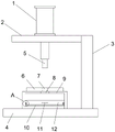
fig. 1 is a schematic structural diagram of the present invention.
Fig. 2 is a second schematic structural diagram of the present invention.
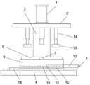
Fig. 3 is a third schematic structural diagram of the present invention.
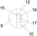
Fig. 4 is an enlarged view of a portion a of fig. 1.
Fig. 5 is a schematic structural diagram of embodiment 2 of the present invention.
In the figure: 1-hydraulic cylinder, 2-transverse plate, 3-vertical plate, 4-base, 5-punch, 6-die fixing plate, 7-die punching, 8-blanking hole, 9-fixing frame, 10-material receiving plate, 11-handle, 12-push plate, 13-pneumatic ejector rod, 14-press plate, 15-pulley, 16-chute, 17-connecting rod, 18-material receiving hopper and 19-rubber cushion.
The specific implementation mode is as follows:
the present invention will be further explained with reference to the drawings and examples.
In order to solve the above problems, the embodiment provides a plastic piece punching device, as shown in fig. 1, which includes a base 4, a vertical plate 3 is fixedly installed on the upper end surface of the right side of the base 4 through bolts, a horizontal plate 2 is arranged above the base 1, the horizontal plate 2 is fixed on the vertical plate 3 through bolts, a hydraulic cylinder 1 is installed on the upper end surface of the horizontal plate 2, the output end of the hydraulic cylinder 1 vertically penetrates through the horizontal plate 2 downwards, and a punch 5 is installed on the output end of the hydraulic cylinder 1; as shown in fig. 3, two air pressure push rods 14 are arranged on the left and right sides of the output end of the hydraulic cylinder 1, the air pressure push rods 14 are arranged in a mirror symmetry manner, the two air pressure push rods 14 are communicated on the same air path, and the controller is arranged on the air pressure ejector rod 14, the top end of the air pressure ejector rod 14 is fixed on the lower end surface of the transverse plate 2, the output end of the air pressure ejector rod 14 is fixedly provided with a pressing plate 13, the position of the air pressure ejector rod 14 does not exceed the position of the female die fixing plate 6, a fixing frame 9 is arranged on the base 4, the bottom end of the fixing frame 9 is fixed on the upper end surface of the base 4, a female die fixing plate 6 is arranged on the upper end surface of the fixing frame 9, a female die punching hole 7 is arranged in the female die fixing plate 6, the female die punching hole 7 vertically corresponds to the punch 5, the upper end surface of the fixed frame 9 is provided with a blanking hole 8 corresponding to the female die punching hole 7, and plastic piece waste materials punched by the punch 5 can fall through the blanking hole 8; a material receiving plate 10 is fixed in the fixing frame 9, the length of the material receiving plate 10 is consistent with that of the fixing frame 9, sliding grooves 16 are fixedly arranged on two inner sides of the fixing frame 9, the sliding grooves 16 are positioned above the material receiving plate 10, a push plate 12 is arranged above the material receiving plate 10, a connecting rod 17 is fixed on the side face of the head end of the push plate 12, a pulley 15 is arranged at the other end of the connecting rod 17, the pulley 15 is sleeved in the sliding grooves on the two inner sides of the fixing frame 9 in a matching manner, the push plate 12 can slide back and forth in the fixing frame 9 through the pulley 15, the bottom end face of the push plate 12 is in sliding fit with the upper end face of the material receiving plate 10, a handle 11; a receiving hopper 18 is provided at the front end side of the fixed frame 9, and the receiving hopper 18 can collect the waste material pushed out by the push plate 12 in the fixed frame 9.
When the device is used for punching a plastic part, the plastic part is placed on the female die fixing plate 6, the position to be punched is aligned to the punch 5 above, a worker starts the air pressure ejector rod 14 to enable the pressing plate 13 to move downwards and tightly press the plastic part, the plastic part is tightly pressed and fixed on the female die fixing plate 6, the hydraulic cylinder 1 is started, the hydraulic cylinder 1 enables the punch 5 to move downwards, the punching of the plastic part is completed under the coordination of the female die punching 7, the punched waste material falls onto the material receiving plate 10 through the material dropping hole 8, as the worker can enable the pushing plate 12 to slide on the material receiving plate 10 under the coordination of the pulley 15 and the chute 16, when the punched waste material is cleaned and collected, the worker can push the waste material on the material receiving plate 10 out by pushing the pushing plate 12, the pushed waste material falls into the material receiving hopper 18, the device tightly presses and fixes the plastic part on the female die fixing plate 6 through the pressing plate 14, avoid taking place to shift because of the drift when punching a hole to the working of plastics and make the error appear that punches a hole to under the effect of push pedal 12, the workman can push out the waste material and collect in collecting hopper 18, avoided the waste material to scatter the condition of not being convenient for to collect one, labour saving and time saving has improved workman's work efficiency.
Example 2 a plastic part punching apparatus according to the present embodiment will be described mainly focusing on differences from example 1.
In this embodiment, as shown in fig. 5, a rubber cushion 19 is fixed on the bottom end surface of the pressing plate 14, and under the action of the rubber cushion 19, when the pressing plate 14 presses and fastens the plastic part, a buffer layer is arranged between the pressing plate and the plastic part, so that the plastic part is not damaged by the pressing plate 14.
Example 3 a plastic part punching apparatus according to the present embodiment will be described mainly focusing on differences from example 2.
In the embodiment, a pressure sensor is arranged in the rubber cushion, the pressure sensor is electrically connected with a controller of the air pressure ejector rod 13, when the pressure plate 14 presses and fastens the plastic part, when the pressure sensor detects that the pressing force is too large, a signal is sent to the controller, the controller controls the air pressure ejector rod 13 to stop pressing after receiving the signal, the pressing force of the air pressure ejector rod 14 can be controlled through the pressure sensor, and the plastic part is prevented from being damaged due to the too large pressing force.
Example 4, a plastic part punching apparatus according to the present embodiment will be described mainly focusing on differences from example 2.
In this embodiment, blanking hole 8's through-hole size is greater than die punching 7's through-hole size, because blanking hole 8 is greater than die punching 7, the working of plastics waste material that is washed away by drift 5 can be better fall into to receiving plate 10 through blanking hole 8 on, has avoided the waste material to block up the condition in blanking hole 8, convenient to use.
The above description is only for the preferred embodiment of the present invention, and the present invention is not limited thereto, and any modification, equivalent replacement and improvement made within the spirit and principle scope of the present invention should be included within the protection scope of the present invention.
Claims (9)
1. A punching device for plastic parts comprises a base, wherein a transverse plate is arranged above the base and is connected with the base through a vertical plate, and the punching device is characterized by further comprising a hydraulic cylinder, a female die fixing plate, a fixing frame, a material cleaning mechanism and a pressing assembly, wherein the hydraulic cylinder is arranged above the transverse plate, the output end of the hydraulic cylinder is vertically downward, a punch is arranged at the output end of the hydraulic cylinder, the pressing assembly comprises an air pressure ejector rod and a pressing plate, the air pressure ejector rod is vertically downward fixed on the transverse plate, the pressing plate is fixed at the output end of the air pressure ejector rod, the fixing frame is fixed on the base, the female die fixing plate is fixed above the fixing frame, a punching hole vertically corresponding to the punch is formed in the female die fixing plate, a blanking hole corresponding to the punching hole is formed in the fixing frame, the material cleaning mechanism comprises a material receiving plate, the push pedal is established in receiving the flitch top, the spout is fixed in the interior both sides of the mount of receiving the flitch top, the pulley passes through the connecting rod to be connected with push pedal head end side, and the pulley matches the suit and is in the spout.
2. The plastic part punching device of claim 1, wherein the number of the pneumatic ejector rods is two, the pneumatic ejector rods are fixedly arranged on the left side and the right side of the output end of the hydraulic cylinder in a mirror image manner, and the fixed position of the pneumatic ejector rods does not exceed the fixed position of the female die plate.
3. The apparatus of claim 1 wherein the blanking hole is larger than the punch hole.
4. The plastic part punching device according to claim 1, further comprising a receiving hopper, wherein the receiving hopper is arranged on the front end side of the fixing frame, and the height of the receiving hopper does not exceed the height of the receiving plate.
5. The plastic part punching apparatus of claim 1, wherein the bottom surface of the pushing plate is slidably engaged with the top surface of the receiving plate.
6. The plastic part punching apparatus of claim 1, further comprising a rubber cushion secured to the bottom end face of the pressure plate.
7. The plastic part punching apparatus of claim 6, further comprising a pressure sensor mounted within the rubber cushion.
8. The apparatus of claim 1 further comprising a handle attached to the trailing face of the pusher.
9. The plastic part punching apparatus of claim 1, wherein the length of the material receiving plate and the chute corresponds to the length of the mounting bracket.
Priority Applications (1)
| Application Number | Priority Date | Filing Date | Title |
|---|---|---|---|
| CN202021109790.4U CN212707173U (en) | 2020-06-16 | 2020-06-16 | Plastic part punching device |
Applications Claiming Priority (1)
| Application Number | Priority Date | Filing Date | Title |
|---|---|---|---|
| CN202021109790.4U CN212707173U (en) | 2020-06-16 | 2020-06-16 | Plastic part punching device |
Publications (1)
| Publication Number | Publication Date |
|---|---|
| CN212707173U true CN212707173U (en) | 2021-03-16 |
Family
ID=74951523
Family Applications (1)
| Application Number | Title | Priority Date | Filing Date |
|---|---|---|---|
| CN202021109790.4U Expired - Fee Related CN212707173U (en) | 2020-06-16 | 2020-06-16 | Plastic part punching device |
Country Status (1)
| Country | Link |
|---|---|
| CN (1) | CN212707173U (en) |
Cited By (2)
| Publication number | Priority date | Publication date | Assignee | Title |
|---|---|---|---|---|
| CN113001699A (en) * | 2021-04-25 | 2021-06-22 | 杨珂腾 | Anti-adhesion device for board punching processing |
| CN114683348A (en) * | 2022-04-01 | 2022-07-01 | 安庆市康明纳包装有限公司 | Paper plastic packaging bag perforating device |
-
2020
- 2020-06-16 CN CN202021109790.4U patent/CN212707173U/en not_active Expired - Fee Related
Cited By (3)
| Publication number | Priority date | Publication date | Assignee | Title |
|---|---|---|---|---|
| CN113001699A (en) * | 2021-04-25 | 2021-06-22 | 杨珂腾 | Anti-adhesion device for board punching processing |
| CN114683348A (en) * | 2022-04-01 | 2022-07-01 | 安庆市康明纳包装有限公司 | Paper plastic packaging bag perforating device |
| CN114683348B (en) * | 2022-04-01 | 2024-02-20 | 安庆市康明纳包装有限公司 | Paper plastic packaging bag perforating device |
Similar Documents
| Publication | Publication Date | Title |
|---|---|---|
| CN212707173U (en) | Plastic part punching device | |
| CN110586753B (en) | Stamping equipment who possesses garbage collection function | |
| CN219561078U (en) | Stamping and positioning auxiliary device for automobile sheet metal part | |
| CN217166060U (en) | Punching device for large-scale high-precision sheet metal part | |
| CN217166036U (en) | Linkage stamping equipment | |
| CN214056595U (en) | Automatic positioning and die cutting production line for packing box material plates | |
| CN208840298U (en) | The punching tool of thin-wall workpiece | |
| CN210231203U (en) | Bilateral punching die | |
| CN210817129U (en) | Die feeding device | |
| CN112172239A (en) | Automatic positioning and die cutting production line for packing box material plates | |
| CN219851782U (en) | Automobile fastener mould | |
| CN218963762U (en) | Automatic processing and blanking device for tank cover | |
| CN219130496U (en) | Stamping die for automobile sheet metal | |
| CN216464910U (en) | Material punching device | |
| CN218693344U (en) | Stamping die demoulding mechanism | |
| CN218903247U (en) | Abandonment material recovery unit | |
| CN220837419U (en) | Numerical control punch with high accuracy | |
| CN214022980U (en) | Synchronous stamping device | |
| CN212238840U (en) | Punching die | |
| CN210877166U (en) | Semi-automatic aluminum sleeve riveting terminal equipment | |
| CN216369751U (en) | Snap ring stamping forming device of rigid pipe clamp | |
| CN221434612U (en) | Punching mechanism for side holes of shell forming part of card swiping machine | |
| CN220944070U (en) | Stamping die convenient for cleaning waste materials | |
| CN213617021U (en) | Unloading waste discharge device | |
| CN213350515U (en) | Mount propelling movement material mechanism of gluey pressure machine |
Legal Events
| Date | Code | Title | Description |
|---|---|---|---|
| GR01 | Patent grant | ||
| GR01 | Patent grant | ||
| CF01 | Termination of patent right due to non-payment of annual fee |
Granted publication date: 20210316 |
|
| CF01 | Termination of patent right due to non-payment of annual fee |