CN212683050U - Automatic pressure equipment machine of terminal - Google Patents
Automatic pressure equipment machine of terminal Download PDFInfo
- Publication number
- CN212683050U CN212683050U CN202021383166.3U CN202021383166U CN212683050U CN 212683050 U CN212683050 U CN 212683050U CN 202021383166 U CN202021383166 U CN 202021383166U CN 212683050 U CN212683050 U CN 212683050U
- Authority
- CN
- China
- Prior art keywords
- terminal
- press
- automatic
- fitting
- feeding mechanism
- Prior art date
- Legal status (The legal status is an assumption and is not a legal conclusion. Google has not performed a legal analysis and makes no representation as to the accuracy of the status listed.)
- Expired - Fee Related
Links
- 230000000670 limiting effect Effects 0.000 claims description 11
- 238000003825 pressing Methods 0.000 claims description 2
- 238000004519 manufacturing process Methods 0.000 abstract description 6
- 238000000034 method Methods 0.000 abstract description 5
- 238000003754 machining Methods 0.000 description 2
- 230000002411 adverse Effects 0.000 description 1
- 230000002950 deficient Effects 0.000 description 1
- 230000009466 transformation Effects 0.000 description 1
Images


Landscapes
- Press Drives And Press Lines (AREA)
Abstract
The utility model relates to an automatic terminal press-mounting machine, which comprises an equipment frame; the equipment rack is provided with a retainer for containing a material tray: the two sides of the holder containing material tray are provided with symmetrically arranged feeding vibrating trays; the discharge hole of the feeding vibration disc is connected with the linear vibration feeding mechanism; a terminal grabbing and feeding mechanism for grabbing terminals is arranged above the linear vibration feeding mechanism; one side of rectilinear vibration feed mechanism is equipped with the mould on the pressure equipment, the mould reciprocates via the pressure equipment cylinder on the pressure equipment, but the below of mould on the pressure equipment is equipped with lateral shifting's the pressure equipment lower mould that is used for loading the holder, the utility model discloses an automatic pressure equipment machine of terminal, overall structure is compact, and convenient operation can realize that the automatic permutation of terminal is expected, automatic feed material loading, the automatic holder of impressing of terminal, and whole process full automatization is accomplished, has improved the efficiency of production, has saved the whole quality that the manpower has promoted the product, accords with the development demand of enterprise.
Description
Technical Field
The utility model belongs to the automation equipment field especially relates to an automatic pressure equipment machine of terminal.
Background
In the field of machining, the terminals are often required to be pressed into corresponding workpieces, the terminals are required to be pressed into the retainer in the current production and machining, the terminals are assembled manually in the current assembly mode, so that the labor intensity of workers is improved, the production cost is high, the yield is low, the quality of products after manual assembly is uneven, defective products are easy to generate, and adverse factors are brought to further development of enterprises.
SUMMERY OF THE UTILITY MODEL
The utility model aims at overcoming the not enough of prior art and providing one kind can realize terminal automatic feeding pressure equipment, alleviate workman intensity of labour, improve the automatic pressure equipment machine of terminal of production productivity.
In order to achieve the above purpose, the utility model adopts the technical scheme that: an automatic terminal press-mounting machine comprises an equipment rack; the equipment rack is provided with a retainer for containing a material tray: the two sides of the holder containing material tray are provided with symmetrically arranged feeding vibrating trays; the discharge hole of the feeding vibration disc is connected with the linear vibration feeding mechanism; a terminal grabbing and feeding mechanism for grabbing terminals is arranged above the linear vibration feeding mechanism; and a press-fitting upper die is arranged on one side of the linear vibration feeding mechanism and moves up and down through a press-fitting cylinder, and a press-fitting lower die which can transversely move and is used for loading the retainer is arranged below the press-fitting upper die.
Furthermore, the holding frame is a rectangular frame for holding the material tray.
Further, the terminal grabbing and feeding mechanism comprises a grabbing rack, and a lifting cylinder is arranged on the grabbing rack; a piston rod of the lifting cylinder is provided with a transversely-arranged transverse cylinder; and a connecting plate is arranged on a piston rod of the transverse moving cylinder, a clamping jaw is arranged at the bottom of the connecting plate, and the clamping jaw is arranged above the linear vibration feeding mechanism.
Further, the press-fitting lower die is driven by a transverse moving cylinder to move transversely.
Further, a rotating shaft is arranged on the press-fitting lower die; the rotation shaft limiting block is provided with a limiting groove.
Furthermore, a safety grating is arranged on the equipment rack.
Furthermore, the equipment rack is also provided with an operation screen for controlling the automatic pressing machine of the terminal.
Because of above-mentioned technical scheme's application, compared with the prior art, the utility model have the following advantage:
the utility model discloses the automatic pressure equipment machine of terminal of scheme, overall structure is compact, and convenient operation can realize that the automatic permutation of terminal reason material, automatic feed material loading, the automatic holder of impressing of terminal, and whole process full automatization is accomplished, has improved the efficiency of production, has saved the whole quality that the manpower promoted the product, accords with the development demand of enterprise.
Drawings
The technical scheme of the utility model is further explained by combining the attached drawings as follows:
FIG. 1 is a schematic structural view of the present invention;
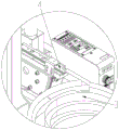
FIG. 2 is an enlarged view of portion A of FIG. 1;
FIG. 3 is an enlarged view of portion B of FIG. 1;
FIG. 4 is an enlarged view of portion C of FIG. 2;
FIG. 5 is an enlarged view of portion D of FIG. 2;
wherein: the equipment comprises an equipment rack 1, a retainer containing material disc 2, a feeding vibration disc 3, a linear vibration feeding mechanism 4, a terminal grabbing feeding mechanism 5, a press-fitting upper die 6, a press-fitting air cylinder 7, a press-fitting lower die 8, a safety grating 9, an operation screen 10, an electric cabinet 11, a retainer 12, a limiting block 30, a limiting groove 31, a grabbing rack 50, a lifting air cylinder 51, a transverse moving air cylinder 52, a connecting plate 53, a clamping jaw 54 and a lower die air cylinder 80.
Detailed Description
The present invention will be described in further detail with reference to the accompanying drawings and specific embodiments.
Referring to fig. 1-5, the present invention provides an automatic terminal press-fitting machine, which comprises an equipment frame 1; the equipment rack 1 is provided with a retainer containing material tray 2: the two sides of the retainer containing material tray 2 are provided with symmetrically arranged feeding vibrating trays 3; the discharge port of the feeding vibration disc 3 is connected with the linear vibration feeding mechanism 4, the terminals vibrated out of the feeding vibration disc 3 are automatically sorted and fed, and the terminals flow into the linear vibration feeding mechanism 4 from the corresponding discharge port; a terminal grabbing and feeding mechanism 5 for grabbing terminals is arranged above the linear vibration feeding mechanism 4; and a press-fitting upper die 6 is arranged on one side of the linear vibration feeding mechanism 4, the press-fitting upper die 6 moves up and down through a press-fitting cylinder 7, and a press-fitting lower die 8 which can move transversely and is used for loading the retainer is arranged below the press-fitting upper die 6.
As a further preferred embodiment, the holder holding tray 2 is a rectangular frame, and a plurality of holders can be placed in the holder holding tray 2, so that workers can take materials conveniently during processing.
As a further preferred embodiment, the terminal grabbing feeding mechanism 5 comprises a grabbing frame 50, and a lifting cylinder 51 is arranged on the grabbing frame 50; a piston rod of the lifting cylinder 51 is provided with a transversely-moving cylinder 52; the piston rod of the transverse moving cylinder 52 is provided with a connecting plate 53, the bottom of the connecting plate 53 is provided with a clamping jaw 54, the clamping jaw 54 is arranged above the linear vibration feeding mechanism 4, and when the linear vibration feeding mechanism is in actual use, the clamping jaw is adjusted in the transverse and vertical positions through the lifting cylinder 51 and the transverse moving cylinder 52, so that a terminal on the linear vibration feeding mechanism 4 can be conveniently grabbed and then placed into the retainer.
As a further preferred embodiment, the press-fitting lower die 8 is driven to move laterally via a lower die cylinder 80.
As a further preferred embodiment, a rotating shaft 32 is arranged on the press-fitting lower die 8, a limiting block 30 is arranged on one side of the rotating shaft, a limiting groove 31 is formed in the limiting block 30, and when the press-fitting lower die is actually used, the rotating shaft 32 is used for rotating the holder, so that different terminals are put into the holder through the clamping jaws, subsequent processing is facilitated, and the limiting groove 31 has a certain limiting effect on the holder.
As a further preferred embodiment, a safety grating 9 is further arranged on the equipment rack 1, so that a worker is protected from being accidentally injured by the press during the feeding process.
As a further preferred embodiment, the equipment rack 1 is further provided with an operation screen 10 for controlling the terminal automatic press-fitting machine, the press-fitting machine can be controlled through the operation screen 10 during operation, and the equipment rack 1 is further provided with an electric cabinet 11 for controlling the electric inside of the press-fitting machine.
When the terminal loading device is used, firstly, a worker pours the terminals into the two loading vibration discs 3 and puts the retainer 12 into the retainer containing disc 2; during work, the retainer 12 is manually placed into the two press-fitting lower dies 8, the feeding vibration disc 3 and the linear vibration feeding mechanism 4 start to work, the terminals are conveyed to the positions suitable for the terminals to grab the feeding mechanism 5, and then the terminal grabbing feeding mechanism starts to operate to grab the terminals into the retainer; then the retainer rotates by using a rotating shaft, the terminal grabbing and feeding mechanism 5 continuously grabs the terminals and puts the terminals into another position of the retainer, and the number of the terminals is adjusted according to actual products; after the terminals are placed, the press-fitting air cylinder 7 drives the press-fitting upper die 6 to press down, the terminals are pressed into the retainer 12, the equipment waits, and workers continue to perform blanking in the next process.
The utility model discloses an automatic pressure equipment machine of terminal, overall structure is compact, and convenient operation can realize that the automatic permutation of terminal reason material, automatic feed material loading, the automatic holder of impressing of terminal, and whole process full automatization is accomplished, has improved the efficiency of production, has saved the whole quality that the manpower promoted the product, accords with the development demand of enterprise.
The above is only a specific application example of the present invention, and does not constitute any limitation to the protection scope of the present invention. All the technical solutions formed by equivalent transformation or equivalent replacement fall within the protection scope of the present invention.
Claims (7)
1. The utility model provides an automatic pressure equipment machine of terminal which characterized in that: comprises an equipment frame; the equipment rack is provided with a retainer for containing a material tray: the two sides of the holder containing material tray are provided with symmetrically arranged feeding vibrating trays; the discharge hole of the feeding vibration disc is connected with the linear vibration feeding mechanism; a terminal grabbing and feeding mechanism for grabbing terminals is arranged above the linear vibration feeding mechanism; and a press-fitting upper die is arranged on one side of the linear vibration feeding mechanism and moves up and down through a press-fitting cylinder, and a press-fitting lower die which can transversely move and is used for loading the retainer is arranged below the press-fitting upper die.
2. The automatic terminal press-fitting machine according to claim 1, wherein: the holder is used for accommodating the material tray and is a rectangular frame body.
3. The automatic terminal press-fitting machine according to claim 1, wherein: the terminal grabbing and feeding mechanism comprises a grabbing rack, and a lifting cylinder is arranged on the grabbing rack; a piston rod of the lifting cylinder is provided with a transversely-arranged transverse cylinder; and a connecting plate is arranged on a piston rod of the transverse moving cylinder, a clamping jaw is arranged at the bottom of the connecting plate, and the clamping jaw is arranged above the linear vibration feeding mechanism.
4. The automatic terminal press-fitting machine according to claim 1, wherein: and the press-fitting lower die is driven by the transverse moving cylinder to move transversely.
5. The automatic terminal press-fitting machine according to claim 1, wherein: a rotating shaft is arranged on the press-fitting lower die; the rotation shaft limiting block is provided with a limiting groove.
6. The automatic terminal press-fitting machine according to claim 1, wherein: and the equipment rack is also provided with a safety grating.
7. The automatic terminal press-fitting machine according to claim 1, wherein: and the equipment rack is also provided with an operation screen for controlling the automatic pressing machine of the terminal.
Priority Applications (1)
| Application Number | Priority Date | Filing Date | Title |
|---|---|---|---|
| CN202021383166.3U CN212683050U (en) | 2020-07-14 | 2020-07-14 | Automatic pressure equipment machine of terminal |
Applications Claiming Priority (1)
| Application Number | Priority Date | Filing Date | Title |
|---|---|---|---|
| CN202021383166.3U CN212683050U (en) | 2020-07-14 | 2020-07-14 | Automatic pressure equipment machine of terminal |
Publications (1)
| Publication Number | Publication Date |
|---|---|
| CN212683050U true CN212683050U (en) | 2021-03-12 |
Family
ID=74897206
Family Applications (1)
| Application Number | Title | Priority Date | Filing Date |
|---|---|---|---|
| CN202021383166.3U Expired - Fee Related CN212683050U (en) | 2020-07-14 | 2020-07-14 | Automatic pressure equipment machine of terminal |
Country Status (1)
| Country | Link |
|---|---|
| CN (1) | CN212683050U (en) |
Cited By (1)
| Publication number | Priority date | Publication date | Assignee | Title |
|---|---|---|---|---|
| CN115246066A (en) * | 2021-10-26 | 2022-10-28 | 浙江机电职业技术学院 | Join in marriage inner and outer ring work rigging equipment of food tray bush |
-
2020
- 2020-07-14 CN CN202021383166.3U patent/CN212683050U/en not_active Expired - Fee Related
Cited By (2)
| Publication number | Priority date | Publication date | Assignee | Title |
|---|---|---|---|---|
| CN115246066A (en) * | 2021-10-26 | 2022-10-28 | 浙江机电职业技术学院 | Join in marriage inner and outer ring work rigging equipment of food tray bush |
| CN115246066B (en) * | 2021-10-26 | 2023-11-28 | 浙江机电职业技术学院 | Working assembly equipment for inner ring and outer ring of oil distribution disc bushing |
Similar Documents
| Publication | Publication Date | Title |
|---|---|---|
| CN106695096B (en) | Full-automatic welding production line for shell and stud | |
| CN210306710U (en) | Automatic punching, milling and drilling integrated equipment for communication product shell | |
| CN108620930B (en) | Full-automatic bar processing machine tool | |
| CN110920132B (en) | Automatic mold removing and assembling method suitable for diamond tool bit mold | |
| CN212683050U (en) | Automatic pressure equipment machine of terminal | |
| CN111633383A (en) | Full-automatic production line for U-shaped plates | |
| CN208131846U (en) | A kind of multi-station punch of self-feeding | |
| CN212682148U (en) | Filter toper end cover stamping forming device | |
| CN214979030U (en) | Automatic bearing press-fitting device for tail end of EPS brush motor rotor | |
| CN207522960U (en) | Even material breaks disconnected device to inserts | |
| CN213225283U (en) | Charging tray feeding device | |
| CN211307551U (en) | Automatic die removing and die assembling production line suitable for diamond tool bit die | |
| CN205852819U (en) | A kind of mechanical arm | |
| CN210497695U (en) | Wire drawing device | |
| CN210649751U (en) | Clamping equipment is used in production of hydraulic forklift scale | |
| CN111069014A (en) | Automatic splitting production line for diamond molds and cold pressed compacts | |
| CN217417374U (en) | Automatic feeding device suitable for workpieces of multiple specifications | |
| CN207103650U (en) | A kind of brazed joint feeding attachment of punch press | |
| CN212598873U (en) | Automatic shaping device for metal injection molding | |
| CN210755536U (en) | High-efficiency circular sawing machine | |
| CN210524088U (en) | Pin soldering auxiliary device for inductor | |
| CN209598045U (en) | A kind of automatic cutting system | |
| CN108788738B (en) | Permanent magnet material pressed compact processing device | |
| CN210335275U (en) | Clamping device for feeding and discharging processing | |
| CN106735328A (en) | A kind of lathe automatic loading and unloading device |
Legal Events
| Date | Code | Title | Description |
|---|---|---|---|
| GR01 | Patent grant | ||
| GR01 | Patent grant | ||
| CF01 | Termination of patent right due to non-payment of annual fee |
Granted publication date: 20210312 |
|
| CF01 | Termination of patent right due to non-payment of annual fee |