CN212679253U - Surgical equipment storage box - Google Patents
Surgical equipment storage box Download PDFInfo
- Publication number
- CN212679253U CN212679253U CN201920657201.7U CN201920657201U CN212679253U CN 212679253 U CN212679253 U CN 212679253U CN 201920657201 U CN201920657201 U CN 201920657201U CN 212679253 U CN212679253 U CN 212679253U
- Authority
- CN
- China
- Prior art keywords
- baffle
- main body
- air dryer
- plate
- infrared emitter
- Prior art date
- Legal status (The legal status is an assumption and is not a legal conclusion. Google has not performed a legal analysis and makes no representation as to the accuracy of the status listed.)
- Expired - Fee Related
Links
Images

Abstract
The utility model discloses a surgical equipment case, including main part and guard shield, the top left side of main part is connected with the bolt post, and closely laminates between main part and the bolt post, the baffle is installed to the upper end of bolt post, the bottom of baffle all is fixed with infrared emitter, and is fixed connection between baffle and the infrared emitter. This surgical equipment case can be in the same place baffle and main part buckle through the bolt post to can be with the buckle of infrared emitter firmly in the main part, and can carry out surface sterilization to the scalpel in the main part, thereby bacterium after can preventing the disinfection remains, carries out the degerming disinfection to main part inside through infrared emitter simultaneously, thereby can disinfect the operation cutter that takes out every time, but also can keep certain disinfection distance with infrared emitter and operation cutter.
Description
Technical Field
The utility model relates to a surgical equipment case specifically is a scalpel case.
Background
The scalpel is often used in the surgical operation to carry out medical operation on a patient, the scalpel body of the common scalpel is generally of an integrated structure, and therefore specific scalpel storage equipment is arranged on the scalpel body, normal operation of the surgical operation can be guaranteed, the protection of the scalpel is directly related to the health problem of the patient, the scalpel is required to be classified and disinfected for protection, operation infection of the scalpel on the patient can be improved, and therefore the scalpel storage box is required to be improved.
Scalpel case on the market does not carry out specific classification and deposits, and when the scalpel was disinfected in classification moreover, the scalpel surface was not disinfected to easy infection in the operation can aggravate patient's the state of an illness moreover, and the sterile water of scalpel does not have fine processing, thereby corrodes in the local piece of scalpel easily, but also has the problem of the inside bacterium of case.
SUMMERY OF THE UTILITY MODEL
An object of the utility model is to provide a surgical equipment case to solve the scalpel case on the market that proposes in the above-mentioned background art, do not carry out concrete classification and deposit, when the scalpel carries out classification disinfection moreover, do not carry out scalpel surface sterilization, thereby infect in the operation easily, can aggravate patient's the state of an illness moreover, the sterile water of scalpel does not have fine processing, thereby it corrodes to take place at the local piece of scalpel easily, and there is the problem of the inside bacterium of case in addition.
In order to achieve the above object, the utility model provides a following technical scheme: a surgical equipment storage box comprises a main body and a protective cover, wherein a bolt column is connected to the left side of the top end of the main body, the main body and the bolt column are tightly attached, a baffle is mounted at the upper end of the bolt column, an infrared emitter is fixed to the bottom of the baffle, the baffle and the infrared emitter are fixedly connected, a connecting rod is mounted at the right end of the baffle, the baffle and the connecting rod are tightly attached, a clamping plate is arranged at the bottom end of the left side of the infrared emitter, a rotating column is fixed to the right end of the clamping plate, a support is connected to the outer portion of the rotating column, a rail is mounted in the middle of the right side of the inner portion of the main body, the main body and the rail are in welded connection, a limiting block is fixed to the upper end and the lower end of the left side of the rail, a model plate is connected to the, and the central line intersects between guard shield and the air dryer, the bottom mounting of air dryer has the sliding plate, the inside left side bottom mounting of main part has the water pump, and closely laminate between main part and the water pump, the left side of water pump is connected with the pipeline, both ends are fixed with the movable groove about the left side of pipeline, and the right-hand member in movable groove is connected with the filter screen shower nozzle.
Preferably, the main body is parallel to the baffle, the main body is in a snap structure through the bolt column and the baffle, and the bolt column is in threaded connection with the baffle.
Preferably, the main body and the bracket are fixedly connected, and the bracket is configured to have an engagement structure with the mold plate through the rotation column.
Preferably, the limit block is tightly attached to the model plate, and the track is of a lifting structure through the limit block and the model plate.
Preferably, the air dryer is fixedly connected with the sliding plate, and the main body is in a sliding structure through the air dryer and the sliding plate.
Preferably, be welded connection between water pump and the pipeline, and the water pump constitutes to be dismantled the structure through constituting between filter screen shower nozzle and the activity groove to closely laminate between filter screen shower nozzle and the activity groove.
Compared with the prior art, the beneficial effects of the utility model are as follows:
1. the utility model discloses a main part constitutes buckle structure through between bolt post and the baffle, and closely laminate between bolt post and the baffle, and constitute block structure through between column of revolution and the template, can buckle baffle and main part together through the bolt post, thereby can be with the firm buckle of infrared emitter in the main part, and can carry out surface sterilization to the scalpel in the main part, thereby can prevent the bacterium after the disinfection and remain, simultaneously carry out degerming disinfection to the main part inside through infrared emitter, thereby can carry out disinfection and sterilization to the surgical knife that takes out each time, and can also keep certain disinfection and sterilization distance with infrared emitter and surgical knife, through the motion of buckle board between support and column of revolution, thereby can block buckle board on the template, through the function of buckle board is exactly for preventing that the surgical instrument from taking place to drop in rotatory process, the operation tool is arranged on the clamping plate for the first time, so that the operation tool is disinfected by disinfectant water, the rotary clamping on the model plate is used for carrying out secondary arrangement disinfection and sterilization on the disinfected operation tool, the filter screen spray head on the movable groove is disassembled, so that the upper and lower movable spaces of the clamping plate can be enlarged, the movable interference between two sides can be prevented, and if the falling phenomenon of the operation tool occurs, the two layers can be mutually replaced, the bolt column is screwed, so that the baffle can be opened, the surface arrangement of the model plate can be carried out, the infrared ray disinfection and sterilization are convenient, the operation tool can be directly clamped on the model plate, so that the clamping plate can be arranged in a new round in a layered mode, the disinfected operation tool is rotatably clamped on the model plate, not only the other surface is disinfected, but also the surface of the operation tool can be simultaneously classified in a layered mode, the operation knife is characterized by comprising a model plate, a knife holder, a knife blade, a knife;
2. the utility model discloses the track is through constituting elevation structure between stopper and the model plate, and the main part constitutes sliding construction through between air dryer and the sliding plate, can take out the surgical tool on the model plate and thus in the main part through going up and down, thereby facilitate the disinfection treatment of bottom layer, through the orbital motion in the main part of model plate and stopper, thereby can carry out the up-and-down motion of model plate, consequently can carry out the surface sterilization of the infrared emitter with the scalpel on different layers, and facilitate the extraction of the surgical tool on the track by the staff, thereby can contact the surgical tool on different layers with the infrared emitter, and can drive the connecting rod through the baffle, thereby conveniently change the model plate on the track, through the sliding between main part and guard shield of air dryer and sliding plate, thereby can carry out the pull-pull treatment to the air dryer in the main part, the air dryer is started, so that the surgical knife in the template can be dried, the surface of the surgical knife can be prevented from being provided with the sterilizing liquid, and the other half of the main body can be kept dry, so that the layered sterilized surgical knife can be comprehensively classified and stored;
3. the utility model discloses the water pump passes through the filter screen shower nozzle and constitutes to dismantle the structure between the activity groove, and closely laminate between filter screen shower nozzle and the activity groove, just can dismantle the pipeline through activity groove in its surface activity, thereby can transmit disinfectant liquid through the pipeline through starting the water pump, thereby can spray the operation cutter on the buckle board through the filter screen shower nozzle repeatedly, and can also disinfect to upper and lower two-layer buckle board, thereby can prevent the disinfection of operation sword and omit the phenomenon, and through the slip of activity groove on the pipeline, thereby can dismantle the filter screen shower nozzle and handle, consequently, make things convenient for the buckle board to control the block and remove, thereby can carry out the layered processing disinfection to the operation cutter.
Drawings
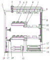
FIG. 1 is a schematic view of the internal structure of the present invention;
FIG. 2 is a schematic top view of the present invention;
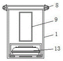
fig. 3 is a schematic view of the structure of the right side of the present invention.
In the figure: 1. a main body; 2. a bolt column; 3. a baffle plate; 4. an infrared emitter; 5. a buckle plate; 6. a support; 7. a spin column; 8. a connecting rod; 9. a track; 10. a limiting block; 11. a mold plate; 12. a shield; 13. an air dryer; 14. a sliding plate; 15. a water pump; 16. a filter screen spray head; 17. a movable groove; 18. a pipeline.
Detailed Description
The technical solutions in the embodiments of the present invention will be described clearly and completely with reference to the accompanying drawings in the embodiments of the present invention, and it is obvious that the described embodiments are only some embodiments of the present invention, not all embodiments. Based on the embodiments in the present invention, all other embodiments obtained by a person skilled in the art without creative work belong to the protection scope of the present invention.
Referring to fig. 1, fig. 2 and fig. 3, the present invention provides a technical solution: a surgical equipment storage box comprises a main body 1 and a shield 12, wherein a bolt column 2 is connected to the left side of the top end of the main body 1, the main body 1 is tightly attached to the bolt column 2, a baffle 3 is installed at the upper end of the bolt column 2, the main body 1 is parallel to the baffle 3, a buckle structure is formed between the bolt column 2 and the baffle 3 of the main body 1, the bolt column 2 is in threaded connection with the baffle 3, the baffle 3 and the main body 1 can be buckled together through the bolt column 2, an infrared emitter 4 can be firmly buckled on the main body 1, a surgical knife in the main body 1 can be subjected to surface sterilization, bacteria residue after sterilization can be prevented, the inside of the main body 1 can be subjected to sterilization through the infrared emitter 4, surgical knife taken out every time can be sterilized, and the infrared emitter 4 and the surgical knife can be kept at a certain sterilization distance, the bottom of the baffle 3 is fixed with an infrared emitter 4. The baffle 3 is fixedly connected with the infrared emitter 4, the connecting rod 8 is installed at the right end of the baffle 3, the baffle 3 is tightly attached to the connecting rod 8, the bottom end of the left side of the infrared emitter 4 is provided with the buckling plate 5, the right end of the buckling plate 5 is fixedly provided with the rotating column 7, the outer part of the rotating column 7 is connected with the support 6, the main body 1 is fixedly connected with the support 6, the support 6 is in a clamping structure through the rotating column 7 and the model plate 11, the buckling plate 5 can be clamped on the model plate 11 through the movement of the buckling plate 5 between the support 6 and the rotating column 7, the clamping plate 5 has the function of preventing the surgical tool from falling off in the rotating process, the surgical tool is arranged on the buckling plate 5 for the first time, and is disinfected by disinfectant water, so that the rotating clamping on the model plate 11 is used for secondary arrangement and disinfection of the surgical tool after disinfection, by disassembling the filter screen nozzle 16 on the movable groove 17, the up-and-down movement space of the buckle plate 5 can be enlarged, and simultaneously the occurrence of the movement interference between the two sides can be prevented, and if the falling phenomenon of the operation tool occurs, the two layers can be replaced with each other, and the baffle 3 can be opened by screwing the bolt column 2, so that the surface arrangement of the model plate 11 can be carried out, thereby facilitating the infrared sterilization, and the operation tool can be directly clamped on the model plate 11, thereby carrying out the new round of layered arrangement of the buckle plate 5, and the operation tool after the sterilization can be rotationally clamped on the model plate 11, thereby carrying out the infrared sterilization, the sterilization work not only can be carried out on the other side, but also can be carried out the surface classification of the operation tool after the sterilization, and can clamp different kinds of tools on the model plate 11, thereby the classified disinfection of the scalpel can be carried out according to the operation requirement, and the middle part of the right side in the main body 1 is provided with a track 9; the main body 1 is welded with the track 9, the upper end and the lower end of the left side of the track 9 are fixed with the limiting blocks 10, the inner sides of the limiting blocks 10 are connected with the model plate 11, the limiting blocks 10 are tightly attached to the model plate 11, the track 9 forms a lifting structure through the limiting blocks 10 and the model plate 11, surgical tools on the model plate 11 can be taken out of the main body 1 through lifting, thereby facilitating the disinfection treatment of the bottom layer and the lower layer, the track 9 moves on the main body 1 through the model plate 11 and the limiting blocks 10, thereby the model plate 11 can move up and down, therefore, surgical knives on different layers can be sterilized on the surface of the infrared emitter 4, and the surgical tools on the track 9 can be conveniently extracted by workers, thereby surgical knives on different layers can be contacted with the infrared emitter 4, and the connecting rod 8 can be driven by the baffle 3, thereby conveniently changing the model plate 11 on the track 9, the shield 12 is arranged at the bottom end of the right side in the main body 1, the inner side of the shield 12 is connected with the air dryer 13, the center line between the shield 12 and the air dryer 13 is crossed, the bottom end of the air dryer 13 is fixed with the sliding plate 14, the air dryer 13 is fixedly connected with the sliding plate 14, the main body 1 is of a sliding structure through the air dryer 13 and the sliding plate 14, through the sliding of the air dryer 13 and the sliding plate 14 between the main body 1 and the shield 12, the air dryer 13 in the main body 1 can be drawn and pulled, and through starting the air dryer 13, the surgical knife in the model plate 11 can be dried, meanwhile, the surface can be prevented from having the sterilizing liquid, and the other half of the main body 1 can be kept dry, thereby the knife after the layered sterilizing treatment can be comprehensively classified and stored, the bottom end of the left side of the inside of the main body 1 is fixed with a water pump 15, the main body 1 is tightly attached to the water pump 15, the left side of the water pump 15 is connected with a pipeline 18, the upper end and the lower end of the left side of the pipeline 18 are fixed with movable grooves 17, the right end of the movable groove 17 is connected with a filter screen spray head 16, the water pump 15 is welded with the pipeline 18, the water pump 15 forms a disassembly structure through the filter screen spray head 16 and the movable grooves 17, the filter screen spray head 16 is tightly attached to the movable grooves 17, the water pump 15 is started so as to transmit the disinfection liquid through the pipeline 18, so that the surgical tools on the buckle plate 5 can be repeatedly sprayed through the filter screen spray head 16, the upper and lower layers of buckle plates 5 can be disinfected, thereby the phenomenon of surgical knife disinfection omission can be prevented, the sliding of the movable grooves 17 on the pipeline 18 can be disassembled through the movable, therefore, the filter screen spray head 16 can be detached for treatment, so that the clamping plate 5 can be conveniently clamped and moved left and right, and the surgical knife can be treated and disinfected in a layered manner.
The working principle is as follows: as for the surgical equipment storage box, the infrared emitter 4 of the HIR19-21C-L11TR8 can sterilize the surface of the surgical tool, the clamping plate 5 and the model plate 11 of the main body 1 can be used for layering the surgical tool on the left side and the right side, the surgical tool on the model plate 11 can be conveniently lifted up and down to extract the surgical tool, the water pump 15 is started to transmit the sterilizing liquid through the pipeline 18, the surgical tool on the clamping plate 5 can be repeatedly sprayed through the filter screen spray head 16, the clamping plates 5 on the upper layer and the lower layer can be sterilized, the phenomenon of omission of the sterilization of the surgical knife can be prevented, the movable groove 17 slides on the pipeline 18, the pipeline 18 can be detached only through the surface movement of the movable groove 17, the filter screen spray head 16 can be detached for processing, and the clamping plate 5 can be conveniently clamped and moved left and right, so that the surgical knife can be disinfected in a layered manner, the air dryer 13 in the main body 1 can be drawn and pulled by sliding the air dryer 13 and the sliding plate 14 between the main body 1 and the shield 12, the surgical knife in the template 11 can be dried by starting the air dryer 13, meanwhile, the surface can be prevented from being provided with disinfectant liquid, the other half of the main body 1 can be kept dry, the knife after the layered disinfection treatment can be stored in a comprehensive and classified manner, the clamping plate 5 can be clamped on the template 11 through the rotating column 7 through the movement of the clamping plate 5 between the support 6 and the rotating column 7, the surgical knife can be directly clamped and placed on the template 11, the clamping plate 5 has the function of preventing the surgical knife from falling off in the rotating process, and the surgical knife is placed on the clamping plate 5 for the first time, thereby sterilizing the surgical instruments with sterilizing water, so that the rotary clamping on the model plate 11 is to perform secondary arrangement sterilization on the sterilized surgical instruments, the movable space above and below the clamping plate 5 can be enlarged by disassembling the filter screen spray head 16 on the movable groove 17, and simultaneously the movable interference between the two sides can be prevented, and if the falling-off phenomenon of the surgical instruments occurs, the two layers can be mutually replaced, and the surface arrangement of the model plate 11 can be performed by opening the baffle plate 3 by screwing the bolt column 2, thereby facilitating the infrared sterilization, thereby performing a new round of layered arrangement on the clamping plate 5, rotatably clamping the sterilized surgical instruments on the model plate 11, thereby performing the infrared sterilization, sterilizing not only the other surface, but also performing surface classification on the surgical instruments, and different kinds of knives can be clamped on the model plate 11, so that the classified disinfection of the scalpels can be carried out according to the operation requirement, the baffle plate 3 and the main body 1 can be clamped together through the bolt column 2, so that the infrared emitter 4 can be firmly clamped on the main body 1, and the surface of the scalpels in the main body 1 can be sterilized, so that the residual bacteria after the disinfection can be prevented, meanwhile, the interior of the main body 1 can be sterilized through the infrared emitter 4, so that the surgical knives taken out every time can be sterilized, and the infrared emitter 4 and the surgical knives can be kept at a certain sterilization distance, the sterilized water sprayed at the end can be blocked through the clamping plate 5, and the infrared disinfection can be carried out on the scalpels 11 through the left and right clamping, so that the sterilized water can be prevented from splashing on the infrared emitter 4, through the motion of model board 11 and stopper 10 track 9 on main part 1, thereby can carry out oscilaltion motion with model board 11, consequently can carry out 4 surface sterilization of infrared emitter with the scalpel on the aspect of difference, and make things convenient for the staff to draw surgical tool on track 9, thereby can all contact with infrared emitter 4 to the surgical knife utensil of different aspect, and can drive connecting rod 8 through baffle 3, thereby conveniently change model board 11 on track 9, this is the theory of operation of surgical equipment case.
Although embodiments of the present invention have been shown and described, it will be appreciated by those skilled in the art that changes, modifications, substitutions and alterations can be made in these embodiments without departing from the principles and spirit of the invention, the scope of which is defined in the appended claims and their equivalents.
Claims (6)
1. A surgical instrument storage box comprising a main body (1) and a hood (12), characterized in that: the bolt column (2) is connected to the left side of the top end of the main body (1), the main body (1) and the bolt column (2) are tightly attached, the baffle (3) is installed at the upper end of the bolt column (2), the infrared emitter (4) is fixed to the bottom of the baffle (3), the baffle (3) and the infrared emitter (4) are fixedly connected, the connecting rod (8) is installed at the right end of the baffle (3), the baffle (3) and the connecting rod (8) are tightly attached, the buckle plate (5) is arranged at the bottom end of the left side of the infrared emitter (4), the rotating column (7) is fixed to the right end of the buckle plate (5), the support (6) is connected to the outer portion of the rotating column (7), the track (9) is installed in the middle portion of the inner right side of the main body (1), and the main body (1) and the track (9) are connected, the utility model discloses a building air conditioner, including track (9), stopper (10), air dryer (13), air dryer (12), slide plate (18), water pump (15), and closely laminate between main part (1) and water pump (15), the left side of water pump (15) is connected with pipeline (18), both ends are fixed with movable groove (17) about the left side of pipeline (18), and the right-hand member of movable groove (17) is connected with filter screen shower nozzle (16), and the inboard of stopper (10) is connected with model board (11), guard shield (12) set up in the inside right side bottom of main part (1), the inboard of guard shield (12) is connected with air dryer (13), and the central line is crossing between guard shield (12) and air dryer (13), the bottom mounting of air dryer (13) has slide plate (14), the inside left side bottom mounting of main.
2. A surgical instrument storage case according to claim 1, wherein: the main body (1) is parallel to the baffle (3), the main body (1) is in a buckling structure through the bolt column (2) and the baffle (3), and the bolt column (2) is in threaded connection with the baffle (3).
3. A surgical instrument storage case according to claim 1, wherein: the main body (1) and the bracket (6) are fixedly connected, and the bracket (6) is in a clamping structure with the model plate (11) through the rotating column (7).
4. A surgical instrument storage case according to claim 1, wherein: the limiting blocks (10) are tightly attached to the model plates (11), and the rails (9) are in a lifting structure through the limiting blocks (10) and the model plates (11).
5. A surgical instrument storage case according to claim 1, wherein: the air dryer (13) is fixedly connected with the sliding plate (14), and the main body (1) forms a sliding structure through the air dryer (13) and the sliding plate (14).
6. A surgical instrument storage case according to claim 1, wherein: for welded connection between water pump (15) and pipeline (18), and constitute between water pump (15) and activity groove (17) through filter screen shower nozzle (16) and dismantle the structure to closely laminate between filter screen shower nozzle (16) and the activity groove (17).
Priority Applications (1)
| Application Number | Priority Date | Filing Date | Title |
|---|---|---|---|
| CN201920657201.7U CN212679253U (en) | 2019-05-09 | 2019-05-09 | Surgical equipment storage box |
Applications Claiming Priority (1)
| Application Number | Priority Date | Filing Date | Title |
|---|---|---|---|
| CN201920657201.7U CN212679253U (en) | 2019-05-09 | 2019-05-09 | Surgical equipment storage box |
Publications (1)
| Publication Number | Publication Date |
|---|---|
| CN212679253U true CN212679253U (en) | 2021-03-12 |
Family
ID=74891983
Family Applications (1)
| Application Number | Title | Priority Date | Filing Date |
|---|---|---|---|
| CN201920657201.7U Expired - Fee Related CN212679253U (en) | 2019-05-09 | 2019-05-09 | Surgical equipment storage box |
Country Status (1)
| Country | Link |
|---|---|
| CN (1) | CN212679253U (en) |
Cited By (1)
| Publication number | Priority date | Publication date | Assignee | Title |
|---|---|---|---|---|
| CN113476149A (en) * | 2021-07-20 | 2021-10-08 | 李晶晶 | Surgical instrument table convenient for taking surgical instruments |
-
2019
- 2019-05-09 CN CN201920657201.7U patent/CN212679253U/en not_active Expired - Fee Related
Cited By (1)
| Publication number | Priority date | Publication date | Assignee | Title |
|---|---|---|---|---|
| CN113476149A (en) * | 2021-07-20 | 2021-10-08 | 李晶晶 | Surgical instrument table convenient for taking surgical instruments |
Similar Documents
| Publication | Publication Date | Title |
|---|---|---|
| CN108273081B (en) | Medical scalpel disinfection and sterilization method | |
| CN107224328A (en) | A kind of medical apparatus storing compartment with sterilizing function | |
| CN112890984A (en) | Surgical medical instrument disinfection treatment method | |
| CN212679253U (en) | Surgical equipment storage box | |
| CN112317388A (en) | Cleaning equipment for ear-nose-throat department surgical instruments | |
| CN115815183A (en) | Many functional type medical instrument belt cleaning device | |
| CN112402662A (en) | Orthopedic scalpel disinfection device and using method thereof | |
| CN205215778U (en) | Laboratory cleaning and disinfection device | |
| CN211796859U (en) | Portable emergency department who takes mechanism of disinfecting uses medical shallow | |
| CN211410287U (en) | Cleaning and sterilizing equipment for clinical operation instruments of obstetrics and gynecology department | |
| CN113797993B (en) | Sample drawing operation table for tissue pathological diagnosis | |
| CN211835512U (en) | Air sterilizing device for preventing infectious disease diffusion in hospital | |
| CN114653654A (en) | Medical science nursing is with degassing unit that disinfects | |
| CN210330723U (en) | Electric knife capable of cleaning wound for laparoscopic surgery | |
| CN210019684U (en) | Multi-functional disinfection platform of bone surgery | |
| CN213941563U (en) | Multi-functional disinfection platform of bone surgery | |
| CN209187333U (en) | A kind of purification storage vehicle for acupuncture treatment tool | |
| CN207025393U (en) | A kind of Multifunctional test platform for medical clinical laboratory | |
| CN204840008U (en) | Liver disease treatment is with preventing that cross infection diagnoses bed | |
| CN217286064U (en) | Auxiliary instrument for surgical operation | |
| CN218356403U (en) | Surgical nursing flusher | |
| CN213759191U (en) | Dressing change equipment for major surgery nursing | |
| CN213993734U (en) | Operating room instrument is placed and recovery unit | |
| CN209519031U (en) | A kind of debridement nursing frame | |
| CN211633585U (en) | Hepatobiliary surgery is with operation frame |
Legal Events
| Date | Code | Title | Description |
|---|---|---|---|
| GR01 | Patent grant | ||
| GR01 | Patent grant | ||
| CF01 | Termination of patent right due to non-payment of annual fee | ||
| CF01 | Termination of patent right due to non-payment of annual fee |
Granted publication date: 20210312 |