CN212614547U - Take elevating system's brill anchor platform - Google Patents
Take elevating system's brill anchor platform Download PDFInfo
- Publication number
- CN212614547U CN212614547U CN202021251815.4U CN202021251815U CN212614547U CN 212614547 U CN212614547 U CN 212614547U CN 202021251815 U CN202021251815 U CN 202021251815U CN 212614547 U CN212614547 U CN 212614547U
- Authority
- CN
- China
- Prior art keywords
- platform
- oil cylinder
- seat
- main body
- connecting seat
- Prior art date
- Legal status (The legal status is an assumption and is not a legal conclusion. Google has not performed a legal analysis and makes no representation as to the accuracy of the status listed.)
- Active
Links
Images


Landscapes
- Earth Drilling (AREA)
Abstract
The utility model discloses a take elevating system's brill anchor platform, including the work platform main part, the lift connecting seat, the overhanging cantilever crane of platform main part, flexible arm, operation platform and landing leg, the lift connecting seat sets up in the head end of work platform main part, the lift connecting seat passes through elevating system and is connected with the main platform of the rail suspension in the tunnel, flexible arm sets up in the head end of work platform main part, flexible arm is connected with the work platform main part through flexible hydro-cylinder, the overhanging cantilever crane of platform main part sets up in the head end of work platform main part, flexible arm passes through guiding mechanism and is connected with the overhanging cantilever crane of platform main part, the landing leg sets up in the head end bottom of flexible arm, the head end of flexible arm is provided with the mount pad; the utility model discloses a hoist mechanism "hoist and mount" can rise and descend along with elevating system goes up lift cylinder's flexible on the suspension rail main platform, also can deflect left or right under the drive of lifing arm steering cylinder, satisfies full section operation needs.
Description
Technical Field
The utility model relates to a tunnelling machine technical field especially relates to a take elevating system's brill anchor platform.
Background
At present, in the roadway excavation construction process of China, crawler belt or tire type traveling equipment is generally adopted, the roadway excavation equipment of the type travels on the ground, and due to the influence of the roadway section, the equipment volume and the like, in the roadway excavation process, different equipment needs to be replaced according to different construction procedures, namely the equipment in the previous procedure needs to be withdrawn, the equipment in the process enters, namely the equipment needs to be staggered in a narrow roadway, the production efficiency is seriously influenced, and potential safety hazards exist.
Disclosure of Invention
The utility model aims at providing a drilling anchor platform with a lifting mechanism, which solves the problems existing in the prior art, the platform structure is connected with a suspension rail main platform through the lifting mechanism, the 'vehicle-staggering' in a roadway can be avoided, the production efficiency is high, the potential safety hazard is small, a rock drilling machine or a roof bolter can be arranged at the front end of the platform, and a head-on blast hole or a top anchor rod and anchor cable hole can be synchronously drilled; when boring group portion anchor rod hole, crisscross anchor rod hole that can bore group portion behind the roofbolter that stretches out, consequently the utility model discloses can realize carrying out operations such as full sectional rock drilling or beating stock anchor rope hole to the tunnel.
In order to achieve the above object, the utility model provides a following scheme:
the utility model provides a drill anchor platform with a lifting mechanism, which comprises a working platform main body, a lifting connecting seat, an overhanging arm support of the platform main body, a telescopic arm, an operating platform and a supporting leg, wherein the lifting connecting seat is arranged at the head end of the working platform main body, the lifting connecting seat is connected with a suspended rail main platform in a roadway through the lifting mechanism, the telescopic arm is arranged at the head end of the working platform main body, the telescopic arm is connected with the working platform main body through a telescopic oil cylinder, the telescopic oil cylinder controls the telescopic arm to be telescopic, the overhanging arm support of the platform main body is arranged at the head end of the working platform main body, the telescopic arm is connected with the overhanging arm support of the platform main body through a guide mechanism, the operating platform is arranged at the top of the telescopic arm, the supporting leg is arranged at the bottom of the head end of the telescopic arm, the, the mounting seat is used for mounting an anchor rod drilling machine or a rock drilling machine;
the lifting mechanism comprises a main platform connecting seat, a deflection seat, an upper arm, a lower arm, a lifting oil cylinder, a drilling anchor platform steering oil cylinder and a lifting mechanism deflection oil cylinder, the main platform connecting base is hinged with the suspension rail main platform through a pin shaft and is also connected with the suspension rail main platform through a lifting mechanism deflection oil cylinder, the eccentric seat is hinged with the main platform connecting seat through a pin shaft, two sides of the eccentric seat are respectively connected with the lifting connecting seat through a lifting mechanism deflection oil cylinder which is transversely arranged, the main platform connecting seat is connected with the top end of the eccentric seat through the upper arm, the two ends of the upper arm are respectively hinged with the main platform connecting seat and the eccentric seat, the bottom ends of the main platform connecting seat and the eccentric seat are connected through the lower arm, and the two ends of the lower arm are respectively hinged with the main platform connecting seat and the eccentric seat; the two sides of the bottom of the main platform connecting seat are respectively hinged with one end of a lifting oil cylinder, and the other ends of the two lifting oil cylinders are respectively hinged with the two sides of the upper arm.
Preferably, the cylinder body end of the telescopic oil cylinder is hinged to the working platform main body, and the piston rod end of the telescopic oil cylinder is hinged to the telescopic arm.
Preferably, the guide mechanism comprises a guide rail and a guide rail seat, the guide rail is arranged on the telescopic boom, the guide rail seat is arranged on the cantilever crane of the platform main body, and the guide rail is connected in the guide rail seat in a sliding manner.
Preferably, the telescopic arms are provided with at least one set.
Preferably, operation platform with the flexible arm is detachable connects, operation platform's both sides still are provided with the guardrail of dismantling the connection, one side of operation platform is provided with the cat ladder that supplies operating personnel to go up and down.
Preferably, the operation platform is a folding type platform and comprises a first platform, a second platform, a first turning plate and a second turning plate, the first end of the first platform is connected with the first turning plate through a hinge, the second end of the second platform is connected with the second turning plate through a hinge, the first platform is connected with the second platform through a hinge, and the first turning plate is connected with the second turning plate through a hinge.
Preferably, the supporting leg comprises a supporting leg main body, a supporting leg stretching oil cylinder, a foot grab connecting rod and a supporting leg foot grab, the top end of the supporting leg main body is hinged with the telescopic arm, one side of the supporting leg main body is connected with the head end of the cantilever crane of the platform main body through a supporting leg overturning oil cylinder, and two ends of the supporting leg overturning oil cylinder are respectively hinged with the supporting leg main body and the cantilever crane of the platform main body;
the bottom both sides of landing leg main part articulate respectively and are connected with a landing leg foot and grab, landing leg supporting foot receipts and opens the hydro-cylinder inlay in the landing leg main part, the bottom of the piston rod of landing leg supporting foot receipts and opens the hydro-cylinder is articulated to be connected with two the connecting rod is grabbed to the foot, two the bottom of connecting rod is grabbed to the foot articulates respectively and is connected one the landing leg foot is grabbed.
Preferably, the mounting seat is connected with a connecting seat, one end of the connecting seat is connected with the mounting seat, and the other end of the connecting seat is connected with one end of the spiral swinging oil cylinder;
the connecting seat is connected with the cantilever crane of the platform main body through a drill boom overturning oil cylinder, one end of the drill boom overturning oil cylinder is hinged to the top of the cantilever crane of the platform main body, and the other end of the drill boom overturning oil cylinder is hinged to the top of the connecting seat; the other end of the spiral swing oil cylinder is connected with the anchor rod swing frame, two swing angle oil cylinders are respectively arranged on two sides of the anchor rod swing frame, one end of each swing angle oil cylinder is hinged to the anchor rod swing frame, the other end of each swing angle oil cylinder is hinged to two sides of the anchor rod swing seat, one side of the anchor rod swing seat is connected with the compensation oil cylinder, and the compensation oil cylinder is provided with an anchor rod drilling machine propulsion assembly or a rock drilling machine propulsion assembly.
The utility model discloses following beneficial technological effect has been gained for prior art:
1. the utility model provides a take elevating system's brill anchor platform, this kind of brill anchor platform pass through elevating system "hoist and mount" on the rail hanging main platform, can rise and descend along with elevating system goes up lift cylinder's flexible, also can turn to left or right deflection under the drive of hydro-cylinder at the lifing arm, satisfy full section operation needs.
2. The drilling and anchoring platform with the lifting mechanism provided by the utility model can not make a mistake in the roadway, has high production efficiency and small potential safety hazard, and can be provided with a rock drilling machine or a jumbolter at the front end of the platform and can synchronously drill a head-on blast hole or a top anchor rod and anchor cable hole; when boring group portion anchor rod hole, crisscross anchor rod hole that can bore group portion behind the roofbolter that stretches out, consequently the utility model discloses can realize carrying out operations such as full sectional rock drilling or beating stock anchor rope hole to the tunnel.
Drawings
In order to more clearly illustrate the embodiments of the present invention or the technical solutions in the prior art, the drawings required to be used in the embodiments will be briefly described below, and it is obvious that the drawings in the following description are only some embodiments of the present invention, and for those skilled in the art, other drawings can be obtained according to these drawings without creative efforts.
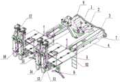
Fig. 1 is a schematic perspective view of a drill anchor platform with a lifting mechanism of the present invention;
FIG. 2 is a top view of FIG. 1;
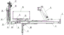
FIG. 3 is a front view of FIG. 1;
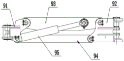
fig. 4 is a schematic view of a forward structure of the lifting mechanism of the present invention;
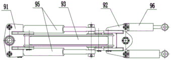
fig. 5 is a schematic view of a downward structure of the lifting mechanism of the present invention;
fig. 6 is a schematic diagram of a forward structure of the operation platform of the present invention;
FIG. 7 is a side view of FIG. 6;
FIG. 8 is a top view of FIG. 6;
fig. 9 is a schematic view of a forward structure of a leg of the present invention;
fig. 10 is a schematic side view of a support leg according to the present invention;
in the figure: 1-a working platform body, 2-a lifting connecting seat, 3-a platform body cantilever crane, 4-a telescopic arm, 5-an operating platform, 51-a guardrail, 52-a ladder stand, 53-a platform I, 54-a platform II, 55-a turning plate I, 56-a turning plate II, 6-a supporting leg, 61-a supporting leg body, 62-a supporting leg retracting oil cylinder, 63-a foot grabbing connecting rod, 64-a supporting leg foot grabbing, 65-a supporting leg overturning oil cylinder, 7-a telescopic oil cylinder, 8-a mounting seat, 9-a lifting mechanism, 91-a main platform connecting seat, 92-a deflection seat, 93-an upper arm, 94-a lower arm, 95-a lifting oil cylinder, 96-a drill anchor platform steering oil cylinder, 10-a connecting seat, 11-a spiral swinging oil cylinder, 12-a drill arm overturning oil cylinder, 12-a drill arm, 13-anchor rod swing frame, 14-swing angle oil cylinder, 15-anchor rod swing seat, 16-compensation oil cylinder and 17-anchor rod drilling machine propulsion assembly.
Detailed Description
The technical solutions in the embodiments of the present invention will be described clearly and completely with reference to the accompanying drawings in the embodiments of the present invention, and it is obvious that the described embodiments are only some embodiments of the present invention, not all embodiments. Based on the embodiments in the present invention, all other embodiments obtained by a person skilled in the art without creative work belong to the protection scope of the present invention.
The utility model aims at providing a take elevating system's brill anchor platform to solve the problem that prior art exists.
In order to make the above objects, features and advantages of the present invention more comprehensible, the present invention is described in detail with reference to the accompanying drawings and the detailed description.
The drilling and anchoring platform with the lifting mechanism in the embodiment is shown in fig. 1-3, and comprises a working platform main body 1, a lifting connecting seat 2, a platform main body overhanging arm support 3, a telescopic arm 4, an operating platform 5 and a supporting leg 6, wherein the lifting connecting seat 2 is arranged at the head end of the working platform main body 1, the lifting connecting seat 2 is connected with a suspended rail main platform (not shown in the figure) in a roadway through a lifting mechanism 9, the telescopic arm 4 is arranged at the head end of the working platform main body 1, the telescopic arm 4 is connected with the working platform main body 1 through a telescopic oil cylinder 7, the telescopic oil cylinder 7 controls the telescopic arm 4 to stretch, the platform main body overhanging arm support 3 is arranged at the head end of the working platform main body 1, the telescopic arm 4 is connected with the platform main body overhanging arm support 3 through a guide mechanism, the operating platform 5 is arranged at the top of, the head end of flexible arm 4 is provided with mount pad 8, and mount pad 8 is used for installing roofbolter or rock drill.
As shown in fig. 4-5, the lifting mechanism 9 includes a main platform connecting seat 91, a deflecting seat 92, an upper arm 93, a lower arm 94, a lifting cylinder 95, a drill anchor platform steering cylinder 96 and a lifting mechanism deflecting cylinder, the main platform connecting seat 91 is hinged to the suspended rail main platform through a pin, the main platform connecting seat 91 is further connected to the suspended rail main platform through a lifting mechanism deflecting cylinder (not shown in the figure), the deflecting seat 92 is hinged to the main platform connecting seat 91 through a pin, two sides of the deflecting seat 92 are further connected to the lifting connecting seat 2 through a transversely arranged lifting mechanism deflecting cylinder, two ends of the lifting mechanism deflecting cylinder are hinged to the deflecting seat 92 and the lifting connecting seat 2, top ends of the main platform connecting seat 91 and the deflecting seat 92 are connected through the upper arm 93, two ends of the upper arm 93 are hinged to the main platform connecting seat 91 and the deflecting seat 92, bottom ends of the main platform connecting seat 91 and the deflecting seat 92 are connected through the, the two ends of the lower arm 94 are respectively hinged with the main platform connecting seat 91 and the deflection seat 92; two sides of the bottom of the main platform connecting seat 91 are respectively hinged with one end of a lifting oil cylinder 95, and the other ends of the two lifting oil cylinders 95 are respectively hinged with two sides of the upper arm 93; during operation, under the driving of the lifting oil cylinder 95, the lifting mechanism steering oil cylinder and the drilling and anchoring platform steering oil cylinder 96, the lifting mechanism 9 can drive the drilling and anchoring platform to ascend or descend, the lifting mechanism (9 comprises the drilling and anchoring platform) can deflect left and right, and the drilling and anchoring platform can deflect left and right.
In this embodiment, the cylinder body end of the telescopic cylinder 7 is hinged to the working platform main body 1, and the piston rod end of the telescopic cylinder 7 is hinged to the telescopic arm 4.
In this embodiment, the guiding mechanism includes a guide rail and a guide rail seat, the guide rail is disposed on the telescopic boom 4, the guide rail seat is disposed on the cantilever crane 3 of the platform main body, and the guide rail is slidably connected in the guide rail seat.
In this embodiment, the telescopic arms 4 are at least provided in one group, and in this embodiment, the telescopic arms are specifically provided in four groups, which are respectively located at two sides of the working platform main body 1.
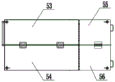
As shown in fig. 6-8, the operation platform 5 is detachably connected to the telescopic arm 4 through a pin or a bolt, two sides of the operation platform 5 are further provided with guardrails 51 detachably connected through a pin or a bolt, and one side of the operation platform 5 is provided with a ladder 52 for an operator to go up and down. The operation platform 5 is specifically a folding type platform and comprises a first platform 53, a second platform 54, a first turning plate 55 and a second turning plate 56, the head end of the first platform 53 is connected with the first turning plate 55 through a hinge, the head end of the second platform 54 is connected with the second turning plate 56 through a hinge, the first platform 53 is connected with the second platform 54 through a hinge, the first turning plate 55 is connected with the second turning plate 56 through a hinge, the hinge and the hinge are arranged, and the first platform 53, the second platform 54, the first turning plate 55 and the second turning plate 56 are foldable.
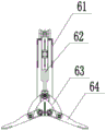
As shown in fig. 9-10, the leg 6 includes a leg main body 61, a leg support foot expansion cylinder 62, a foot grab connecting rod 63 and a leg foot grab 64, the top end of the leg main body 61 is hinged to the telescopic arm 4, one side of the leg main body 61 is connected to the head end of the platform main body overhanging arm frame 3 through a leg overturning cylinder 65, and two ends of the leg overturning cylinder 65 are respectively hinged to the leg main body 61 and the platform main body overhanging arm frame 3; the retraction and the expansion of the supporting legs 6 are completed through the stretching of the supporting leg overturning oil cylinder 65;
the two sides of the bottom end of the supporting leg main body 61 are respectively hinged with a supporting leg claw 64, the supporting leg retracting and expanding oil cylinder 62 is embedded in the supporting leg main body 61, the bottom end of a piston rod of the supporting leg retracting and expanding oil cylinder 62 is hinged with two supporting leg claw connecting rods 63, and the bottom ends of the two supporting leg claw connecting rods 63 are respectively hinged with one supporting leg claw 64; the leg support foot retracting and expanding oil cylinder 62 stretches and retracts to push the foot claw connecting rod to drive the foot claws of the leg support 6 to retract and expand the leg support 6.
As shown in fig. 3, a connecting seat 10 is connected to the mounting seat 8, one end of the connecting seat 10 is connected to the mounting seat 8, and the other end of the connecting seat 10 is connected to one end of a spiral swing cylinder 11;
the connecting seat 10 is connected with the telescopic boom 4 through a drill boom overturning oil cylinder 12, one end of the drill boom overturning oil cylinder 12 is hinged to the top of the telescopic boom 4, and the other end of the drill boom overturning oil cylinder 12 is hinged to the top of the connecting seat 10; the other end of the spiral swing oil cylinder 11 is connected with an anchor rod swing frame 13, two sides of the anchor rod swing frame 13 are respectively provided with a swing angle oil cylinder 14, one end of each of the two swing angle oil cylinders 14 is hinged with the anchor rod swing frame 13, the other end of each of the two swing angle oil cylinders is hinged with two sides of an anchor rod swing seat 15, one side of the anchor rod swing seat 15 is connected with a compensation oil cylinder 16, and a jumbolter propelling assembly 17 or a rock drill propelling assembly (not shown in the figure) is arranged on the; the rock drilling machine or the rock drilling machine can be vertically lifted through the drill boom overturning oil cylinder 12, and the rock drilling machine can be overturned through the left and right rotation of the spiral swing oil cylinder 11 and the left and right rotation of the rock bolt swinging frame 13. The rock bolt swinging seat 15 is rotated by the telescopic cylinders of the two swing angle oil cylinders 14 to complete the deflection motion of the rock bolt drilling machine or the rock drilling machine. The reciprocating compensation movement of the jumbolter propulsion assembly 17 or the rock drill propulsion assembly is completed by the compensation oil cylinder 16. The jumbolter 9 finishes the rotary cutting rock drilling propelling action of the power head of the anchor rod through a propelling oil cylinder of the propelling assembly.
The utility model discloses the principle and the implementation mode of the utility model are explained by applying the concrete examples, and the explanation of the above examples is only used for helping to understand the method and the core idea of the utility model; meanwhile, for the general technical personnel in the field, according to the idea of the present invention, there are changes in the concrete implementation and the application scope. In summary, the content of the present description should not be construed as a limitation of the present invention.
Claims (8)
1. The utility model provides a take elevating system's brill anchor platform which characterized in that: comprises a working platform main body, a lifting connecting seat, a platform main body cantilever crane, a telescopic arm, an operating platform and a supporting leg, the lifting connecting seat is arranged at the head end of the working platform main body and is connected with a suspension rail main platform in a roadway through a lifting mechanism, the telescopic arm is arranged at the head end of the working platform main body and is connected with the working platform main body through a telescopic oil cylinder, the telescopic oil cylinder controls the telescopic arm to stretch, the cantilever crane of the platform main body is arranged at the head end of the working platform main body, the telescopic arm is connected with the cantilever crane of the platform main body through a guide mechanism, the operating platform is arranged at the top of the head end of the telescopic arm, the support legs are arranged at the bottom of the head end of the telescopic arm, the head end of the telescopic arm is provided with a mounting seat, and the mounting seat is used for mounting a jumbolter or a rock drill;
the lifting mechanism comprises a main platform connecting seat, a deflection seat, an upper arm, a lower arm, a lifting oil cylinder, a drilling anchor platform steering oil cylinder and a lifting mechanism deflection oil cylinder, the main platform connecting base is hinged with the suspension rail main platform through a pin shaft and is also connected with the suspension rail main platform through a lifting mechanism deflection oil cylinder, the eccentric seat is hinged with the main platform connecting seat through a pin shaft, two sides of the eccentric seat are respectively connected with the lifting connecting seat through a lifting mechanism deflection oil cylinder which is transversely arranged, the main platform connecting seat is connected with the top end of the eccentric seat through the upper arm, the two ends of the upper arm are respectively hinged with the main platform connecting seat and the eccentric seat, the bottom ends of the main platform connecting seat and the eccentric seat are connected through the lower arm, and the two ends of the lower arm are respectively hinged with the main platform connecting seat and the eccentric seat; the two sides of the bottom of the main platform connecting seat are respectively hinged with one end of a lifting oil cylinder, and the other ends of the two lifting oil cylinders are respectively hinged with the two sides of the upper arm.
2. The drill-anchor platform with lifting mechanism of claim 1, wherein: the cylinder body end of the telescopic oil cylinder is hinged to the working platform main body, and the piston rod end of the telescopic oil cylinder is hinged to the telescopic arm.
3. The drill-anchor platform with lifting mechanism of claim 1, wherein: the guide mechanism comprises a guide rail and a guide rail seat, the guide rail is arranged on the telescopic arm, the guide rail seat is arranged on the cantilever crane of the platform main body, and the guide rail is connected in the guide rail seat in a sliding manner.
4. The drill-anchor platform with lifting mechanism of claim 1, wherein: the telescopic arm is at least provided with one group.
5. The drill-anchor platform with lifting mechanism of claim 1, wherein: operation platform with the flexible arm is detachable connects, operation platform's both sides still are provided with the guardrail of dismantling the connection, one side of operation platform is provided with the cat ladder that supplies operating personnel to go up and down.
6. The drill-anchor platform with lifting mechanism of claim 1, wherein: the operation platform is a folding type platform and comprises a first platform, a second platform, a first turning plate and a second turning plate, the first end of the first platform is connected with the first turning plate through a hinge, the second end of the second platform is connected with the second turning plate through a hinge, the first platform is connected with the second platform through a hinge, and the first turning plate is connected with the second turning plate through a hinge.
7. The drill-anchor platform with lifting mechanism of claim 1, wherein: the supporting leg comprises a supporting leg main body, a supporting leg extending oil cylinder, a foot grab connecting rod and a supporting leg foot grab, wherein the top end of the supporting leg main body is hinged with the telescopic arm, one side of the supporting leg main body is connected with the head end of an cantilever crane of the platform main body through a supporting leg overturning oil cylinder, and two ends of the supporting leg overturning oil cylinder are respectively hinged with the supporting leg main body and the cantilever crane of the platform main body;
the bottom both sides of landing leg main part articulate respectively and are connected with a landing leg foot and grab, landing leg supporting foot receipts and opens the hydro-cylinder inlay in the landing leg main part, the bottom of the piston rod of landing leg supporting foot receipts and opens the hydro-cylinder is articulated to be connected with two the connecting rod is grabbed to the foot, two the bottom of connecting rod is grabbed to the foot articulates respectively and is connected one the landing leg foot is grabbed.
8. The drill-anchor platform with lifting mechanism of claim 1, wherein: the mounting seat is connected with a connecting seat, one end of the connecting seat is connected with the mounting seat, and the other end of the connecting seat is connected with one end of the spiral swinging oil cylinder;
the connecting seat is connected with the cantilever crane of the platform main body through a drill boom overturning oil cylinder, one end of the drill boom overturning oil cylinder is hinged to the top of the cantilever crane of the platform main body, and the other end of the drill boom overturning oil cylinder is hinged to the top of the connecting seat; the other end of the spiral swing oil cylinder is connected with the anchor rod swing frame, two swing angle oil cylinders are respectively arranged on two sides of the anchor rod swing frame, one end of each swing angle oil cylinder is hinged to the anchor rod swing frame, the other end of each swing angle oil cylinder is hinged to two sides of the anchor rod swing seat, one side of the anchor rod swing seat is connected with the compensation oil cylinder, and the compensation oil cylinder is provided with an anchor rod drilling machine propulsion assembly or a rock drilling machine propulsion assembly.
Priority Applications (1)
| Application Number | Priority Date | Filing Date | Title |
|---|---|---|---|
| CN202021251815.4U CN212614547U (en) | 2020-06-30 | 2020-06-30 | Take elevating system's brill anchor platform |
Applications Claiming Priority (1)
| Application Number | Priority Date | Filing Date | Title |
|---|---|---|---|
| CN202021251815.4U CN212614547U (en) | 2020-06-30 | 2020-06-30 | Take elevating system's brill anchor platform |
Publications (1)
| Publication Number | Publication Date |
|---|---|
| CN212614547U true CN212614547U (en) | 2021-02-26 |
Family
ID=74756874
Family Applications (1)
| Application Number | Title | Priority Date | Filing Date |
|---|---|---|---|
| CN202021251815.4U Active CN212614547U (en) | 2020-06-30 | 2020-06-30 | Take elevating system's brill anchor platform |
Country Status (1)
| Country | Link |
|---|---|
| CN (1) | CN212614547U (en) |
Cited By (1)
| Publication number | Priority date | Publication date | Assignee | Title |
|---|---|---|---|---|
| CN114086893A (en) * | 2021-11-08 | 2022-02-25 | 中国煤炭科工集团太原研究院有限公司 | Telescopic structure and drilling machine |
-
2020
- 2020-06-30 CN CN202021251815.4U patent/CN212614547U/en active Active
Cited By (1)
| Publication number | Priority date | Publication date | Assignee | Title |
|---|---|---|---|---|
| CN114086893A (en) * | 2021-11-08 | 2022-02-25 | 中国煤炭科工集团太原研究院有限公司 | Telescopic structure and drilling machine |
Similar Documents
| Publication | Publication Date | Title |
|---|---|---|
| CN111608591A (en) | Take elevating system's brill anchor platform | |
| CN111663896A (en) | Single-track-crane four-arm hydraulic support anchor rod and anchor cable drilling machine for coal mine | |
| CN111622683A (en) | Platform capable of being provided with multiple rows of roof bolters | |
| CN110630301A (en) | Suspension rail wing type anchor rod drill carriage | |
| CN211342765U (en) | Multifunctional impact type hydraulic drill carriage suitable for rock roadway working face construction | |
| CN108590518A (en) | Adjustable anchor rod drilling machine for high slope anchoring | |
| CN110905406A (en) | Multifunctional impact type hydraulic drill carriage suitable for rock roadway working face construction | |
| CN212614547U (en) | Take elevating system's brill anchor platform | |
| CN215369687U (en) | Auxiliary supporting mechanism for drilling of multi-row anchor rods | |
| CN109838244B (en) | Foldable large-area operation platform device | |
| CN214532772U (en) | Single-track-crane four-arm hydraulic support anchor rod and anchor cable drilling machine for coal mine | |
| CN110526141A (en) | A kind of crane arm apparatus for turning of type fast erecting tower crane | |
| CN214196201U (en) | Platform capable of being provided with multiple rows of roof bolters | |
| CN216517834U (en) | Coal mine underground rapid tunneling advanced drilling device | |
| CN206448809U (en) | Pick, branch, anchor, drill integrated fully-mechanized digging machine | |
| CN211397617U (en) | Suspension rail wing type anchor rod drill carriage | |
| CN211230521U (en) | Suspension rail wing type supporting platform | |
| CN215292501U (en) | Cutting device of heading machine and cantilever type longitudinal shaft heading machine | |
| CN214616556U (en) | Working platform with horizontal telescopic mechanism | |
| CN214611383U (en) | Working platform with lifting mechanism | |
| CN211448686U (en) | Anchor protection device and heading machine | |
| CN209838420U (en) | Foldable large-area operating platform device | |
| CN215890016U (en) | Hydraulic drill carriage suitable for head-on and roof double protection | |
| CN110578543A (en) | Suspension rail wing type supporting platform | |
| CN215672037U (en) | Anchor rod drill carriage |
Legal Events
| Date | Code | Title | Description |
|---|---|---|---|
| GR01 | Patent grant | ||
| GR01 | Patent grant |