CN212496964U - Toughened glass edge grinding machine - Google Patents
Toughened glass edge grinding machine Download PDFInfo
- Publication number
- CN212496964U CN212496964U CN202021312262.9U CN202021312262U CN212496964U CN 212496964 U CN212496964 U CN 212496964U CN 202021312262 U CN202021312262 U CN 202021312262U CN 212496964 U CN212496964 U CN 212496964U
- Authority
- CN
- China
- Prior art keywords
- toughened glass
- fixed
- slide
- roof
- fluted disc
- Prior art date
- Legal status (The legal status is an assumption and is not a legal conclusion. Google has not performed a legal analysis and makes no representation as to the accuracy of the status listed.)
- Active
Links
Images

Landscapes
- Grinding And Polishing Of Tertiary Curved Surfaces And Surfaces With Complex Shapes (AREA)
Abstract
The utility model belongs to the edging machine field discloses a toughened glass edging machine for solve the problem of current circular toughened glass edging unevenness. The grinding roller is installed at the bottom of the first sliding plate, a movable plate is fixed on a side wall, close to the top center of the top plate, of the first sliding plate, a fluted disc is arranged above the movable plate, a guide plate in sliding connection with the movable plate is fixed at the bottom of the fluted disc, and the guide plate is of a spiral structure. The utility model discloses simple structure, three roller of polishing is polished toughened glass in step, has guaranteed the machining precision, operates steadily to make the toughened glass edging more even, the machining precision is high, is applicable to the circular shape toughened glass of different diameters, and application scope is wide.
Description
Technical Field
The utility model relates to an edging machine technical field especially relates to a toughened glass edging machine.
Background
The existing glass edge grinding adopts the mode that universal wheels or balls are installed on a workbench, edge grinding glass is arranged on the workbench, and the mode that the edge grinding glass is manually and rotationally controlled is adopted to grind the glass, so that the positioning effect is poor, the ground edge is not flat, the roundness of the periphery of the glass is poor, the processing period is long, the labor intensity of an operator is high, and the high-precision glass is difficult to process.
SUMMERY OF THE UTILITY MODEL
The utility model aims at solving the problem of uneven edging of round toughened glass in the prior art and providing a toughened glass edging machine.
In order to achieve the above purpose, the utility model adopts the following technical scheme:
the utility model provides a toughened glass edging machine, includes the roof, the top of roof is equipped with the thing passageway of putting of three evenly distributed, and is three put the crossing vertical straight line of the vertical plane of thing passageway place and the coincidence of the vertical straight line of roof central point place, and the top sliding connection of roof has the slide one that is located thing passageway top, and the grinding roller is installed to the bottom of slide one, is fixed with the fly leaf on the lateral wall that is close to roof top center of slide one, and the top of fly leaf is equipped with the fluted disc, and the bottom of fluted disc is fixed with the deflector with fly leaf sliding connection, and the deflector is helical structure.
Preferably, the top of fly leaf is equipped with curved guide way, and deflector sliding connection is in the guide way, and the guide way plays limiting displacement to the deflector, and the deflector is along with the rotatory in-process of fluted disc, three fly leaf synchronous motion.
Preferably, the top of the first sliding plate is fixed with a second sliding plate which is connected with the inside of the object placing channel in a sliding mode, the top of the first sliding plate is provided with a first driving motor, the output end of the first driving motor penetrates through the first sliding plate and the second sliding plate and is used for fixing the grinding roller through a coupler, the arrangement of the coupler enables the grinding roller to be stably connected with the output end of the driving motor, the grinding roller is not prone to fracture, and the service life of the device is prolonged.
Preferably, the bottom of the fluted disc is rotatably connected to the top of the top plate through a rotating rod, and a second driving motor for driving the fluted disc to rotate is fixed to the top of the top plate.
Preferably, the below of roof is equipped with the fixed station, and the top of fixed station is fixed with electric turntable, and electric turntable's top is fixed with circular shape toughened glass through electric chuck, and toughened glass is fixed firmly, and the machining precision is high.
The utility model has the advantages that:
1. the device is simple in structure, the three movable plates synchronously move through the rotating fluted disc and the guide plate, the movable plates drive the first sliding plate, the second sliding plate and the polishing rollers to synchronously approach to the center of the top plate, the electric suction disc is used for fixing toughened glass, the electric rotary disc drives the toughened glass to rotate, and the three polishing rollers synchronously polish the toughened glass, so that the processing precision is ensured, the operation is stable, the edge grinding of the glass edge grinding machine is more uniform, and the processing precision of the glass is improved;
2. the three movable plates are synchronously close to or far away from the center of the top plate, the relative positions of the three grinding rollers are adjusted, and the three movable plates are suitable for round toughened glass with different diameters, and the application range is wide.
Drawings
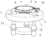
Fig. 1 is a schematic structural view of a toughened glass edge grinding machine provided by the utility model;
fig. 2 is the utility model provides an among the toughened glass edging machine, the relation of connection sketch map of fly leaf and deflector.
In the figure: 1. a top plate; 2. a storage channel; 3. a first sliding plate; 4. grinding a roller; 5. a movable plate; 6. a fluted disc; 7. a guide plate; 8. a guide groove; 9. driving a motor I; 10. a second driving motor; 11. rotating the rod; 12. a coupling; 13. and (4) tempering the glass.
Detailed Description
The technical solutions in the embodiments of the present invention will be described clearly and completely with reference to the accompanying drawings in the embodiments of the present invention, and it is obvious that the described embodiments are only some embodiments of the present invention, not all embodiments.
Referring to fig. 1-2, a toughened glass edge grinding machine comprises a top plate 1, wherein three uniformly distributed object placing channels 2 are arranged at the top of the top plate 1, vertical straight lines intersecting a vertical plane where the three object placing channels 2 are located coincide with a vertical straight line where a central point of the top plate 1 is located, a first sliding plate 3 located above the object placing channels 2 is slidably connected to the top of the top plate 1, a grinding roller 4 is installed at the bottom of the first sliding plate 3, a movable plate 5 is fixed on a side wall, close to the center of the top plate 1, of the first sliding plate 3, a fluted disc 6 is arranged above the movable plate 5, a guide plate 7 slidably connected with the movable plate 5 is fixed at the bottom of the fluted disc 6, the guide plate 7 is of a spiral structure, an arc-shaped guide groove 8 is arranged at the top of the movable plate 5, the guide plate 7 is slidably connected in the guide groove 8, 5 synchronous motion of three fly leaf, slide one 3's top is fixed with sliding connection in putting the slide two in the thing passageway 2, driving motor 9 is installed at slide one 3's top, driving motor 9's output runs through slide one 3 and slide two and through the fixed grinding roller 4 of polishing of shaft coupling 12, the setting up of shaft coupling 12 makes grinding roller 4 and driving motor output connect stably, difficult fracture, device life has been prolonged, the bottom of fluted disc 6 is rotated through dwang 11 and is connected in the top of roof 1, the top of roof 1 is fixed with two 10 of driving fluted disc 6 pivoted driving motor, the below of roof 1 is equipped with the fixed station, the top of fixed station is fixed with electric turntable, electric turntable's top is fixed with circular shape toughened glass 13 through electric chuck, toughened glass 13 is fixed firm, the machining precision is high.
The working principle is as follows: firstly, toughened glass 13 is fixed with the electric turntable at the top of the fixed station through an electric sucker, at the moment, the central point of toughened glass 13, the central point of electric turntable and the central point of top plate 1 are located on the same vertical straight line, two 10 driving motors work to enable fluted disc 6 to rotate, guide plate 7 slides in guide groove 8 and enables movable plate 5 to move towards the center of top plate 1, two driving rollers 4 of slide one 3 and slide move towards toughened glass 13, one 9 driving motors work to enable polishing rollers 4 to rotate, electric turntable rotates, and polishing rollers 4 carry out edging treatment on glass.
The above, only be the concrete implementation of the preferred embodiment of the present invention, but the protection scope of the present invention is not limited thereto, and any person skilled in the art is in the technical scope of the present invention, according to the technical solution of the present invention and the utility model, the concept of which is equivalent to replace or change, should be covered within the protection scope of the present invention.
Claims (5)
1. The utility model provides a toughened glass edging machine, includes roof (1), its characterized in that: the top of roof (1) is equipped with three evenly distributed's thing passageway (2) of putting, it is three put the crossing vertical straight line of the vertical plane of thing passageway (2) place and the coincidence of the vertical straight line of roof (1) central point place, the top sliding connection of roof (1) has slide (3) that are located thing passageway (2) top, the grinding roller (4) are installed to the bottom of slide (3), be fixed with fly leaf (5) on the lateral wall that is close to roof (1) top center of slide (3), the top of fly leaf (5) is equipped with fluted disc (6), the bottom of fluted disc (6) is fixed with deflector (7) with fly leaf (5) sliding connection, deflector (7) are helical structure.
2. A toughened glass edging machine according to claim 1, characterized in that: the top of fly leaf (5) is equipped with curved guide way (8), and deflector (7) sliding connection is in guide way (8).
3. A toughened glass edging machine according to claim 1, characterized in that: the top of slide one (3) is fixed with sliding connection and puts the slide two in thing passageway (2), and driving motor one (9) are installed at the top of slide one (3), and the output of driving motor one (9) runs through slide one (3) and slide two and pass through shaft coupling (12) fixed grinding roller (4).
4. A toughened glass edging machine according to claim 1, characterized in that: the bottom of fluted disc (6) is rotated through dwang (11) and is connected in the top of roof (1), and the top of roof (1) is fixed with drive fluted disc (6) pivoted driving motor two (10).
5. A toughened glass edging machine according to claim 1, characterized in that: the lower part of roof (1) is equipped with the fixed station, and the top of fixed station is fixed with electric turntable, and electric turntable's top is fixed with circular shape toughened glass (13) through electric chuck.
Priority Applications (1)
| Application Number | Priority Date | Filing Date | Title |
|---|---|---|---|
| CN202021312262.9U CN212496964U (en) | 2020-07-07 | 2020-07-07 | Toughened glass edge grinding machine |
Applications Claiming Priority (1)
| Application Number | Priority Date | Filing Date | Title |
|---|---|---|---|
| CN202021312262.9U CN212496964U (en) | 2020-07-07 | 2020-07-07 | Toughened glass edge grinding machine |
Publications (1)
| Publication Number | Publication Date |
|---|---|
| CN212496964U true CN212496964U (en) | 2021-02-09 |
Family
ID=74436171
Family Applications (1)
| Application Number | Title | Priority Date | Filing Date |
|---|---|---|---|
| CN202021312262.9U Active CN212496964U (en) | 2020-07-07 | 2020-07-07 | Toughened glass edge grinding machine |
Country Status (1)
| Country | Link |
|---|---|
| CN (1) | CN212496964U (en) |
-
2020
- 2020-07-07 CN CN202021312262.9U patent/CN212496964U/en active Active
Similar Documents
| Publication | Publication Date | Title |
|---|---|---|
| CN111360645B (en) | Building material grinding device | |
| CN212496964U (en) | Toughened glass edge grinding machine | |
| CN101125412A (en) | Grinding and cutting method for disk like part end face groove | |
| CN215036097U (en) | Deburring device | |
| CN105057790A (en) | Full-automatic diamond saw blade double-faced sharpening machine | |
| CN213917433U (en) | Grinding device is used in production of high frequency straight welded pipe | |
| CN209737276U (en) | polishing machine for producing linear bearing | |
| CN204893091U (en) | Full -automatic edging machine's of diamond saw blade rotatory and two -sided grinding mechanism of saw bit | |
| CN209717245U (en) | A kind of half Round Edging Machine being ground big seamed edge | |
| CN204867644U (en) | Two -sided edging machine of full -automatic diamond saw blade | |
| CN220548041U (en) | Automatic glass edging processingequipment of changing | |
| CN220217956U (en) | Stone material processing burnishing machine | |
| CN219582523U (en) | Automatic turn-over type polishing wire drawing machine | |
| CN214642341U (en) | Table surface treatment device for teaching desk production and processing | |
| CN217728138U (en) | Rectangular rod piece polisher | |
| CN109986134A (en) | A kind of saw blade grinding apparatus | |
| CN210756956U (en) | Small-size grinding device capable of grinding in all directions for machining nonmagnetic ring | |
| CN221159634U (en) | Clamping device of cylindrical grinding machine | |
| CN221495564U (en) | Polishing machine for processing fan-shaped blade grid test piece | |
| CN221871364U (en) | Surface treatment device for building stone column processing | |
| CN213004345U (en) | High-precision verticality grinding device for optical element | |
| CN219521596U (en) | Shaft part polishing device | |
| CN220388998U (en) | Workpiece polishing device | |
| CN221871425U (en) | Linear double-sided edging machine | |
| CN220863579U (en) | Chamfering device for plate machining |
Legal Events
| Date | Code | Title | Description |
|---|---|---|---|
| GR01 | Patent grant | ||
| GR01 | Patent grant |