CN212492717U - Low-speed mixer - Google Patents
Low-speed mixer Download PDFInfo
- Publication number
- CN212492717U CN212492717U CN202020889631.4U CN202020889631U CN212492717U CN 212492717 U CN212492717 U CN 212492717U CN 202020889631 U CN202020889631 U CN 202020889631U CN 212492717 U CN212492717 U CN 212492717U
- Authority
- CN
- China
- Prior art keywords
- stirring
- fixedly connected
- shaft
- bevel gear
- cylinder
- Prior art date
- Legal status (The legal status is an assumption and is not a legal conclusion. Google has not performed a legal analysis and makes no representation as to the accuracy of the status listed.)
- Expired - Fee Related
Links
Images


Abstract
The utility model relates to a macromolecular material preparation field discloses a low-speed mixer, it includes a jar body, jar body lower extreme is equipped with agitator motor, the agitator motor output shaft passes jar body and is connected with the (mixing) shaft, a plurality of stirring vane of (mixing) shaft fixedly connected with, the (mixing) shaft middle part is equipped with the bar shaped plate, the bar shaped plate includes bottom plate and two curb plates, (mixing) shaft middle part fixedly connected with bevel gear one, two curb plates all rotate and are connected with the horizontal pole, horizontal pole fixedly connected with bevel gear two, two bevel gear two all mesh mutually with bevel gear one, the horizontal pole is fixed. Stirring vane stirs the mixture to the material, and the (mixing) shaft drives bevel gear and rotates, and bevel gear drives two horizontal poles and rotates, and then the agitator disk rotates, and the agitator disk smashes the mixture to the material that is close to jar internal wall one end, improves the stirring effect to the material, through setting up horizontal pole and a plurality of agitator disk, has increased the stirring area to the material, and is comparatively comprehensive even to the stirring of material.
Description
Technical Field
The utility model belongs to the technical field of the macromolecular material preparation and specifically relates to a low-speed mixer is related to.
Background
At present, in the field of preparation of high polymer materials, rubber is a common high polymer material, rubber auxiliaries can bring high added value to rubber products, and a large class of rubber auxiliaries for rubber processing comprises auxiliaries such as a scorch retarder, an anti-aging agent, a softener and a plasticizer. In the production and preparation process of the rubber, a rubber auxiliary agent is needed to be used for increasing the resistance of the rubber and products thereof, delaying or inhibiting the aging process, prolonging the storage period and service life of the rubber and products thereof and improving the comprehensive use performance of the rubber. When the rubber auxiliary is added into the preparation production of rubber, the rubber auxiliary needs to be mixed and stirred, so that the rubber auxiliary is uniformly mixed.
Chinese patent publication No. CN204583053U discloses a rubber auxiliary mixer, comprising: the base, the left socle, including a motor, an end cap, a controller, and a cover plate, the speed reducer, the drive shaft, the right branch frame, the driven shaft, the material shell, agitator motor, spiral stirring shaft, the inlet pipe, the inlet tube lid, the discharging pipe, ejection of compact pipe lid, the vertical welding of left socle is at the base left end, the input shaft of speed reducer and the output shaft rigid coupling of motor, the left end of drive shaft passes through the shaft coupling and is connected with the output shaft of speed reducer, the vertical welding of right branch frame is at the right-hand member of base, the driven shaft passes through bearing horizontal installation on the right branch frame, agitator motor is installed respectively through the bolt in.
The above prior art solutions have the following drawbacks: above-mentioned rubber auxiliary material blendor is in the use, and the material shell rotates along with the drive shaft, and inside material is stirred by two spiral stirring shaft, and the material that is close to material shell inner wall is far away from spiral stirring shaft, and this part material stirring is not abundant inadequately, and is comprehensive even inadequately to the stirring of material.
SUMMERY OF THE UTILITY MODEL
The utility model aims at providing a low-speed mixer, it has comparatively comprehensive even advantage to the material stirring to the not enough of prior art existence.
The above utility model discloses an above-mentioned utility model purpose can realize through following technical scheme:
the utility model provides a low-speed mixer, includes a jar body, jar body lower extreme is equipped with the motor cabinet, the motor cabinet is equipped with agitator motor, jar body is equipped with the top cap, is equipped with the feeder hopper on the top cap, agitator motor output shaft passes a jar body coupling and has the (mixing) shaft, a plurality of stirring vane of (mixing) shaft outer wall fixedly connected with, the (mixing) shaft middle part is equipped with hollow bar shaped plate, the bar shaped plate includes bottom plate and two curb plates that are parallel to each other, the (mixing) shaft passes the bar shaped plate and rotates with the bar shaped plate to be connected, (mixing) shaft middle part fixedly connected with bevel gear one, two curb plates all rotate and are connected with the horizontal pole, and the horizontal pole is worn to establish the curb plate and is close to the one end fixedly connected.
Through adopting the above technical scheme, above-mentioned low-speed mixer is in the use, the material is internal from feeder hopper department with the jar, agitator motor drives the (mixing) shaft and rotates, stirring vane stirs the mixture to the material, the (mixing) shaft drives bevel gear and rotates, two bevel gear two all mesh with bevel gear, bevel gear drives two horizontal poles and rotates, and then the agitator disk rotates, the agitator disk smashes the mixture to the material that is close to jar internal wall one end, the stirring effect to the material is improved, through setting up horizontal pole and a plurality of agitator disk, the stirring area to the material has been increased, stirring to the material is comparatively comprehensive even.
The present invention may be further configured in a preferred embodiment as: the stirring shaft is fixedly connected with a plurality of shifting plates along the axial direction, the shifting plates are positioned between adjacent stirring blades, and a gap exists between one end, away from the stirring shaft, of each shifting plate and the inner wall of the tank body.
Through adopting above-mentioned technical scheme, the (mixing) shaft is stirring the in-process, and the switch plate is stirred the material, improves the mobility of the internal material of jar, is favorable to improving the stirring effect to the material.
The present invention may be further configured in a preferred embodiment as: the tank body is characterized in that a tripod is fixedly connected to the upper end part of the inner wall of the tank body, a circular ring is arranged at the center of the tripod, and the circular ring is rotatably connected with the upper end part of the stirring shaft.
Through adopting above-mentioned technical scheme, the (mixing) shaft rotates the in-process, and stirring vane stirs the mixture to the material, and the (mixing) shaft middle part is rotated and is connected with the bar shaped plate for the stress that the (mixing) shaft upper end received is great, sets up the tripod, and the ring rotates with the (mixing) shaft upper end to be connected, improves the stability of (mixing) shaft when rotating.
The present invention may be further configured in a preferred embodiment as: the bearing is arranged at the joint of the side plate and the cross rod, the cross rod is fixed with the inner ring of the bearing, and the side plate is fixed with the outer ring of the bearing.
Through adopting above-mentioned technical scheme, set up the bearing for the horizontal pole is in rotating the in-process, is favorable to improving the stability of horizontal pole and curb plate when rotating, the steady operation of the agitator disk of being convenient for.
The present invention may be further configured in a preferred embodiment as: the lower end of the bevel gear is rotatably connected with the bottom plate, the lower end of the strip-shaped plate is fixedly connected with a plurality of fixing rods, and the fixing rods are fixedly connected with the inner wall of the tank body.
By adopting the technical scheme, the first bevel gear is rotationally connected with the bottom plate, so that the friction force between the first bevel gear and the bottom plate is favorably reduced, the first bevel gear is stable in working, and the service life of the first bevel gear is prolonged; the fixed rod fixes the strip-shaped plate, the strip-shaped plate is always fixed in the stirring process, and the transmission of the bevel gear I and the bevel gear II is stable, so that the improvement on the stirring effect of the material is facilitated.
The present invention may be further configured in a preferred embodiment as: the end lateral wall is equipped with the discharge gate under jar body, jar external wall fixedly connected with cylinder one, a cylinder output shaft fixedly connected with and the apron of discharge gate looks adaptation.
Through adopting above-mentioned technical scheme, when unloading, cylinder one drives the apron and removes to keeping away from discharge gate one end for the apron breaks away from the discharge gate, the discharge of the material of being convenient for.
The present invention may be further configured in a preferred embodiment as: a hollow cylinder is arranged between the first cylinder and the tank body, the cylinder is connected with the cover plate in a sliding mode, and an inclined discharge pipe is arranged at the lower end of the cylinder.
Through adopting above-mentioned technical scheme, the drum can avoid producing when the apron breaks away from the discharge gate and fly upward the loss material, and the discharge tube of slope makes to unload and collect comparatively convenient.
The present invention may be further configured in a preferred embodiment as: the outer wall of the tank body is fixedly connected with a second air cylinder, an output shaft of the second air cylinder is fixedly connected with an annular block, a top cover is fixedly connected with a connecting rod, one end, away from the top cover, of the connecting rod is rotatably connected with the annular block, the upper end portion of the tank body is provided with a locking handle at equal angles along the circumferential direction, and the top cover is provided with a bayonet matched with the locking handle.
Through adopting above-mentioned technical scheme, when needing to open the top cap, earlier with locking handle and bayonet socket separation, the annular block jack-up is opened to two output shafts of cylinder, and then rotates the top cap, and the connecting rod rotates around the annular block and opens the top cap, and it is comparatively convenient to open, and locking handle and bayonet socket cooperation strengthen the leakproofness of jar body when the stirring, avoid the material to fly upward from the top cap when stirring.
To sum up, the utility model discloses a following at least one useful technological effect:
1. the material is added into the tank body from the feeding hopper, the stirring motor drives the stirring shaft to rotate, the stirring blades stir and mix the material, the stirring shaft drives the bevel gear I to rotate, the two bevel gears II are both meshed with the bevel gear I, the bevel gear I drives the two cross rods to rotate, and further the stirring disc rotates, the stirring disc crushes and mixes the material close to one end of the inner wall of the tank body, the stirring effect on the material is improved, the stirring area on the material is increased by arranging the cross rods and the stirring discs, and the material is stirred more comprehensively and uniformly;
2. in the stirring process of the stirring shaft, the material is stirred by the stirring plate, so that the fluidity of the material in the tank body is improved, and the effect of uniformly stirring the material is improved;
3. the (mixing) shaft rotates the in-process, and stirring vane stirs the mixture to the material, and the (mixing) shaft middle part rotates and is connected with the bar shaped plate for the stress that the (mixing) shaft upper end received is great, sets up the tripod, and the ring rotates with the (mixing) shaft upper end to be connected, improves the stability of (mixing) shaft when rotating.
Drawings
FIG. 1 is a schematic view of the overall structure of the embodiment;
FIG. 2 is a schematic view of the interior of the can body;
FIG. 3 is a schematic view of the engagement of a first bevel gear with a second bevel gear;
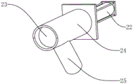
fig. 4 is intended to highlight the connection of the first cylinder to the cover.
In the figure, 1, a tank body; 2. a motor base; 3. a stirring motor; 4. a top cover; 5. a feed hopper; 6. a stirring shaft; 7. a stirring blade; 8. a strip plate; 10. a base plate; 11. a side plate; 12. a first bevel gear; 13. a cross bar; 14. a second bevel gear; 15. a stirring plate; 16. a kick-out plate; 18. a tripod; 19. a circular ring; 20. a bearing; 21. fixing the rod; 22. a first cylinder; 23. a cover plate; 24. a cylinder; 25. a discharge pipe; 26. a second air cylinder; 27. a ring block; 28. a connecting rod; 29. and locking the handle.
Detailed Description
The present invention will be described in further detail with reference to the accompanying drawings.
Referring to fig. 1, for the utility model discloses a low-speed mixer, which comprises a tank body 1, 1 lower extreme of jar body is equipped with motor cabinet 2, motor cabinet 2 is equipped with agitator motor 3, jar body 1 is equipped with top cap 4, be equipped with feeder hopper 5 on the top cap 4, operating personnel need regularly wash the maintenance to jar body 1, jar body 1 outer wall fixedly connected with cylinder two 26, cylinder two 26 output shaft fixedly connected with annular block 27, top cap 4 fixedly connected with connecting rod 28, the one end that top cap 4 was kept away from to connecting rod 28 rotates with annular block 27 to be connected, the angle such as circumference is equipped with locking handle 29 on the 1 upper end of jar body, be equipped with the bayonet socket with locking handle 29 looks adaptation on the top.
Referring to fig. 1, when the top cover 4 needs to be opened, the locking handle 29 is separated from the bayonet, the output shaft of the second air cylinder 26 jacks up the ring block 27, so that the height of the top cover 4 is slightly larger than the original height, and then the top cover 4 is rotated, and the connecting rod 28 rotates around the ring block 27 to open the top cover 4. The locking handle 29 is matched with the bayonet, so that the sealing performance of the tank body 1 during stirring is enhanced, and materials are prevented from flying from the top cover 4 during stirring.
Refer to fig. 2 and 3, 3 output shafts of agitator motor pass jar body 1 (refer to fig. 1) and are connected with (mixing) shaft 6, a plurality of stirring vane 7 of 6 outer wall fixedly connected with of (mixing) shaft, 6 middle parts of (mixing) shaft are equipped with hollow bar shaped plate 8, bar shaped plate 8 includes bottom plate 10 and two curb plates 11 that are parallel to each other, (mixing) shaft 6 passes bar shaped plate 8 and rotates with bar shaped plate 8 and is connected, 6 middle part fixedly connected with bevel gear 12 of (mixing) shaft, two curb plates 11 all rotate and are connected with horizontal pole 13, horizontal pole 13 wears to establish curb plate 11 and is close to the one end fixedly connected with bevel gear two 14 of (mixing) shaft 6, two bevel gear two 14 all mesh with bevel gear 12 mutually, horizontal pole.
Referring to fig. 2 and 3, low-speed mixer is in the use, the material is from feeder hopper 5 (refer to fig. 1) in adding jar body 1 (refer to fig. 1), agitator motor 3 drives (mixing) shaft 6 and rotates, and then stirring vane 7 stirs the mixture to the material in jar body 1 (refer to fig. 1), the (mixing) shaft 6 drives bevel gear 12 in the strip 8 and rotates, bevel gear 14 on two horizontal poles 13 all meshes with bevel gear 12, bevel gear 12 drives two horizontal poles 13 and rotates, and then make agitator disk 15 on the horizontal pole 13 rotate, agitator disk 15 smashes the mixture to the material that is close to jar body 1 (refer to fig. 1) inner wall one end, improve the stirring effect to the material, through setting up horizontal pole 13 and a plurality of agitator disk 15, increased the stirring area to the material, it is comparatively comprehensive even to the stirring of material.
Referring to fig. 2 and 3, agitator motor 3 drives (mixing) shaft 6 and rotates the in-process, and stirring vane 7 stirs the mixture to the material, and (mixing) shaft 6 middle part is rotated and is connected with strip shaped plate 8, is equipped with subassembly such as bevel gear 12 and bevel gear two 14 in the strip shaped plate 8 for the stress that the upper end of (mixing) shaft 6 receives is great, jar body 1 (refer to 1) inner wall upper end fixedly connected with tripod 18, and tripod 18 center is equipped with ring 19, and ring 19 rotates with (mixing) shaft 6 upper end to be connected. Set up tripod 18, ring 19 rotates with (mixing) shaft 6 upper end to be connected, strengthens the steadiness of (mixing) shaft 6 upper end, improves the stability of (mixing) shaft 6 when rotating.
Referring to fig. 2 and 3, the stirring shaft 6 is fixedly connected with a plurality of material shifting plates 16 along the axial direction, the material shifting plates 16 are positioned between adjacent stirring blades 7, and a gap exists between one end of each material shifting plate 16 far away from the stirring shaft 6 and the inner wall of the tank body 1 (refer to fig. 1). Set up switch board 16 for (mixing) shaft 6 is stirring the in-process, and switch board 16 stirs the material, improves the mobility of material, and the material of being convenient for flows to stirring vane 7 and 15 departments of agitator disk, is favorable to improving the even stirring effect to the material. The bearing 20 is arranged at the joint of the lateral plate 11 and the cross rod 13, the inner ring of the cross rod 13 and the bearing 20 is fixed, the outer ring of the lateral plate 11 and the outer ring of the bearing 20 are fixed, and the bearing 20 is arranged, so that the cross rod 13 is favorable for improving the stability of the cross rod 13 and the lateral plate 11 during rotation in the rotation process, and the stirring disc 15 is convenient to stably operate.
Referring to fig. 2 and 3, the lower end of the first bevel gear 12 is rotatably connected with the bottom plate 10, and the first bevel gear 12 is rotatably connected with the bottom plate 10, so that the friction between the first bevel gear 12 and the bottom plate 10 is reduced, the first bevel gear 12 is stable in operation, and the service life of the first bevel gear 12 is prolonged; a plurality of dead levers 21 of tip fixedly connected with under the bar shaped plate 8, dead lever 21 and jar body 1 (refer to fig. 1) inner wall fixed connection, dead lever 21 fixes bar shaped plate 8, and bar shaped plate 8 remains fixed throughout at stirring in-process, and bevel gear 12 and bevel gear two 14 driven are comparatively stable, and then make 15 steady operation of agitator disk, are favorable to improving the stirring effect to the material.
Referring to fig. 1 and 4, the tip lateral wall is equipped with the discharge gate under jar body 1, jar body 1 outer wall fixedly connected with cylinder 22, cylinder 22 output shaft fixedly connected with the apron 23 of discharge gate looks adaptation, when unloading, cylinder 22 drives apron 23 and removes to keeping away from discharge gate one end for apron 23 breaks away from the discharge gate, the discharge of the material of being convenient for.
Referring to fig. 1 and 4, most of the materials are granular or powdery after being stirred and mixed, the materials are easy to fly when being discharged from a discharge port, a hollow cylinder 24 is arranged between the first cylinder 22 and the tank body 1, the cylinder 24 is in sliding connection with a cover plate 23, and the lower end part of the cylinder 24 is provided with an inclined discharge pipe 25. The cylinder 24 prevents the cover plate 23 from flying when being separated from the discharge port, and the inclined discharge pipe 25 facilitates discharging and collecting.
The implementation principle of the embodiment is as follows: when the low-speed mixer is used, materials are added into the tank body 1 from the feed hopper 5 on the top cover 4, the stirring motor 3 drives the stirring shaft 6 to rotate, the ring 19 is rotationally connected with the upper end part of the stirring shaft 6, the material is stirred by the stirring plate 16 in the stirring process, the fluidity of the materials in the tank body 1 is improved, the materials can conveniently flow to the stirring blades 7 and the stirring discs 15, the materials in the tank body 1 are stirred and mixed by the stirring blades 7, the stirring shaft 6 drives the bevel gears 12 in the strip-shaped plates 8 to rotate, the bevel gears 14 on the two transverse rods 13 are both meshed with the bevel gears 12, the bevel gears 12 drive the two transverse rods 13 to rotate, the stirring discs 15 on the transverse rods 13 are further rotated, the stirring discs 15 crush and mix the materials close to one end of the inner wall of the tank body 1, the stirring effect on the materials is improved, and the stirring area on the materials is increased by arranging the transverse, the stirring to the material is comparatively comprehensive even.
The embodiment of this specific implementation mode is the preferred embodiment of the present invention, not limit according to this the utility model discloses a protection scope, so: all equivalent changes made according to the structure, shape and principle of the utility model are covered within the protection scope of the utility model.
Claims (8)
1. The utility model provides a low-speed mixer, includes jar body (1), its characterized in that: the stirring tank is characterized in that a motor base (2) is arranged at the lower end of the tank body (1), a stirring motor (3) is arranged on the motor base (2), a top cover (4) is arranged on the tank body (1), a feeding hopper (5) is arranged on the top cover (4), an output shaft of the stirring motor (3) penetrates through the tank body (1) to be connected with a stirring shaft (6), a plurality of stirring blades (7) are fixedly connected to the outer wall of the stirring shaft (6), a hollow strip-shaped plate (8) is arranged in the middle of the stirring shaft (6), the strip-shaped plate (8) comprises a bottom plate (10) and two side plates (11) which are parallel to each other, the stirring shaft (6) penetrates through the strip-shaped plate (8) and is rotatably connected with the strip-shaped plate (8), a bevel gear I (12) is fixedly connected to the middle of the stirring shaft (6), both the two side plates (11) are rotatably, the two bevel gears II (14) are meshed with the bevel gears I (12), and a plurality of stirring discs (15) are fixed on the parts, located outside the strip-shaped plates (8), of the cross rods (13) at equal intervals.
2. A low speed mixer as claimed in claim 1, wherein: the stirring shaft (6) is fixedly connected with a plurality of material shifting plates (16) along the axial direction, the material shifting plates (16) are positioned between the adjacent stirring blades (7), and a gap exists between one end, away from the stirring shaft (6), of each material shifting plate (16) and the inner wall of the tank body (1).
3. A low speed mixer as claimed in claim 1, wherein: the tank body (1) is characterized in that a tripod (18) is fixedly connected to the upper end of the inner wall of the tank body, a circular ring (19) is arranged at the center of the tripod (18), and the circular ring (19) is rotatably connected with the upper end of the stirring shaft (6).
4. A low speed mixer as claimed in claim 1, wherein: the bearing (20) is arranged at the joint of the side plate (11) and the cross rod (13), the cross rod (13) is fixed with the inner ring of the bearing (20), and the side plate (11) is fixed with the outer ring of the bearing (20).
5. A low speed mixer as claimed in claim 1, wherein: the lower end of the first bevel gear (12) is rotatably connected with the bottom plate (10), the lower end of the strip-shaped plate (8) is fixedly connected with a plurality of fixing rods (21), and the fixing rods (21) are fixedly connected with the inner wall of the tank body (1).
6. A low speed mixer as claimed in claim 1, wherein: the tip lateral wall is equipped with the discharge gate under jar body (1), jar body (1) outer wall fixedly connected with cylinder (22), apron (23) of cylinder (22) output shaft fixedly connected with and discharge gate looks adaptation.
7. A low speed mixer as claimed in claim 6, wherein: a hollow cylinder (24) is arranged between the cylinder I (22) and the tank body (1), the cylinder (24) is connected with the cover plate (23) in a sliding mode, and an inclined discharge pipe (25) is arranged at the lower end of the cylinder (24).
8. A low speed mixer as claimed in claim 1, wherein: jar body (1) outer wall fixedly connected with cylinder two (26), cylinder two (26) output shaft fixedly connected with annular piece (27), top cap (4) fixedly connected with connecting rod (28), the one end that top cap (4) were kept away from in connecting rod (28) is rotated with annular piece (27) and is connected, and jar body (1) upper end is equipped with locking handle (29) along circumference equiangular, is equipped with the bayonet socket with locking handle (29) looks adaptation on top cap (4).
Priority Applications (1)
| Application Number | Priority Date | Filing Date | Title |
|---|---|---|---|
| CN202020889631.4U CN212492717U (en) | 2020-05-25 | 2020-05-25 | Low-speed mixer |
Applications Claiming Priority (1)
| Application Number | Priority Date | Filing Date | Title |
|---|---|---|---|
| CN202020889631.4U CN212492717U (en) | 2020-05-25 | 2020-05-25 | Low-speed mixer |
Publications (1)
| Publication Number | Publication Date |
|---|---|
| CN212492717U true CN212492717U (en) | 2021-02-09 |
Family
ID=74392862
Family Applications (1)
| Application Number | Title | Priority Date | Filing Date |
|---|---|---|---|
| CN202020889631.4U Expired - Fee Related CN212492717U (en) | 2020-05-25 | 2020-05-25 | Low-speed mixer |
Country Status (1)
| Country | Link |
|---|---|
| CN (1) | CN212492717U (en) |
Cited By (1)
| Publication number | Priority date | Publication date | Assignee | Title |
|---|---|---|---|---|
| CN114486986A (en) * | 2021-12-16 | 2022-05-13 | 四川大学 | Frozen soil freeze thawing test's device |
-
2020
- 2020-05-25 CN CN202020889631.4U patent/CN212492717U/en not_active Expired - Fee Related
Cited By (1)
| Publication number | Priority date | Publication date | Assignee | Title |
|---|---|---|---|---|
| CN114486986A (en) * | 2021-12-16 | 2022-05-13 | 四川大学 | Frozen soil freeze thawing test's device |
Similar Documents
| Publication | Publication Date | Title |
|---|---|---|
| CN206355904U (en) | A kind of dispersing apparatus of the automotive paints with impurity removal function | |
| CN204811957U (en) | Full -automatic high -efficient feed mixer | |
| CN206778559U (en) | A kind of feed grinder with agitating function | |
| CN212492717U (en) | Low-speed mixer | |
| CN203960077U (en) | A kind of equipment of preparing composite fertilizer | |
| CN210138603U (en) | Powder fertilizer mixes machine with screening function | |
| CN219129094U (en) | Mixing arrangement is smashed to boron carbide raw materials | |
| CN106622534A (en) | Mixing and crushing device for fine processing of wheatmeal | |
| CN111070461A (en) | Dual-drive dual-speed-regulation internal mixer | |
| CN115430511B (en) | Environment-friendly stemming mixture grinding method for blast furnace and grinding equipment thereof | |
| CN111151355A (en) | Food crusher for classified crushing and screening | |
| CN212492716U (en) | High-speed stirring device | |
| CN110575897A (en) | Self-suction type feed crushing and stirring machine | |
| CN216884625U (en) | Recycled concrete strengthening production line | |
| CN215353234U (en) | High-efficient emery wheel raw materials compounding equipment | |
| CN112109205B (en) | Mixing device for house building construction | |
| CN212492537U (en) | Vertical blendor of sodium xanthate | |
| CN211803668U (en) | Sand mixing device for hardware production and casting machine | |
| CN210256728U (en) | Mixing arrangement is used in production of concrete admixture | |
| CN210964816U (en) | Slurry mixing device capable of discharging quantitatively for artistic ceramic production | |
| CN210100413U (en) | Quick compounding device of raw materials for cable plastic grain production | |
| CN215549710U (en) | Regenerated cement stirring equipment | |
| CN213854285U (en) | A batching mixes machine for preparing marking coating | |
| CN206229237U (en) | A kind of tilting automobile brake sheet friction material mixer | |
| CN217725337U (en) | W-shaped double-cone efficient mixer |
Legal Events
| Date | Code | Title | Description |
|---|---|---|---|
| GR01 | Patent grant | ||
| GR01 | Patent grant | ||
| CF01 | Termination of patent right due to non-payment of annual fee |
Granted publication date: 20210209 |
|
| CF01 | Termination of patent right due to non-payment of annual fee |