CN212447846U - Four-way walking carrier - Google Patents
Four-way walking carrier Download PDFInfo
- Publication number
- CN212447846U CN212447846U CN201921946815.3U CN201921946815U CN212447846U CN 212447846 U CN212447846 U CN 212447846U CN 201921946815 U CN201921946815 U CN 201921946815U CN 212447846 U CN212447846 U CN 212447846U
- Authority
- CN
- China
- Prior art keywords
- side plates
- walking
- reversing
- ball screw
- vehicle body
- Prior art date
- Legal status (The legal status is an assumption and is not a legal conclusion. Google has not performed a legal analysis and makes no representation as to the accuracy of the status listed.)
- Active
Links
Images


Landscapes
- Handcart (AREA)
Abstract
The utility model provides a four-way walking carrier, which comprises a carrier body, a walking guide device, a reversing device, a jacking device, a driving walking device and a power supply system; wherein walking guider, switching-over device, jacking device, drive running gear, power supply system all set up on the automobile body, the automobile body includes automobile body I and automobile body II, and automobile body I and II both sides of automobile body are equallyd divide and do not are equipped with the walking wheel, power supply system pass through the cable and be connected with switching-over device, jacking device, drive running gear respectively and provide electric power. The utility model provides a quadriversal walking carrier requires quadriversal walking carrier to move to depositing, get the road junction and transport the goods to unloading, deposit road junction and unload or stock in the automatic lane change in many roadways promptly. The utility model discloses an effective effect is that the walking of lane change is access goods nimble, increased storage space utilization, improved the operating efficiency of access goods, saved investment cost.
Description
Technical Field
The utility model relates to a quadriversal walking carrier belongs to logistics storage field.
Background
In recent years, along with the rapid development of modern warehousing industry, higher and higher requirements are provided for the utilization rate of a three-dimensional overhead warehouse, so that more shelves are arranged in the plane layout of the warehouse, more shelf interlayers are arranged in the height direction, the inlet and outlet channels are reduced as much as possible, the utilization rate of the warehousing area is improved, the storage and taking efficiency of goods is accelerated, and the logistics cost is reduced.
At present, the shuttle vehicles mainly have two modes of a straight-running type shuttle vehicle and a primary-secondary type shuttle vehicle, for the straight-running type shuttle vehicle, the direction of conveying goods is limited due to the fact that the straight-running type shuttle vehicle runs on the same track, the straight-running type shuttle vehicle can only reciprocate on a section of linear track, and conveying capacity is low. In the combined mode, because the two vehicles form the combined mode, the vehicles occupy larger space, the number of rows of storage shelves and the interlayer in the height direction are reduced, and the utilization rate of warehouse space is reduced.
Disclosure of Invention
To the problem that straight-line formula shuttle and primary and secondary formula shuttle exist among the high density storage system of current storage industry, in order to satisfy current storage logistics system to the requirement of cargo handling car, in order to improve warehouse space utilization, the utility model aims at providing a quadriversal walking carrier, thereby two side walking wheel drives realize going all around, rely on self to trade in a flexible way in three-dimensional high-rise goods shelves warehouse and realize carrying tray goods.
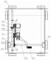
The utility model adopts the technical scheme as follows: a four-way walking carrier comprises a carrier body 1, a walking guide device 2, a reversing device 3, a jacking device 4, a driving walking device 5 and a power supply system 6; the walking guide device 2, the reversing device 3, the jacking device 4, the driving walking device 5 and the power supply system 6 are all arranged on the vehicle body 1, the power supply system 6 is respectively connected with the reversing device 3, the jacking device 4 and the driving walking device 5 through cables, and the walking guide device 2 is arranged on the periphery of the vehicle body 1;
the trolley body 1 comprises a trolley body I1-1 and a trolley body II 1-2, the trolley body I1-1 comprises side plates I1-11, side plates II 1-12 and a bottom plate 1-13, and the side plates I1-11 and the side plates II 1-12 are arranged in parallel and are respectively provided with two travelling wheels 7; the vehicle body II 1-2 comprises side plates III 1-21, side plates IV 1-22 and U-shaped parts 1-23, the two U-shaped parts 1-23 are respectively arranged at the upper ends of the side plates III 1-21 and IV 1-22 in a rotating mode, the side plates III 1-21 and the side plates IV 1-22 are arranged in parallel and are respectively provided with two traveling wheels 7, the traveling wheels 7 on the side plates I1-11 and the side plates II 1-12 are connected through rotating shafts 5-4, and the traveling wheels 7 on the side plates III 1-21 and the side plates IV 1-22 are connected through rotating shafts 5-4; the side plates I1-11, the side plates II 1-12, the side plates III 1-21 and the side plates IV 1-22 form four side plates of the vehicle body 1; jacking devices 4 are respectively arranged on the side plates III 1-21 and the side plates IV 1-22 in a rotating mode, reversing devices 3 are arranged on the bottom plates 1-13 in a rotating mode, the reversing devices 3 are simultaneously connected with U-shaped parts 1-23, driving walking devices 5 are arranged on the bottom plates 1-13, and the driving walking devices 5 can simultaneously drive rotating shafts 5-4 between the side plates I1-11 and walking wheels 7 on the side plates II 1-12 and rotating shafts 5-4 between the side plates III 1-21 and the walking wheels 7 on the side plates IV 1-22.
Specifically, the walking guide device 2 comprises a guide wheel set I2-1, a guide wheel set II 2-2, a guide wheel set III 2-3 and a guide wheel set IV 2-4, wherein the guide wheel set I2-1 is arranged on the lower portion of the outer side of the side plate I1-11, the guide wheel set II 2-2 is arranged on the lower portion of the outer side of the side plate II 1-12, the guide wheel set III 2-3 is arranged on the lower portion of the outer side of the side plate III 1-21, and the guide wheel set IV 2-4 is arranged on the lower portion of the outer side of the side plate IV 1-22.
Specifically, the reversing device 3 comprises a reversing motor 3-1 and four reversing ball screw elevators, the four reversing ball screw elevators are S13-2, S23-3, S33-4 and S43-5 respectively, the reversing motor 3-1, the reversing ball screw elevator S13-2 and the reversing ball screw elevator S23-3 are positioned at one side of the bottom plate 1-13, the reversing ball screw elevator S33-4 and the reversing ball screw elevator S43-5 are positioned at the other side of the bottom plate 1-13 and are connected through a connecting shaft 3-7 and a second coupling 3-6, the reversing motor 3-1 is a double-output-shaft motor, an output shaft at one end of the reversing motor 3-1 is connected with the reversing ball screw elevator S23-3, and an output shaft at the other end is connected with the reversing ball screw elevator S23-3 through the first coupling 3-6 And then, a first chain wheel 3-8 is arranged on a connecting rod of the first coupler 3-6 and the reversing ball screw lifter S23-3, a second chain wheel 3-8 is arranged on a connecting rod between the second coupler 3-6 and the reversing ball screw lifter S33-4, the first chain wheel 3-8 is connected with the second chain wheel 3-8 through a first chain 39, and the end parts of the lifting screw rods of the four ball screw lifters S13-2, S23-3, S33-4 and S43-5 are fixed on U-shaped parts 1-23 of the vehicle body II 1-2 through flanges.
Specifically, the jacking device 4 comprises two groups of jacking mechanisms 4-1, the two groups of jacking mechanisms 4-1 are respectively arranged on a side plate III 1-21 and a side plate IV 1-22, each group of jacking mechanisms 4-1 comprises a jacking motor 4-2 and two ball screw lifters 4-3, the jacking motor 4-2 is a motor with double output shafts, one end of one jacking motor 4-2 is connected with one ball screw lifter 4-3 through an output shaft, and the other end of the one jacking motor 4-2 is connected with the other ball screw lifter 4-3 through a coupler 3-6 for transmission connection.
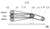
Specifically, the driving walking device 5 comprises a servo motor 5-1, a servo driver 5-2, a driving bevel gear 5-31, a driven bevel gear 5-32, a converter 5-5 and a chain wheel seat 5-6; a servo motor 5-1, a servo driver 5-2 and a chain wheel seat 5-6 are fixed on a bottom plate 1-13 of a vehicle body I1-1, two converters 5-5 are arranged on a side plate III 1-21 and a side plate IV 1-22, and a rotating shaft 5-4 in the vehicle body II 1-2 is in transitional transmission connection with a traveling wheel 7; the driving bevel gears 5-31 and the driving chain wheels 3-81 are connected with an output shaft of the servo motor 5-1, the driving bevel gears 5-31 and driven bevel gears 5-32 arranged on a rotating shaft 5-4 of the vehicle body I1-1 form a pair of transmission sets for power transmission, and the transmission sets drive a travelling wheel 7 in the direction of the vehicle body I1-1 to travel; the driving chain wheels 3-81 are in transmission connection with one row of the double-row chain wheels 3-82 through second chains 3-10, and the other row of the double-row chain wheels 3-82 is connected with driven chain wheels 3-83 arranged on a rotating shaft 5-4 of the vehicle body II 1-2 through third chains 3-11 to drive the travelling wheels 7 in the direction of the vehicle body II 1-2 to travel.
Specifically, the power supply system 6 comprises a direct current power supply 6-1 and a DC-DC module, wherein the direct current power supply 6-1 is electrically connected with the servo motor 5-1, the reversing motor 3-1 and the jacking motor 4-2 through the DC-DC module and supplies power.
The utility model has the advantages that: the utility model discloses a quadriversal walking carrier can move to depositing, get the road junction and transport the goods to unloading, deposit road junction and unload or stock in many roadways automatic lane changing, and lane changing walking access goods is nimble, increased storage space utilization, has improved the operating efficiency of access goods, has saved investment cost.
Drawings
Further objects, functions and advantages of the present invention will become apparent from the following description of embodiments of the present invention, with reference to the accompanying drawings, in which:
FIG. 1 is a schematic elevation view of a main structure of a four-way traveling truck of the present invention with U-shaped members 1-23 removed;
FIG. 2 is a schematic structural plan view of a four-way traveling truck body and a traveling guide device of the present invention;
FIG. 3 is a schematic structural plan view of a reversing device of a four-way traveling truck of the present invention;
FIG. 4 is a schematic structural plan view of a jacking device of a four-way traveling truck of the present invention;
FIG. 5 is a schematic structural plan view of a four-way traveling truck traveling drive device of the present invention;
fig. 6 is a schematic sectional view taken along line a-a in fig. 5.
Fig. 7 is a schematic plan view illustrating the guiding wheel set and the rail guiding system of the guiding device of the four-way traveling carrier of the present invention.
Detailed Description
The objects and functions of the present invention and methods for achieving the objects and functions will be elucidated by reference to exemplary embodiments, however, the present invention is not limited to the exemplary embodiments disclosed below; it can be implemented in different forms. The nature of the description is merely to assist those skilled in the relevant art in a comprehensive understanding of the specific details of the invention.
Embodiments of the present invention will be described below with reference to the accompanying drawings. In the drawings, like reference characters designate the same or similar parts throughout the several views.
Example 1: as shown in fig. 1-6, a four-way traveling truck comprises a truck body 1, a traveling guide device 2, a reversing device 3, a jacking device 4, a driving traveling device 5 and a power supply system 6; the walking guide device 2, the reversing device 3, the jacking device 4, the driving walking device 5 and the power supply system 6 are all arranged on the vehicle body 1, the power supply system 6 is respectively connected with the reversing device 3, the jacking device 4 and the driving walking device 5 through cables, and the walking guide device 2 is arranged on the periphery of the vehicle body 1;
the vehicle body 1 comprises a vehicle body I1-1 and a vehicle body II 1-2, the vehicle body I1-1 comprises a side plate I1-11, a side plate II 1-12 and a bottom plate 1-13, the side plate I1-11 and the side plate II 1-12 are arranged in parallel and are respectively provided with two traveling wheels 7, and when the traveling wheels 7 travel on a track guide system (not shown in the figure, the same below), a four-way traveling carrier enters a goods position track to take goods and stock; the vehicle body II 1-2 comprises side plates III 1-21, side plates IV 1-22 and U-shaped parts 1-23, the two ends of the upper parts of the side plates III 1-21 and the side plates IV 1-22 are respectively connected together through the two U-shaped parts 1-23, namely the side plates III 1-21 and the side plates IV 1-22 are connected into a firm frame through the two U-shaped parts 1-23, the side plates III 1-21 and the side plates IV 1-22 are arranged in parallel and are respectively provided with two walking wheels 7, and when the walking wheels 7 run in a track guide system, the product of the utility model enters a horizontal track guide system to reach any goods position of a goods shelf; the walking wheels 7 on the side plates I1-11 and the side plates II 1-12 are connected through rotating shafts 5-4, and the walking wheels 7 on the side plates III 1-21 and the side plates IV 1-22 are connected through rotating shafts 5-4; the side plates I1-11, the side plates II 1-12, the side plates III 1-21 and the side plates IV 1-22 form four side plates of the vehicle body 1; jacking devices 4 are respectively arranged on the side plates III 1-21 and the side plates IV 1-22 in a rotating mode, reversing devices 3 are arranged on the bottom plates 1-13 in a rotating mode, the reversing devices 3 are simultaneously connected with U-shaped parts 1-23, driving walking devices 5 are arranged on the bottom plates 1-13, and the driving walking devices 5 can simultaneously drive rotating shafts 5-4 between the side plates I1-11 and walking wheels 7 on the side plates II 1-12 and rotating shafts 5-4 between the side plates III 1-21 and the walking wheels 7 on the side plates IV 1-22.
Furthermore, the walking guide device 2 comprises a guide wheel set I2-1, a guide wheel set II 2-2, a guide wheel set III 2-3 and a guide wheel set IV 2-4, wherein the guide wheel set I2-1 is arranged on the lower portion of the outer side of the side plate I1-11, the guide wheel set II 2-2 is arranged on the lower portion of the outer side of the side plate II 1-12, the guide wheel set III 2-3 is arranged on the lower portion of the outer side of the side plate III 1-21, and the guide wheel set IV 2-4 is arranged on the lower portion of the outer side of the side plate IV 1-22. When the product of the utility model travels in the X direction, the guide wheel set I2-1 and the guide wheel set II 2-2 in the travel guide device 2 are matched with the track guide system to guide the travel; when the utility model discloses the product is when Y is to the walking, by direction wheelset III 2-3 and direction wheelset IV 2-4 in the walking guider 2 and the walking of track guidance system cooperation direction, no matter in X to or Y to the walking, all walk through the direction wheelset and the track guidance system direction in the walking guider 2 to reach the effect of revising the direction often, ensure the accuracy and the stability of walking route.
Further, the reversing device 3 comprises a reversing motor 3-1 and four reversing ball screw elevators, the four reversing ball screw elevators are S13-2, S23-3, S33-4 and S43-5 respectively, the reversing motor 3-1, the reversing ball screw elevator S13-2 and the reversing ball screw elevator S23-3 are positioned on one sides of the bottom plates 1-13, the reversing ball screw elevator S33-4 and the reversing ball screw elevator S43-5 are positioned on the other sides of the bottom plates 1-13 and are connected through connecting shafts 3-7 and second couplers 3-6, the reversing motor 3-1 is a double-output-shaft motor, an output shaft at one end of the reversing motor 3-1 is connected with the reversing ball screw elevator S23-3, and an output shaft at the other end is connected with the reversing ball screw elevator S23-3 through the first coupler 3-6 The first chain wheel 3-8 is arranged on a connecting rod of the first coupler 3-6 and the reversing ball screw lifter S23-3, the second chain wheel 3-8 is arranged on a connecting rod between the second coupler 3-6 and the reversing ball screw lifter S33-4, the first chain wheel 3-8 is connected with the second chain wheel 3-8 through the first chain 39, and the end parts of the lifting screw rods of the four ball screw lifters S13-2, S23-3, S33-4 and S43-5 are fixed on U-shaped parts 1-23 of the vehicle body II 1-2 through flanges.
When a right-handed rotating force of a reversing motor 3-1 is transmitted, a reversing ball screw elevator S13-2 and a reversing ball screw elevator S23-3 lead screws are uniformly and upwards lifted, and meanwhile, the reversing ball screw elevator S33-4 and the reversing ball screw elevator S43-5 are synchronously and upwards lifted under the power transmission of a second chain wheel 3-8, a first chain wheel 3-8 and a first chain 3-9, so that a vehicle body II 1-2 is upwards lifted, the vehicle body II 1-2 is stopped when lifted to a set height, a walking wheel 7 of the vehicle body II 1-2 is separated from a rail supporting surface at the moment, and the walking wheel 7 of the vehicle body I1-1 is contacted with the rail supporting surface, so that the utility model can walk in the direction of the vehicle body I1-1; when the reversing motor 3-1 is in left-hand rotation power transmission, the reversing ball screw elevator S13-2 and the reversing ball screw elevator S23-3 lead screws descend consistently, and meanwhile, the reversing ball screw elevator S33-4 and the reversing ball screw elevator S43-5 also descend synchronously under the power transmission of the second chain wheel 3-8, the first chain wheel 3-8 and the first chain 3-9, so that the vehicle body I1-1 descends, the vehicle body I1-1 descends to a set distance and stops, the walking wheel 7 of the vehicle body II 1-2 contacts with the rail supporting surface at the moment, and the walking wheel 7 of the vehicle body I1-1 is separated from the rail supporting surface, so that the utility model is realized by walking in the direction of the vehicle body II 1-2 and realizing flexible reversing walking of the four-way walking carrier.
Furthermore, the jacking device 4 comprises two groups of jacking mechanisms 4-1, the two groups of jacking mechanisms 4-1 are respectively arranged on the side plates III-21 and the side plates IV 1-22, each group of jacking mechanisms 4-1 comprises a jacking motor 4-2 and two ball screw lifters 4-3, the jacking motor 4-2 is a motor with double output shafts, one end of one jacking motor 4-2 is connected with one ball screw lifter 4-3 through an output shaft, and the other end of the one jacking motor 4-2 is connected with the other ball screw lifter 4-3 through a coupler 3-6 for transmission connection. The end parts of the two ball screw lifters 4-3 are respectively fixedly arranged on a carrying platform through flanges, the carrying platform is not shown in the figure, the lower part of the carrying platform is the same as the upper part of the carrying platform, and the two carrying platforms form a plane for jointly bearing and placing the pallet goods.
When the product of the utility model is stored and taken in the warehouse track guide system, one jacking motor 4-2 controls two ball screw lifters 4-3 to synchronously lift, and two sets of jacking mechanisms 4-1 control four ball screw lifters 4-3 to synchronously lift two object carrying platforms or keep the two object carrying platforms at the same level through two jacking motors 4-2.
Furthermore, the driving walking device 5 comprises a servo motor 5-1, a servo driver 5-2, a driving bevel gear 5-31, a driven bevel gear 5-32, a converter 5-5 and a chain wheel seat 5-6; a servo motor 5-1, a servo driver 5-2 and a chain wheel seat 5-6 are fixed on a bottom plate 1-13 of a vehicle body I1-1, two converters 5-5 are arranged on a side plate III 1-21 and a side plate IV 1-22, and a rotating shaft 5-4 in the vehicle body II 1-2 is in transitional transmission connection with a traveling wheel 7; the driving bevel gears 5-31 and the driving chain wheels 3-81 are connected with an output shaft of the servo motor 5-1, the driving bevel gears 5-31 and driven bevel gears 5-32 arranged on a rotating shaft 5-4 of the vehicle body I1-1 form a pair of transmission sets for power transmission, and the transmission sets drive a travelling wheel 7 in the direction of the vehicle body I1-1 to travel; the driving chain wheels 3-81 are in transmission connection with one row of the double-row chain wheels 3-82 through second chains 3-10, and the other row of the double-row chain wheels 3-82 is connected with driven chain wheels 3-83 arranged on a rotating shaft 5-4 of the vehicle body II 1-2 through third chains 3-11 to drive the travelling wheels 7 in the direction of the vehicle body II 1-2 to travel.
Further, the power supply system 6 comprises a direct current power supply 6-1 and a DC-DC module, wherein the direct current power supply 6-1 is electrically connected with the servo motor 5-1, the reversing motor 3-1 and the jacking motor 4-2 through the DC-DC module and supplies power. The direct current power supply 6-1 is charged and controlled through an intelligent transformer, and the DC-DC module can control the output voltage of the direct current power supply in a low-voltage safe working environment.
The utility model discloses a theory of operation is: the servo motor 5-1 is electrically connected with the servo driver 5-2, and the servo motor 5-1 is a direct current servo motor. When the product of the utility model travels in the guide system of the warehouse track and two loading platforms of two sets of jacking mechanisms 4-1 in the jacking device 4 form a plane for storing and taking goods together, the servo motor 5-1 transmits and outputs power, and the output power is driven by the bevel gear set to travel along the traveling wheel 7 in the direction of the vehicle body I1-1 through the rotating shaft 5-4 of the vehicle body I1-1; synchronously, the power output by the servo motor 5-1 is transmitted by the drive sprocket 3-81 through the combined action of the transmission chain 3-9, the double-row sprocket 3-82, the rotating shaft 5-4 of the vehicle body II 1-2 and the converter 5-5, the walking wheel 7 along the direction of the vehicle body II 1-2 is driven to walk, thus the servo motor 5-1 simultaneously drives the walking wheel 7 along two directions to rotate, when the reversing motor 3-1 rotates rightwards and the power is transmitted, the reversing ball screw lifters S13-2, S23-3, S33-4 and S43-5 synchronously ascend to a set height and stop, at the moment, the walking wheel 7 of the vehicle body II 1-2 is separated from the track supporting surface, the walking wheel 7 of the vehicle body I1-1 is contacted with the track supporting surface, the utility model is realized in the direction of the vehicle body I1-1, the travelling wheels in the direction of the vehicle body II 1-2 idle; when the reversing motor 3-1 rotates left to transmit power, the reversing ball screw elevator S13-2, S23-3, S33-4 and S43-5 synchronously descend to a set distance and stop, at the moment, the traveling wheel 7 of the vehicle body II 1-2 is contacted with the track supporting surface, the traveling wheel 7 of the vehicle body I1-1 is separated from the track supporting surface, the idling of the traveling wheel in the direction I1-1 of the vehicle body is realized, the vehicle body II 1-2 travels in the direction, the utility model realizes the traveling in the direction II 1-2 of the vehicle body, during the traveling process, the traveling wheel in one direction is separated from the track supporting surface and forms the idling, the energy consumption generated by the idling traveling wheel is very small and can be basically ignored, the distance from the center of the double-row chain wheel 3-82 to the bottom plate 1-13 and the center of the rotating shaft 5-4 in the vehicle body II 1-2 are located to the bottom plate 1-13 at the middle position ( The distance of the transmission chain 3-9 is equal, the transmission chain 3-9 is connected by the up-and-down swing transmission of the center position of the double-row chain wheel 3-82, so as to realize the rotation of the traveling wheel 7 along the direction of the vehicle body II 1-2, in the swing of the transmission chain 3-9, the expansion amount from the descending lowest position or the ascending highest position to the middle position is within 1.5mm, and the length of the chain of the transmission chain 3-9 at the descending lowest position is the same as that of the chain at the ascending highest position, thereby not influencing the normal operation of the product of the utility model. It should be noted that: the scheme that one servo motor 5-1 drives the walking wheels at two sides simultaneously saves the use space in the vehicle body and saves the manufacturing cost due to the reduction of a group of servo motors 5-1, servo drivers 5-2 and corresponding configuration.
The above embodiments have been described only for the purpose of illustration and practice, and the present invention is not limited by the above embodiments, and can be modified in various ways without departing from the spirit and scope of the present invention. The scope of the invention is defined by the appended claims and equivalents thereof.
Claims (6)
1. The utility model provides a quadriversal walking carrier which characterized in that: comprises a vehicle body (1), a walking guide device (2), a reversing device (3), a jacking device (4), a driving walking device (5) and a power supply system (6); the walking guide device (2), the reversing device (3), the jacking device (4), the driving walking device (5) and the power supply system (6) are all arranged on the vehicle body (1), the power supply system (6) is respectively connected with the reversing device (3), the jacking device (4) and the driving walking device (5) through cables, and the walking guide device (2) is arranged on the periphery of the vehicle body (1);
the trolley body (1) comprises a trolley body I (1-1) and a trolley body II (1-2), the trolley body I (1-1) comprises side plates I (1-11), side plates II (1-12) and a bottom plate (1-13), and the side plates I (1-11) and the side plates II (1-12) are arranged in parallel and are respectively provided with two travelling wheels (7); the vehicle body II (1-2) comprises side plates III (1-21), side plates IV (1-22) and U-shaped parts (1-23), the side plates III (1-21) and the side plates IV (1-22) are arranged in parallel and are respectively provided with two traveling wheels (7), two ends of the side plates III (1-21) and two ends of the side plates IV (1-22) are respectively connected together through the two U-shaped parts (1-23), the side plates I (1-11) are connected with the traveling wheels (7) on the side plates II (1-12) through rotating shafts (5-4), and the side plates III (1-21) are connected with the traveling wheels (7) on the side plates IV (1-22) through the rotating shafts (5-4); the side plates I (1-11), II (1-12), III (1-21) and IV (1-22) form four side plates of the vehicle body (1); jacking devices (4) are respectively arranged on the side plates III (1-21) and the side plates IV (1-22), reversing devices (3) are arranged on the bottom plates (1-13) in a rotating mode, the reversing devices (3) are simultaneously connected with the U-shaped parts (1-23), the driving walking devices (5) are installed on the bottom plates (1-13), and the driving walking devices (5) can simultaneously drive rotating shafts (5-4) between the walking wheels (7) on the side plates I (1-11) and the side plates II (1-12) and rotating shafts (5-4) between the walking wheels (7) on the side plates III (1-21) and the side plates IV (1-22).
2. The four-way traveling cart according to claim 1, wherein: the walking guide device (2) comprises a guide wheel set I (2-1), a guide wheel set II (2-2), a guide wheel set III (2-3) and a guide wheel set IV (2-4), wherein the guide wheel set I (2-1) is arranged on the lower portion of the outer side of the side plate I (1-11), the guide wheel set II (2-2) is arranged on the lower portion of the outer side of the side plate II (1-12), the guide wheel set III (2-3) is arranged on the lower portion of the outer side of the side plate III (1-21), and the guide wheel set IV (2-4) is arranged on the lower portion of the outer side of the side plate IV (1-22).
3. The four-way traveling cart according to claim 1, wherein: the reversing device (3) comprises a reversing motor (3-1) and four reversing ball screw elevators, the four reversing ball screw elevators are S1 (3-2), S2 (3-3), S3 (3-4) and S4 (3-5) respectively, the reversing motor (3-1), the reversing ball screw elevator S1 (3-2) and the reversing ball screw elevator S2 (3-3) are located on one sides of the bottom plates (1-13), the reversing ball screw elevator S3 (3-4) and the reversing ball screw elevator S4 (3-5) are located on the other sides of the bottom plates (1-13) and are connected through connecting shafts (3-7) and second couplers (3-6), the reversing motor (3-1) is a double-output-shaft motor, an output shaft at one end of the reversing motor (3-1) is connected with the reversing ball screw elevator S2 (3-3) The output shaft at the other end is connected with a reversing ball screw lifter S2 (3-3) through a first coupler (3-6), a connecting rod of the first coupler (3-6) and the reversing ball screw lifter S2 (3-3) is provided with a first chain wheel (3-8), a connecting rod between a second coupler (3-6) and the reversing ball screw lifter S3 (3-4) is provided with a second chain wheel (3-8), the first chain wheel (3-8) is connected with the second chain wheel (3-8) through a first chain (3-9), the end parts of the lifting screw rods of the four ball screw lifters S1 (3-2), S2 (3-3), S3 (3-4) and S4 (3-5) are fixed on U-shaped pieces (1-23) of the vehicle body II (1-2) through flanges.
4. The four-way traveling cart according to claim 1, wherein: the jacking device (4) comprises two sets of jacking mechanisms (4-1), the two sets of jacking mechanisms (4-1) are respectively installed on a side plate III (1-21) and a side plate IV (1-22), each set of jacking mechanism (4-1) comprises a jacking motor (4-2) and two ball screw lifters (4-3), the jacking motor (4-2) is a motor with double output shafts, one end of one jacking motor (4-2) is connected with one ball screw lifter (4-3) through an output shaft, and the other end of the jacking motor is connected with the other ball screw lifter (4-3) through a coupler (3-6) for transmission connection.
5. The four-way traveling cart according to claim 1, wherein: the driving walking device (5) comprises a servo motor (5-1), a servo driver (5-2), a driving bevel gear (5-31), a driven bevel gear (5-32), a converter (5-5) and a chain wheel seat (5-6); a servo motor (5-1), a servo driver (5-2) and a chain wheel seat (5-6) are fixed on a bottom plate (1-13) of a vehicle body I (1-1), two converters (5-5) are installed on a side plate III (1-21) and a side plate IV (1-22), and a rotating shaft (5-4) in the vehicle body II (1-2) is in transitional transmission connection with a traveling wheel (7); the driving bevel gears (5-31) and the driving chain wheels (3-81) are connected with an output shaft of the servo motor (5-1), the driving bevel gears (5-31) and driven bevel gears (5-32) arranged on a rotating shaft (5-4) of the vehicle body I (1-1) form a pair of transmission sets for power transmission, and the transmission sets drive traveling wheels (7) in the direction of the vehicle body I (1-1) to travel; the driving chain wheels (3-81) are in transmission connection with one row of the double-row chain wheels (3-82) through second chains (3-10), and the other row of the double-row chain wheels (3-82) is connected with driven chain wheels (3-83) arranged on rotating shafts (5-4) of the vehicle body II (1-2) through third chains (3-11) to drive the traveling wheels (7) in the direction of the vehicle body II (1-2) to travel.
6. The four-way traveling cart according to claim 1, wherein: the power supply system (6) comprises a direct current power supply (6-1) and a DC-DC module, wherein the direct current power supply (6-1) is electrically connected with the servo motor (5-1), the reversing motor (3-1) and the jacking motor (4-2) through the DC-DC module and supplies power.
Priority Applications (1)
| Application Number | Priority Date | Filing Date | Title |
|---|---|---|---|
| CN201921946815.3U CN212447846U (en) | 2019-11-12 | 2019-11-12 | Four-way walking carrier |
Applications Claiming Priority (1)
| Application Number | Priority Date | Filing Date | Title |
|---|---|---|---|
| CN201921946815.3U CN212447846U (en) | 2019-11-12 | 2019-11-12 | Four-way walking carrier |
Publications (1)
| Publication Number | Publication Date |
|---|---|
| CN212447846U true CN212447846U (en) | 2021-02-02 |
Family
ID=74479586
Family Applications (1)
| Application Number | Title | Priority Date | Filing Date |
|---|---|---|---|
| CN201921946815.3U Active CN212447846U (en) | 2019-11-12 | 2019-11-12 | Four-way walking carrier |
Country Status (1)
| Country | Link |
|---|---|
| CN (1) | CN212447846U (en) |
Cited By (5)
| Publication number | Priority date | Publication date | Assignee | Title |
|---|---|---|---|---|
| CN113135375A (en) * | 2021-04-20 | 2021-07-20 | 昆明欧迈科技有限公司 | Novel four-way shuttle |
| CN114940333A (en) * | 2022-07-08 | 2022-08-26 | 江苏正贸仓储设备制造有限公司 | Four-way shuttle based on storage transportation |
| CN115027857A (en) * | 2022-05-27 | 2022-09-09 | 安徽哥伦布智能科技有限公司 | Primary and secondary transfer robot |
| WO2023020157A1 (en) * | 2021-08-18 | 2023-02-23 | 旷视格图(苏州)智能装备有限公司 | Automated guided vehicle and automated guided vehicle system |
| WO2023160540A1 (en) * | 2022-02-25 | 2023-08-31 | 北京旷视机器人技术有限公司 | Handling apparatus and handling system |
-
2019
- 2019-11-12 CN CN201921946815.3U patent/CN212447846U/en active Active
Cited By (7)
| Publication number | Priority date | Publication date | Assignee | Title |
|---|---|---|---|---|
| CN113135375A (en) * | 2021-04-20 | 2021-07-20 | 昆明欧迈科技有限公司 | Novel four-way shuttle |
| WO2023020157A1 (en) * | 2021-08-18 | 2023-02-23 | 旷视格图(苏州)智能装备有限公司 | Automated guided vehicle and automated guided vehicle system |
| JP7518288B2 (en) | 2021-08-18 | 2024-07-17 | 曠視格図(蘇州)智能装備有限公司 | Transport vehicles and transport vehicle systems |
| WO2023160540A1 (en) * | 2022-02-25 | 2023-08-31 | 北京旷视机器人技术有限公司 | Handling apparatus and handling system |
| CN115027857A (en) * | 2022-05-27 | 2022-09-09 | 安徽哥伦布智能科技有限公司 | Primary and secondary transfer robot |
| CN115027857B (en) * | 2022-05-27 | 2023-10-31 | 安徽哥伦布智能科技有限公司 | Primary and secondary transfer robot |
| CN114940333A (en) * | 2022-07-08 | 2022-08-26 | 江苏正贸仓储设备制造有限公司 | Four-way shuttle based on storage transportation |
Similar Documents
| Publication | Publication Date | Title |
|---|---|---|
| CN212447846U (en) | Four-way walking carrier | |
| CN206203809U (en) | Retractor device, piler and Automatic Warehouse | |
| CN201999438U (en) | Double-track shuttle stacking machine | |
| CN210419122U (en) | Two-stage lifting device for AGV | |
| CN216889971U (en) | Heavy-load light and thin four-way shuttle | |
| CN113184433A (en) | Intensive heavy-load intelligent warehousing system | |
| CN113619981A (en) | Single-motor driven four-way shuttle plate and reversing driving method thereof | |
| CN112173527A (en) | Heavy-load four-way shuttle | |
| CN113443317A (en) | Three-station swing arm mechanism on four-way shuttle plate driven by single motor and working method of three-station swing arm mechanism | |
| CN112374420A (en) | Four-way shuttle type carrying robot for warehouse logistics | |
| CN215665299U (en) | Single motor driven four-way shuttle board | |
| CN106639426B (en) | Mechanical parking garage vehicle carrying plate unstacking and stacking equipment and technology | |
| CN111409993A (en) | A switching-over climbing mechanism for transfer robot | |
| CN208347396U (en) | A kind of novel full Intelligent vertical ascending and descending parking device | |
| CN213707636U (en) | Four-way shuttle type carrying robot for storage and logistics | |
| CN114180251A (en) | Four-way shuttle | |
| CN113292015A (en) | Heavy-load light and thin four-way shuttle | |
| CN214358212U (en) | Heavy-load four-way shuttle | |
| CN215665297U (en) | Three-station swing arm mechanism on single-motor-driven four-way shuttle plate | |
| CN207361622U (en) | Logistic storage piler | |
| CN211869228U (en) | Longitudinal beam type transfer vehicle structure | |
| CN211282377U (en) | Multilayer shuttle | |
| CN211686794U (en) | Intelligent shuttle vehicle driven in four directions and stereoscopic warehouse | |
| CN112173528A (en) | Reversing mechanism for compact four-way shuttle | |
| CN220904933U (en) | Trolley of power exchange station and motor exchange robot thereof |
Legal Events
| Date | Code | Title | Description |
|---|---|---|---|
| GR01 | Patent grant | ||
| GR01 | Patent grant |