Background
In a scene that the machine is associated or interfered with other things in the dynamic operation process, such as airplane air refueling, underwater unmanned aircraft rendezvous and docking, spacecraft rendezvous and docking, automatic cargo handling of large robots and the like, the attitude information of the other party needs to be accurately captured in advance so as to provide decision reference for a machine driver to realize rendezvous and docking.
An optical system composed of optical elements such as a lens, a diaphragm and the like in sequence can be used for imaging or processing other optical information, and when the traditional optical system is used for capturing the posture in the specific scene, the problems that the traditional optical system cannot capture the posture at a long distance and cannot aim at the short distance exist frequently, so that an optical system with a larger field angle and higher aiming precision needs to be developed to meet the posture capturing requirement in the scene with rapid motion.
SUMMERY OF THE UTILITY MODEL
The first object of the present invention is to provide an optical sighting system with a large field angle and high accuracy.
In order to realize the purpose, the utility model discloses a technical scheme be:
an optical sighting system comprising, in order from object side to image side along an optical axis:
the optical lens assembly comprises a first lens element with positive refractive power, a second lens element with positive refractive power, a third lens element with negative refractive power, a fourth lens element with positive refractive power, a fifth lens element with negative refractive power, a sixth lens element with positive refractive power;
a second lens element with positive refractive power having a convex object-side surface and a concave image-side surface;
a diaphragm;
a third lens element with negative refractive power having a concave object-side surface and a convex image-side surface;
a fourth lens element with positive refractive power having a convex object-side surface and a convex image-side surface;
a fifth lens element with negative refractive power having a concave object-side surface and a convex image-side surface;
an image plane.
The preferable proposal of the utility model is that,
the curvature radius R1 of the object side surface of the first lens on the optical axis is 6.042 mm;
the curvature radius R2 of the image side surface of the first lens on the optical axis is 18.465 mm;
the curvature radius R3 of the object side surface of the second lens on the optical axis is 3.435 mm;
the curvature radius R4 of the image side surface of the second lens on the optical axis is 2.672 mm;
the curvature radius R5 of the object side surface of the third lens on the optical axis is-3.678 mm;
the curvature radius R6 of the image side surface of the third lens on the optical axis is-5.741 mm;
the curvature radius R7 of the object side surface of the fourth lens on the optical axis is 18.363 mm;
the curvature radius R8 of the image side surface of the fourth lens on the optical axis is-10.051 mm;
the curvature radius R9 of the object side surface of the fifth lens on the optical axis is-8.335 mm;
the curvature radius R10 of the image side surface of the fifth lens on the optical axis is-26.172 mm;
the distance D1 between the image side surface of the first lens and the object side surface of the second lens on the optical axis is 0.622 mm;
the distance D2 between the image side surface of the second lens and the diaphragm on the optical axis is 1.777 mm;
the distance D3 between the diaphragm and the object side surface of the third lens on the optical axis is 1.820 mm;
the distance D4 between the image side surface of the third lens and the object side surface of the fourth lens on the optical axis is 1.987 mm;
the distance D5 between the image side surface of the fourth lens and the object side surface of the fifth lens on the optical axis is 2.710 mm;
the distance D6 between the image side surface of the fifth lens and the image plane on the optical axis is 2.705 mm;
the distance S1 between the object side surface of the first lens and the image side surface of the first lens on the optical axis is 1.353 mm;
the distance S2 between the object side surface of the second lens and the image side surface of the second lens on the optical axis is 1.042 mm;
the distance S3 between the object side surface of the third lens and the image side surface of the third lens on the optical axis is 1.353 mm;
the distance S4 between the object side surface of the fourth lens and the image side surface of the fourth lens on the optical axis is 1.390 mm;
and the distance S5 between the object side surface of the fifth lens and the image side surface of the fifth lens on the optical axis is 1.353 mm.
The preferred embodiment of the present invention is that the object side surface and/or the image side surface of at least one lens in the optical sighting system is a spherical surface.
The preferred embodiment of the present invention is that the object side surface and/or the image side surface of any lens in the optical sighting system is a spherical surface.
Another object of the present invention is to provide a camera module, including the optical sighting system as described above.
Yet another object of the utility model is to provide an electronic equipment, including the mounting with as above the module of making a video recording, the module of making a video recording set up in the mounting.
The beneficial effects of the utility model reside in that:
(1) an optical sighting system is provided, which has a long sighting distance, high measurement accuracy, a large field angle, can realize high-accuracy measurement of the sighting distance within the range of 0.5m to 100m, can reach a half field angle of 16 degrees, and has uniform and good roundness of a dispersed spot at each field angle and each sighting distance, and small chromatic aberration and aberration.
(2) The structure is small and compact, adopts a separated structure without gluing, and comprises 5 lenses, the total length of the system is less than 20mm, and the maximum clear aperture is less than 10 mm.
Detailed Description
The present invention will be further described with reference to the following examples.
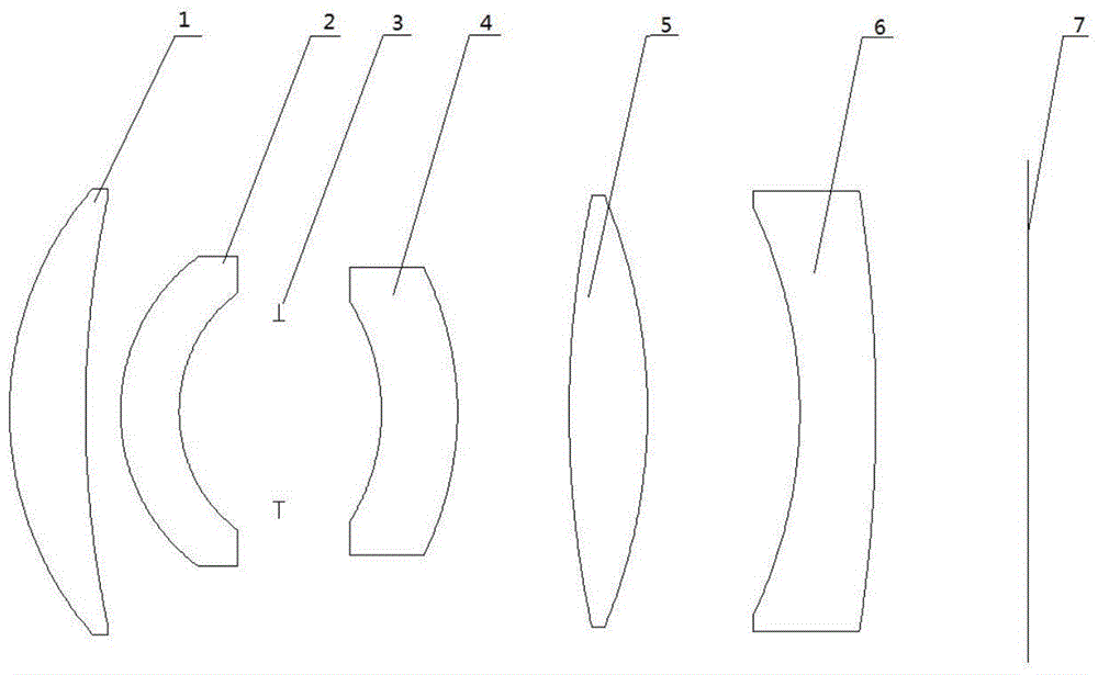
Referring to fig. 1, an optical sighting system, in order from an object side to an image side along an optical axis, includes:
the optical lens assembly comprises a first lens element 1 with positive refractive power, wherein the object-side surface of the first lens element 1 is convex, and the image-side surface thereof is concave;
a second lens element 2 with positive refractive power, wherein the object-side surface of the second lens element 2 is convex and the image-side surface thereof is concave;
a diaphragm 3;
a third lens element 4 with negative refractive power, wherein the object-side surface of the third lens element 4 is concave and the image-side surface thereof is convex;
a fourth lens element 5 with positive refractive power, wherein the object-side surface of the fourth lens element 5 is convex, and the image-side surface thereof is convex;
a fifth lens element 6 with negative refractive power, wherein the fifth lens element 6 has a concave object-side surface and a convex image-side surface;
an image plane 7.
The structure and material of the lens of the optical sighting system are shown in table 1 below.
TABLE 1 lens structure and material condition of optical aiming system
Note: the curvature radius is the curvature radius of the object side surface and/or the image side surface of the lens on the optical axis.
The thickness of the lens is the distance from the object side surface of the lens to the image side surface of the lens on the optical axis.
The air space represents a distance on the optical axis from the image-side surface of the preceding lens to the object-side surface of the subsequent lens.
The optical aiming system composed of the structure achieves the following optical indexes:
1. the total focal length is 15 mm;
2. half field angle is 16 °;
3. f is 3;
4. imaging spectrum is 800-860 nm;
5. the total length of the system is 18.11 mm;
6. the aiming range is 0.5m-100 m.
7. The Root Mean Square (RMS) diameter of the diffuse spot is less than or equal to 80 microns;
8. the offset of the diffuse speckle energy center is less than or equal to 4 microns;
9. the alignment accuracy is less than 1';
10. the maximum clear aperture is less than or equal to 10 mm.
Referring to fig. 2, the optical path of the optical sighting system is as follows: the point light source emitted by the target marker sequentially passes through the first lens 1, the second lens 2, the diaphragm 3, the third lens 4, the fourth lens 5 and the fifth lens 6 at different incidence angles to form an image on an image plane 7, and a light spot is formed.
The intensity distribution of the resulting spot is defined as the diffuse spot.
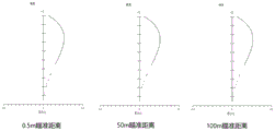
Fig. 3 is a dot array diagram of the diffuse spots formed by the optical sighting system according to the embodiment at sighting distances of 0.5m, 50m and 100m, respectively, and it can be seen from the diagram that the diffuse spots are approximately circular, have good roundness, and have substantially the same size, uniformity and symmetry, and the Root Mean Square (RMS) diameter of the light spot and the energy center offset of the corresponding detector meet the requirement of attitude measurement accuracy.
Fig. 4 is a distortion curve of the optical sighting system according to the present embodiment at sighting distances of 0.5m, 50m and 100m, respectively, and it can be seen that the relative distortion at each sighting distance is less than 0.1%.
Fig. 5 is an energy concentration curve of the centroids of the diffuse spots at the aiming distances of 0.5m, 50m and 100m for the optical aiming system of the present embodiment, and it can be seen from the graph that the energy concentration is greater than 90% in 90 micrometers and greater than 80% in 75 micrometers.