CN212303203U - Cable stranding machine - Google Patents
Cable stranding machine Download PDFInfo
- Publication number
- CN212303203U CN212303203U CN202021518856.5U CN202021518856U CN212303203U CN 212303203 U CN212303203 U CN 212303203U CN 202021518856 U CN202021518856 U CN 202021518856U CN 212303203 U CN212303203 U CN 212303203U
- Authority
- CN
- China
- Prior art keywords
- cable
- pressing
- driving motor
- stranding
- reel
- Prior art date
- Legal status (The legal status is an assumption and is not a legal conclusion. Google has not performed a legal analysis and makes no representation as to the accuracy of the status listed.)
- Active
Links
Images


Abstract
The utility model discloses a cable stranding machine, including bottom plate and hold-down mechanism, bottom plate surface one side is equipped with driving motor, driving motor top is equipped with the drawing drum, the drawing drum right-hand member is equipped with the cable reel, the drawing drum intermediate position is equipped with the pivot, the pivot right side is equipped with the mechanism of twisting with the hands, it is equipped with the stranding mechanism to rub with the hands, stranding mechanism one side is equipped with the hold-down mechanism, hold-down mechanism one side is equipped with the admission mechanism, pivot one end surface is equipped with the fixed block, the fixed block surface is equipped with the support, the threading hole has been seted up to the support upper surface, the hold-down mechanism surface is provided with the pressing seat, the pressing seat top is equipped with; the utility model has the advantages of conveniently adjust sinle silk transposition quantity, the transposition is even, transposition compact structure, degree of automation is high, improve product quality, easy operation, convenient to use.
Description
Technical Field
The utility model belongs to the technical field of the cable transposition technique and specifically relates to a cable stranding machine is related to.
Background
The stranding machine is a mechanical device widely applied to stranding production of various soft and hard conductor wires, and is mainly used for twisting a conductor cable with a plurality of single wires into one strand, so that certain wire process requirements are met, raw materials are provided for subsequent further processing production, in the manufacturing process of the cable, a stranding device is often used, the stranding device is used for stranding a plurality of single wires with the same diameter or different diameters together according to a certain direction and a certain rule to form an integral stranded wire, and in addition, the stranded wire core is more flexible than the single wire core with the same diameter, and the bending performance is better;
however, the twisting device is in the process of working, and the quantity requirement for the twisting of the wire cores is different according to different requirements, so that the twisting device is required to be adjusted, the twisting of the wire cores with different quantities is facilitated, and in addition, when a plurality of cables are twisted, the wire bundles are twisted into the wire bundles, so that the wire bundles are easy to wind, the problems of uneven winding and non-compact twisting of the wire cores of the conductors are also caused, the production efficiency of the wire twisting machine is influenced, the product quality of the wire cores of the conductors is reduced, and therefore, the cable twisting machine is provided.
SUMMERY OF THE UTILITY MODEL
The utility model aims at providing a cable stranding machine with conveniently adjust sinle silk transposition quantity, the transposition is even, transposition compact structure, degree of automation is high, improve product quality, easy operation, convenient to use, has solved the problem among the prior art.
The above utility model discloses an above-mentioned utility model purpose can realize through following technical scheme: the utility model provides a cable stranding machine, includes bottom plate and hold-down mechanism, its characterized in that: a driving motor is arranged on one side of the surface of the bottom plate, a pay-off reel is arranged above the driving motor, a cable drum is arranged at the right end of the pay-off reel, a rotating shaft is arranged in the middle of the pay-off reel, a wire twisting mechanism is arranged on the right side of the rotating shaft, a wire twisting mechanism is arranged on one side of the wire twisting mechanism, a pressing mechanism is arranged on one side of the wire twisting mechanism, and a wire collecting mechanism is arranged on one side of the pressing mechanism;
the utility model discloses a pressing mechanism, including pivot, fixed block, pinch roller, bearing, pivot one end surface is equipped with the fixed block, the fixed block surface is equipped with the support, the through wires hole has been seted up to the support upper surface, the hold-down mechanism surface is provided with compressing tightly the seat, the compressing tightly seat top is equipped with the compact heap, the compact heap inboard is equipped with the pinch.
The utility model discloses further set up to: the cable drum and the support are respectively provided with ten groups, the cable drum and the support are in one-to-one correspondence, and the cable drum is uniformly distributed in the center.
Through adopting above-mentioned technical scheme, through setting up multiunit cable drum, can satisfy the cable transposition of various specifications, can arrange in a flexible way in practical application and use.
The utility model discloses further set up to: the support inboard is equipped with the line wheel, the line wheel is provided with ten groups altogether.
Through adopting above-mentioned technical scheme, walk around the cable along the pulley through the through wires hole, reduce the frictional force of cable and through wires hole inner wall by a wide margin, further reduce the wearing and tearing of cable.
The utility model discloses further set up to: the retaining member is connected with the pressing block in a penetrating mode.
Through adopting above-mentioned technical scheme, adjust the cable transposition diameter of different specifications through the retaining member to make the pinch roller further compress tightly twisted cable, loose when avoiding the cable assembly to move, and then improve the compactness behind the cable transposition.
The utility model discloses further set up to: the inner sides of the pressing blocks are connected with pressing wheels through rotation, the pressing wheels are provided with two groups which are uniformly arranged in the vertical direction, and each pressing wheel is located between the inner walls of the pressing blocks.
Through adopting above-mentioned technical scheme, pass through setting up the pinch roller power supply cable, utilize the pinch roller to play and make the cable can laminate at the pinch roller inner wall after the transposition, and then realize drawing in of cable transposition, slow down the shearing force that the cable received, reduced the damage when cable transposition, improved the qualification degree of finished product cable, can play the effect of direction and location simultaneously, avoid the cable motion process to take place to rock or squint.
The utility model discloses further set up to: the drive motor input passes through the cable and connects external power source, the drive motor output is equipped with the transmission hinge, pass through transmission hinged joint between drive motor and the drawing drum.
Through adopting above-mentioned technical scheme, provide stable output power for whole device through driving motor, the moment transmission between driving motor and the drawing drum can be improved in the connection of transmission hinge.
To sum up, the utility model discloses a beneficial technological effect does:
1. when the cable stranding machine is used, structurally, after a cable core strand penetrates through a stranding mechanism, the strand of the cable core is preliminarily folded, a gap between the pressing wheels is adjusted by rotating the locking piece, the pressing wheels are utilized to enable a cable to be attached to the inner walls of the pressing wheels after the cable core strand is stranded, then the cable strand is folded, the shearing force borne by the cable is relieved, damage of the cable during stranding is reduced, the qualification degree of a finished cable is improved, meanwhile, the guide and positioning effects can be achieved, and shaking or deviation of the cable in the motion process is avoided;
2. the pay-off reel is used through the cooperation that adopts multiunit cable reel and line wheel, can match the quantity of the transposition of cable in a flexible way for stranded single strand cable keeps the straight line state before getting into the transposition, avoids single strand cable intertwine in the transposition in-process, produces harmful effects to the homogeneity of cable transposition, simple structure moreover.
Drawings
Fig. 1 is a schematic view of the overall structure of a cable stranding machine according to the present invention;
fig. 2 is a schematic front view of the cable stranding machine of the present invention;
fig. 3 is a schematic top view of the cable stranding machine according to the present invention;
fig. 4 is a schematic structural sectional view at the position B of the cable stranding machine of the present invention;
fig. 5 is an enlarged schematic view of a structure at a position a of the cable stranding machine of the present invention.
In the figure, 1, a bottom plate; 2. a drive motor; 3. a pay-off reel; 4. a cable drum; 5. a rotating shaft; 6. a thread twisting mechanism; 7. a wire stranding mechanism; 8. a hold-down mechanism; 9. a take-up mechanism; 10. a drive hinge; 11. a pinch roller; 12. a compression block; 13. a pressing seat; 14. a locking member; 15. a support; 16. threading holes; 17. a wire wheel; 18. and (5) fixing blocks.
Detailed Description
The technical solution in the embodiments of the present invention will be clearly and completely described below with reference to the drawings in the embodiments of the present invention, and it is obvious that the described embodiments are only some embodiments of the present invention, rather than all embodiments, and all other embodiments obtained by a person of ordinary skill in the art without creative work belong to the protection scope of the present invention based on the embodiments of the present invention.
In the description of the present invention, it is to be understood that the terms "upper", "lower", "front", "rear", "left", "right", "top", "bottom", "inner", "outer", and the like indicate orientations or positional relationships based on the orientations or positional relationships shown in the drawings, and are only for convenience of description and simplicity of description, and do not indicate or imply that the device or element being referred to must have a particular orientation, be constructed and operated in a particular orientation, and therefore, should not be construed as limiting the present invention.
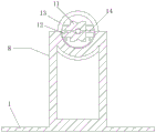
Referring to fig. 1 and 2, in order to disclose a cable stranding machine, the cable stranding machine comprises a bottom plate 1 and a pressing mechanism 8, a driving motor 2 is arranged on one side of the surface of the bottom plate 1, an output end of the driving motor 2 is provided with a transmission hinge 10, the driving motor 2 is connected with a pay-off reel 3 through the transmission hinge 10, the pay-off reel 3 is arranged above the driving motor 2, a cable reel 4 is arranged at the right end of the pay-off reel 3, a rotating shaft 5 is arranged at the middle position of the pay-off reel 3, a fixed block 18 is arranged on the surface of one end of the rotating shaft 5, a support 15 is arranged on the surface of the fixed block 18, a threading hole 16 is formed in the upper surface of the support;
in this embodiment, firstly, the external power source is connected through the cable to the input end of driving motor 2, provide stable operation power for whole device, start driving motor 2, driving motor 2 drives drawing drum 3 through transmission hinge 10 and rotates, place a certain amount of cable reel 4 on the drum according to actual production demand, fixed block 18 plays the effect of installing support 15, be convenient for pass through wires hole 16 with the cable core, draw out along pivot 5 direction on line wheel 17, drawing drum 3 drives pivot 5 motion, pass and tighten up the cable preliminarily with rubbing by wire mechanism 6, do the circular motion along pivot 5 direction simultaneously, the cable conductor twists the cable through stranding mechanism 7 and tightens up, in practical application, also can change the arrangement mode and the arrangement quantity of drawing drum 3 and cable reel 4 according to actual need, do not specifically limit here.
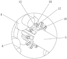
As shown in fig. 2 and 4, a pressing mechanism 8 is arranged on one side of the wire twisting mechanism 7, a pressing base 13 is arranged on the surface of the pressing mechanism 8, a pressing block 12 is arranged above the pressing base 13, a pressing wheel 11 is arranged on the inner side of the pressing block 12, locking pieces 14 are arranged on two sides of the pressing wheel 11, and a wire rewinding mechanism 9 is arranged on one side of the pressing mechanism 8;
in this embodiment, hold-down mechanism 8 top is equipped with compressing tightly seat 13, compressing tightly seat 13 and stranding mechanism 7's axis are on same straight line, retaining member 14 through connection compact heap 12 is used for adjusting the transposition cable diameter that is compressed tightly, adjust the clearance between the pinch roller 11 through rotating retaining member 14, utilize pinch roller 11 to play and make the cable can laminate at pinch roller 11 inner wall after the transposition, and then realize drawing in of cable transposition, slow down the shearing force that the cable received, damage when having reduced the cable transposition, the qualification degree of finished cable has been improved, can play the effect of direction and location simultaneously, avoid the cable motion process to take place to rock or squint, cable after will twisting through admission machine 9 carries out the roll-up and deposits, the utility model discloses simple structure, the practicality is strong.
Referring to fig. 1, cable reel 4 and support 15 are provided with ten groups respectively, and one-to-one between cable reel 4 and the support 15, and cable reel 4 is central evenly distributed, through setting up multiunit cable reel 4, can satisfy the cable transposition of various specifications, can arrange in a flexible way in practical application and use.
Referring to fig. 5, the inner side of the bracket 15 is provided with the wire wheels 17, the wire wheels 17 are provided with ten groups, the cable is wound around the pulley through the wire through hole 16, the friction force between the cable and the inner wall of the wire through hole 16 is greatly reduced, and the abrasion of the cable is further reduced.
Referring to fig. 4, the locking member 14 penetrates through the pressing block 12, and the twisting diameters of cables of different specifications are adjusted through the locking member 14, so that the pressing wheel 11 further presses the twisted cable, the cable group is prevented from loosening during movement, and the tightness of the twisted cable is improved.
Referring to fig. 3 and 4, the inboard of compact heap 12 is connected with pinch roller 11 through rotating, pinch roller 11 is provided with two sets of evenly arranged in vertical direction altogether, every pinch roller 11 all is located between 12 inner walls of compact heap, supply the cable to pass through setting up pinch roller 11, utilize pinch roller 11 to play and make the cable can laminate at pinch roller 11 inner wall after the transposition, and then realize drawing in of cable transposition, the shearing force that slows down the cable and receive, the damage when having reduced the cable transposition, the qualification degree of finished cable has been improved, can play the effect of direction and location simultaneously, avoid the cable motion process to take place to rock or squint.
Referring to fig. 2 and 3, the input end of the driving motor 2 is connected with an external power supply through a cable, the output end of the driving motor 2 is provided with a transmission hinge 10, the driving motor 2 is connected with the pay-off reel 3 through the transmission hinge 10, stable output power is provided for the whole device through the driving motor 2, and the connection of the transmission hinge 10 can improve the torque transmission between the driving motor 2 and the pay-off reel 3.
The implementation principle of the embodiment is as follows:
the utility model relates to a cable stranding machine, firstly, the input end of a driving motor 2 is connected with an external power supply through a cable to provide stable operation power for the whole device, the driving motor 2 is started, the driving motor 2 drives a pay-off reel 3 to rotate through a transmission hinge 10, a certain number of cable reels 4 are placed on the pay-off reel according to actual production requirements, a fixed block 18 plays the role of a mounting bracket 15 to facilitate the cable core to pass through a threading hole 16, the cable core is drawn out along the direction of a rotating shaft 5 on a reel 17, the pay-off reel 3 drives the rotating shaft 5 to move, the cable is primarily tightened through a thread twisting mechanism 6 and does circular motion along the direction of the rotating shaft 5, the cable is twisted and tightened through a thread twisting mechanism 7, a pressing seat 13 is assembled above the pressing mechanism 8, the pressing seat 13 and the axis of the thread twisting mechanism 7 are on the same straight line, a locking piece 14 is penetratingly connected with a pressing, adjust the clearance between the pinch roller 11 through rotating retaining member 14, utilize pinch roller 11 to play and make the cable can laminate at pinch roller 11 inner wall after the transposition, and then realize drawing in of cable transposition, the shearing force that slows down the cable and receives, damage when having reduced the cable transposition, the qualification degree of finished cable has been improved, can play the effect of direction and location simultaneously, avoid the cable motion process to take place to rock or squint, the cable after will twisting is rolled up through admission machine 9 and is deposited, in order to solve the technical problem who exists among the prior art.
Having shown and described the basic principles and principal features of the invention and advantages thereof, it will be apparent to those skilled in the art that the invention is not limited to the details of the foregoing exemplary embodiments, but is capable of other specific forms without departing from the spirit or essential characteristics thereof; the present embodiments are therefore to be considered in all respects as illustrative and not restrictive, the scope of the invention being indicated by the appended claims rather than by the foregoing description, and all changes which come within the meaning and range of equivalency of the claims are therefore intended to be embraced therein, and any reference signs in the claims are not intended to be construed as limiting the claim concerned.
Furthermore, it should be understood that although the present description refers to embodiments, not every embodiment may contain only a single embodiment, and such description is for clarity only, and those skilled in the art should integrate the description, and the embodiments may be combined as appropriate to form other embodiments understood by those skilled in the art.
Claims (6)
1. The utility model provides a cable stranding machine, includes bottom plate (1) and hold-down mechanism (8), its characterized in that: a driving motor (2) is arranged on one side of the surface of the bottom plate (1), a pay-off reel (3) is arranged above the driving motor (2), a cable drum (4) is arranged at the right end of the pay-off reel (3), a rotating shaft (5) is arranged in the middle of the pay-off reel (3), a wire twisting mechanism (6) is arranged on the right side of the rotating shaft (5), a wire twisting mechanism (7) is arranged on one side of the wire twisting mechanism (6), a pressing mechanism (8) is arranged on one side of the wire twisting mechanism (7), and a wire collecting mechanism (9) is arranged on one side of the pressing mechanism (8);
pivot (5) one end surface is equipped with fixed block (18), fixed block (18) surface is equipped with support (15), through wires hole (16) have been seted up to support (15) upper surface, hold-down mechanism (8) surface is provided with compressing tightly seat (13), compressing tightly seat (13) top is equipped with compact heap (12), compact heap (12) inboard is equipped with pinch roller (11), pinch roller (11) both sides are equipped with retaining member (14).
2. A machine for stranding cables according to claim 1, characterized in that: the cable drum (4) and the support (15) are respectively provided with ten groups, the cable drum (4) and the support (15) are in one-to-one correspondence, and the cable drum (4) is uniformly distributed in the center.
3. A machine for stranding cables according to claim 1, characterized in that: the inner side of the support (15) is provided with wire wheels (17), and the wire wheels (17) are provided with ten groups.
4. A machine for stranding cables according to claim 1, characterized in that: the locking piece (14) is connected with the pressing block (12) in a penetrating way.
5. A machine for stranding cables according to claim 1, characterized in that: the inner sides of the pressing blocks (12) are connected with pressing wheels (11) through rotation, the pressing wheels (11) are provided with two groups which are uniformly arranged in the vertical direction, and each pressing wheel (11) is located between the inner walls of the pressing blocks (12).
6. A machine for stranding cables according to claim 1, characterized in that: the input end of the driving motor (2) is connected with an external power supply through a cable, the output end of the driving motor (2) is provided with a transmission hinge (10), and the driving motor (2) is connected with the pay-off reel (3) through the transmission hinge (10).
Priority Applications (1)
| Application Number | Priority Date | Filing Date | Title |
|---|---|---|---|
| CN202021518856.5U CN212303203U (en) | 2020-07-28 | 2020-07-28 | Cable stranding machine |
Applications Claiming Priority (1)
| Application Number | Priority Date | Filing Date | Title |
|---|---|---|---|
| CN202021518856.5U CN212303203U (en) | 2020-07-28 | 2020-07-28 | Cable stranding machine |
Publications (1)
| Publication Number | Publication Date |
|---|---|
| CN212303203U true CN212303203U (en) | 2021-01-05 |
Family
ID=73937797
Family Applications (1)
| Application Number | Title | Priority Date | Filing Date |
|---|---|---|---|
| CN202021518856.5U Active CN212303203U (en) | 2020-07-28 | 2020-07-28 | Cable stranding machine |
Country Status (1)
| Country | Link |
|---|---|
| CN (1) | CN212303203U (en) |
Cited By (6)
| Publication number | Priority date | Publication date | Assignee | Title |
|---|---|---|---|---|
| CN112589697A (en) * | 2021-01-06 | 2021-04-02 | 李乔 | Novel stranding device for composite metal consolidation abrasive diamond rope |
| CN113130142A (en) * | 2021-06-17 | 2021-07-16 | 新沂市中振电器科技有限公司 | Automatic processing equipment and processing technology for production and manufacturing of wires and cables |
| CN113963860A (en) * | 2021-12-23 | 2022-01-21 | 深圳市方泰设备技术有限公司 | Automatic stranding equipment for wires |
| CN114267494A (en) * | 2021-12-10 | 2022-04-01 | 江苏浦漕科技股份有限公司 | Aluminum alloy flexible photovoltaic cable stranding equipment and stranding method thereof |
| CN116289279A (en) * | 2023-03-14 | 2023-06-23 | 张家港新华预应力钢绞线有限公司 | Production equipment for high-strength prestressed steel strand |
| CN116364355A (en) * | 2023-05-04 | 2023-06-30 | 武汉武湖电缆有限公司 | Copper wire stranded wire structure for cable forming and stranded wire method |
-
2020
- 2020-07-28 CN CN202021518856.5U patent/CN212303203U/en active Active
Cited By (12)
| Publication number | Priority date | Publication date | Assignee | Title |
|---|---|---|---|---|
| CN112589697A (en) * | 2021-01-06 | 2021-04-02 | 李乔 | Novel stranding device for composite metal consolidation abrasive diamond rope |
| CN112589697B (en) * | 2021-01-06 | 2021-07-09 | 李乔 | Novel stranding device for composite metal consolidation abrasive diamond rope |
| CN113130142A (en) * | 2021-06-17 | 2021-07-16 | 新沂市中振电器科技有限公司 | Automatic processing equipment and processing technology for production and manufacturing of wires and cables |
| CN113130142B (en) * | 2021-06-17 | 2021-08-17 | 新沂市中振电器科技有限公司 | Automatic processing equipment and processing technology for production and manufacturing of wires and cables |
| CN114267494A (en) * | 2021-12-10 | 2022-04-01 | 江苏浦漕科技股份有限公司 | Aluminum alloy flexible photovoltaic cable stranding equipment and stranding method thereof |
| CN114267494B (en) * | 2021-12-10 | 2022-11-01 | 江苏浦漕科技股份有限公司 | Aluminum alloy flexible photovoltaic cable stranding equipment and stranding method thereof |
| CN113963860A (en) * | 2021-12-23 | 2022-01-21 | 深圳市方泰设备技术有限公司 | Automatic stranding equipment for wires |
| CN113963860B (en) * | 2021-12-23 | 2022-03-22 | 深圳市方泰设备技术有限公司 | Automatic stranding equipment for wires |
| CN116289279A (en) * | 2023-03-14 | 2023-06-23 | 张家港新华预应力钢绞线有限公司 | Production equipment for high-strength prestressed steel strand |
| CN116289279B (en) * | 2023-03-14 | 2023-11-21 | 张家港新华预应力钢绞线有限公司 | Production equipment for high-strength prestressed steel strand |
| CN116364355A (en) * | 2023-05-04 | 2023-06-30 | 武汉武湖电缆有限公司 | Copper wire stranded wire structure for cable forming and stranded wire method |
| CN116364355B (en) * | 2023-05-04 | 2023-08-15 | 武汉武湖电缆有限公司 | Copper wire stranded wire structure for cable forming and stranded wire method |
Similar Documents
| Publication | Publication Date | Title |
|---|---|---|
| CN212303203U (en) | Cable stranding machine | |
| CN212303204U (en) | Cable production stranded conductor device | |
| CN213595588U (en) | Wire paying-off, twisting and winding device | |
| CN220106122U (en) | Cable core stranding machine | |
| CN217690635U (en) | Stranding machine for power cable | |
| CN218886899U (en) | Bidirectional stranded wire production line | |
| CN114628087B (en) | Winding and coiling machine for compound stranded wire | |
| CN217239150U (en) | Get high-speed stranding machine of material clamping synchronous drive | |
| CN216957570U (en) | Novel cable-former for processing cable and wire | |
| CN216528220U (en) | Twisting device for cable manufacturing | |
| CN209591665U (en) | A kind of four times of stranding machines | |
| CN111863355B (en) | Wire twisting machine for cable manufacturing | |
| CN211687736U (en) | Cabling machine coiling mechanism for cable preparation | |
| CN208538562U (en) | Strand type carbon fiber complex core disc type stranding machine | |
| CN111705382A (en) | Twisting method of efficient double-twisting stranding machine | |
| CN220324231U (en) | Wire twisting machine for wire and cable processing | |
| CN117163757B (en) | Stranded cable apparatus for producing | |
| CN219842838U (en) | High-efficient cabling device is used in cable production | |
| CN220189322U (en) | Wire twisting machine for cable preparation | |
| JPH0821274B2 (en) | Production equipment for compressed strand conductors | |
| CN117059331B (en) | Stranded wire equipment for producing wires and cables | |
| CN213424715U (en) | Stranded wire stranding device | |
| CN219832301U (en) | Wire and cable stranded wire equipment | |
| CN214847928U (en) | High-efficiency three-core back-twist twisting machine | |
| CN218022341U (en) | Bundling device is used in fire resisting cable production |
Legal Events
| Date | Code | Title | Description |
|---|---|---|---|
| GR01 | Patent grant | ||
| GR01 | Patent grant |