CN212286822U - Hydraulic gripper clamp - Google Patents
Hydraulic gripper clamp Download PDFInfo
- Publication number
- CN212286822U CN212286822U CN202021950368.1U CN202021950368U CN212286822U CN 212286822 U CN212286822 U CN 212286822U CN 202021950368 U CN202021950368 U CN 202021950368U CN 212286822 U CN212286822 U CN 212286822U
- Authority
- CN
- China
- Prior art keywords
- gripper
- ball
- hydraulic
- base
- vertical support
- Prior art date
- Legal status (The legal status is an assumption and is not a legal conclusion. Google has not performed a legal analysis and makes no representation as to the accuracy of the status listed.)
- Active
Links
Images


Abstract
The utility model belongs to the technical field of milling machine, drilling machine processing, especially, relate to a hydraulic pressure grab ball anchor clamps, its characterized in that includes the base, sets up the vertical support on this base, and with the pneumatic cylinder that this vertical support threaded connection and level set up, the arc ball tongs that is connected with the flexible end of this pneumatic cylinder, vertical support includes upper portion threaded connection head, lower part sliding chute pole and adjusting bolt, and the lower part sliding chute pole inserts just by adjusting bolt is fixed in the slide of base. The utility model can process the ball body on a milling machine and a drilling machine, thereby reducing the cost; the hydraulic gripper clamp comprises a lifting device, a hydraulic device and a gripper, the gripper is pushed to advance by a small hydraulic cylinder and applies gripping force, and the arc gripper is used for clamping a ball body.
Description
Technical Field
The utility model belongs to the technical field of milling machine, drilling machine processing, especially, relate to a ball anchor clamps are grabbed to hydraulic pressure.
Background
In the prior art, a lathe is generally used for machining a sphere, small and medium-sized enterprises cannot take out a large amount of funds to purchase a machine tool in production and transformation, transformation and machining can be performed only on the basis of an original machine tool, and the sphere is machined by using a milling machine and a drilling machine, so that the cost can be greatly saved, the burden of the enterprises is reduced, and the enterprises can use less funds to upgrade the industry. However, when the ball is machined by a milling machine or a drilling machine, the ball is generally clamped by a mechanical structure, which is inconvenient to assemble and disassemble and complicated in operation steps.
Disclosure of Invention
The utility model aims at overcoming not enough among the prior art, providing a ball anchor clamps are grabbed to hydraulic pressure, can effectively utilize current milling machine and drilling machine to the spheroid processing of adaptation milling machine and drilling machine.
The purpose of the utility model is realized by the following technical scheme:
the utility model is characterized in that the hydraulic gripper clamp comprises a base, a vertical support arranged on the base, a hydraulic cylinder which is connected with the vertical support by screw thread and is arranged horizontally, and an arc ball gripper which is connected with the telescopic end of the hydraulic cylinder,
the vertical support include upper portion threaded connection head, lower part spout pole and adjusting bolt, lower part spout pole insert in the slide of base and fixed by adjusting bolt.
The radian of the arc-shaped ball gripper is matched with the radian of a ball body to be processed.
The utility model has the advantages that:
the hydraulic claw ball clamp of the utility model can process the ball body on a milling machine and a drilling machine, thereby reducing the cost; the hydraulic gripper clamp comprises a lifting device, a hydraulic device and a gripper, the gripper is pushed to advance by a small hydraulic cylinder and applies gripping force, and the arc gripper is used for clamping a ball body.
Drawings
Fig. 1 is a schematic structural diagram of the present invention.
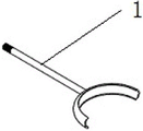
Fig. 2 is a schematic structural view of the arc-shaped ball gripper of the present invention.
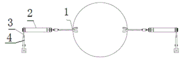
Fig. 3 is a schematic structural diagram of the hydraulic cylinder of the present invention.
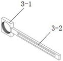
Fig. 4 is a schematic structural diagram of the bracket of the present invention.
Fig. 5 is a schematic structural diagram of the base of the present invention.
Fig. 6 is a working state diagram of the present invention.
Detailed Description
The following further describes the embodiments of the present invention with reference to the drawings.
As shown in fig. 1-6, the hydraulic gripper clamp of the present invention is characterized by comprising a base 4, a vertical support 3 disposed on the base 4, a hydraulic cylinder 2 connected with the vertical support 3 by screw thread and horizontally disposed, an arc ball gripper 1 connected with the telescopic end of the hydraulic cylinder 2,
the vertical support 3 comprises an upper threaded connector 3-1, a lower sliding groove rod 3-2 and an adjusting bolt 3-3, and the lower sliding groove rod 3-2 is inserted into the sliding way of the base 4 and is fixed by the adjusting bolt 3-3.
The utility model discloses a hydraulic pressure tongs anchor clamps relates to the anchor clamps on milling machine and drilling machine, including pneumatic cylinder 2, arc ball tongs 1, support 3, base 4. The support 3 and the base 4 are connected through an adjusting bolt 3-3 to form a lifting device, a lower sliding groove rod 3-2 is inserted into a sliding way of the base 4, and the adjusting bolt 3-3 controls the vertical movement to select the height position of the support 3; the support 3 and the hydraulic cylinder 2 are connected through threads to play a supporting role, so that the disassembly is convenient, and better replaceability is realized when the ball body faces different sizes; the hydraulic cylinder 2 and the arc-shaped ball gripper 1 form a clamping device, and the arc-shaped ball gripper 1 clamps the ball body by using the pressure of the hydraulic cylinder 2 to clamp the ball body. When the hydraulic ball gripper clamp is used for clamping a ball, the height of the arc-shaped ball gripper 1 is adjusted through the support 3, when the height is appropriate, the position of the support 3 is locked through the adjusting bolts 3-3, the hydraulic cylinder 2 supplies oil to enable the arc-shaped ball gripper 1 to approach the ball, and the arc-shaped ball gripper 1 grips the upper side and the lower side of the center line of the ball. The ball body is locked by the pressure of the hydraulic cylinder 2, so that the ball body cannot rotate and move, and after the machining is finished, the hydraulic cylinder 2 enables the arc-shaped ball gripper 1 to retract, so that the clamping task is finished.
The hydraulic claw ball clamp of the utility model can process the ball body on a milling machine and a drilling machine, thereby reducing the cost; the hydraulic gripper clamp comprises a lifting device, a hydraulic device and a gripper, the gripper is pushed to advance by a small hydraulic cylinder and applies gripping force, and the arc-shaped ball gripper 1 is used for clamping a ball body.
Claims (2)
1. A hydraulic gripper clamp is characterized by comprising a base, a vertical support arranged on the base, a hydraulic cylinder which is in threaded connection with the vertical support and is horizontally arranged, and an arc-shaped ball gripper connected with the telescopic end of the hydraulic cylinder,
the vertical support include upper portion threaded connection head, lower part spout pole and adjusting bolt, lower part spout pole insert in the slide of base and fixed by adjusting bolt.
2. A hydraulic grasper clamp as claimed in claim 1, wherein the curvature of the curved ball grasper is adapted to the curvature of the ball to be worked.
Priority Applications (1)
| Application Number | Priority Date | Filing Date | Title |
|---|---|---|---|
| CN202021950368.1U CN212286822U (en) | 2020-09-09 | 2020-09-09 | Hydraulic gripper clamp |
Applications Claiming Priority (1)
| Application Number | Priority Date | Filing Date | Title |
|---|---|---|---|
| CN202021950368.1U CN212286822U (en) | 2020-09-09 | 2020-09-09 | Hydraulic gripper clamp |
Publications (1)
| Publication Number | Publication Date |
|---|---|
| CN212286822U true CN212286822U (en) | 2021-01-05 |
Family
ID=73934274
Family Applications (1)
| Application Number | Title | Priority Date | Filing Date |
|---|---|---|---|
| CN202021950368.1U Active CN212286822U (en) | 2020-09-09 | 2020-09-09 | Hydraulic gripper clamp |
Country Status (1)
| Country | Link |
|---|---|
| CN (1) | CN212286822U (en) |
-
2020
- 2020-09-09 CN CN202021950368.1U patent/CN212286822U/en active Active
Similar Documents
| Publication | Publication Date | Title |
|---|---|---|
| CN110480542B (en) | Overturning positioning supporting tool system | |
| CN204975993U (en) | Turnning and milling all -in -one | |
| CN212886313U (en) | Clamp combination for numerical control machining | |
| CN104209857A (en) | Workpiece clamping device and workpiece clamping method for cylindrical grinding machine | |
| CN212286822U (en) | Hydraulic gripper clamp | |
| CN201702472U (en) | Pneumatic suspension tapping machine | |
| CN207431816U (en) | A kind of golf club head clamping fixture | |
| CN211761632U (en) | Pneumatic clamping jaw mechanism for liquefied gas steel cylinder | |
| CN111906572A (en) | Hydraulic gripper clamp | |
| CN208729244U (en) | A kind of precise clamp | |
| CN106736731A (en) | A kind of clamping tool of splined driveshaft yoke | |
| CN201579611U (en) | Motorcycle shock absorber drill jig | |
| CN212311489U (en) | Angular positioning fixture | |
| CN211162683U (en) | Welding fixture for manufacturing oil cylinder | |
| CN210024536U (en) | Machining center anchor clamps | |
| CN209970225U (en) | Auxiliary tool for machining cylinder valve body | |
| CN206405763U (en) | A kind of bench vice of machine tooling clamping fastener | |
| CN112157277A (en) | Automatic feeding and positioning device for pump shaft of axial flow pump | |
| CN216882706U (en) | Special fixture for machining spindle box | |
| CN205928694U (en) | Feeding mechanical arm anchor clamps of left back door | |
| CN202336764U (en) | Rapid automatic feeding mechanism of crankshaft rolling tool | |
| CN220449550U (en) | Lifting appliance for concrete prefabricated part | |
| CN207593329U (en) | A kind of radial drilling machine workbench Workpiece clamping device | |
| CN203993204U (en) | A kind of large-size cylinder body use for machining parts auxiliary clamp | |
| CN207629105U (en) | The adjustable forging fixture of one kind |
Legal Events
| Date | Code | Title | Description |
|---|---|---|---|
| GR01 | Patent grant | ||
| GR01 | Patent grant |