CN212311489U - Angular positioning fixture - Google Patents
Angular positioning fixture Download PDFInfo
- Publication number
- CN212311489U CN212311489U CN202021491190.9U CN202021491190U CN212311489U CN 212311489 U CN212311489 U CN 212311489U CN 202021491190 U CN202021491190 U CN 202021491190U CN 212311489 U CN212311489 U CN 212311489U
- Authority
- CN
- China
- Prior art keywords
- push
- push rod
- angular
- angular positioning
- jaw seat
- Prior art date
- Legal status (The legal status is an assumption and is not a legal conclusion. Google has not performed a legal analysis and makes no representation as to the accuracy of the status listed.)
- Active
Links
Images

Abstract
An angular positioning fixture is mainly used for positioning the angular direction of a crankshaft. The floating center is connected with an oil cylinder pull rod through a push disc body, a rectangular compression spring is arranged between the floating center and the push disc body, a fixture is connected with an oil cylinder piston rod through the pull rod, the pull rod is connected with the push disc body, a push disc is arranged on the push disc body, the push disc is clamped in clamping grooves at one ends of a lower push rod, a left push rod, a right push rod and an angular push rod respectively, a push disc compression spring is arranged between the push disc and a locking nut locked on the push disc body, and wedge-shaped surfaces at the other ends of the push rod and the angular push rod are matched with wedge-shaped inclined surfaces of a clamping jaw seat and a sliding. The utility model discloses have angular positioning function, can closely press from both sides tight location with reliable to the angular of work piece, degree of automation and flexibility are very high, operation process safe and reliable can effectively improve the machining precision of work piece, alleviates operating personnel's intensity of labour. The positioning device is mainly applied to clamping the crankshaft journal and positioning the angular positioning surface of the crankshaft journal.
Description
Technical Field
The utility model relates to an automobile parts makes technical field, specifically is an angular positioning fixture for processing bent axle main shaft neck, connecting rod neck and main even journal balancing piece terminal surface.
Background
The crankshaft structure generally consists of a main journal, a connecting rod journal, a crank arm, a balance block, a large end and a small end. A certain eccentricity exists between a main journal and a connecting rod journal of the crankshaft, and the processing is very troublesome for a common machine tool. The common lathe can only process the main journal, but the connecting rod journal with the eccentricity and the two sides of the balance weight are difficult to process on the common lathe, if the common lathe is adopted for processing, a heavy special clamp must be manufactured, and the installation and the use are very troublesome. The processing of the main journal and the connecting rod journal of the crankshaft and the end surface of the main connecting journal balancing block can also use an imported internal milling machine tool, but the imported machine tool has the following defects:
1. and (5) aging the machine tool.
2. Because the size range of each variety of crankshafts is large, the types are multiple, the model change is frequent, the imported machine tool cannot meet the development requirement of new products, and the imported machine tool is designed according to the original crankshaft structure, so that the flexibility degree is very low.
3. The price is expensive, and if a production line is newly added, the imported machine tool needs to be purchased again, so that the production cost is very high.
4. The key accessories of the imported machine tool cannot be purchased at home, the replacement is inconvenient, the maintenance needs to ask for foreign experts, the period is long, and the cost is high.
Combining the current situation of crankshaft processing, automatic processing equipment for the main connecting shaft neck and the balance block end face of the crankshaft is produced, and the cutting positions of the cutter head of the equipment in the transverse direction, the vertical direction and the vertical direction are controlled by a CNC control system. Before the crankshaft is clamped, the excircles at two ends of the crankshaft fall on auxiliary supports on axial positioning fixtures at two ends, pull rods on the axial positioning fixtures drive floating center tips to extend forwards to prop against small end tip holes, so that the crankshaft moves leftwards to enable the end face of the large end of the crankshaft to lean against an axial positioning stop block on the axial positioning fixtures to complete axial positioning, push discs in the axial positioning fixtures at two ends drive the jaws to complete automatic clamping of the excircle of the large end of the crankshaft and the excircle of a main journal at the small end of the crankshaft, the crankshaft starts to be processed after being clamped, a left cutter disc and a right cutter disc stop at designated positions, only the right cutter disc rotates and feeds to cut the main journal M; and the left cutter head, the center frame and the right cutter head are moved to processing positions, the center frame is folded to clamp the processed main journal M2, the left cutter head and the right cutter head are simultaneously processed, and a connecting journal, a main journal and a main connecting journal balance block end face are sequentially processed at one time.
The existing axial positioning clamp cannot accurately position the angular direction of the crankshaft. When the cutter head is used for processing the connecting rod neck, if the angular position of the connecting rod neck is not positioned, the cutter head cannot be used for accurately finding the processing center of the connecting rod neck, and the connecting rod neck cannot be processed. In addition, in the machining process, the radial cutting force of a cutter on the crankshaft is very large, and the crankshaft is clamped by three clamping jaws at two ends, so that the crankshaft rotates on the clamping jaws due to slipping caused by the radial cutting force. Angular positioning may act to resist radial forces. Therefore, it is very important to develop an angular positioning fixture capable of reliably positioning the crankshaft in an angular direction.
Disclosure of Invention
In order to overcome the defects of the prior art, the invention aims to provide an angular positioning fixture to realize the automatic positioning of the workpiece in an angular direction.
In order to realize the purpose, the floating center is arranged in the fixture body of the angular positioning fixture, the floating center is connected with the pull rod of the oil cylinder through the push disc body, and a rectangular compression spring is arranged between the floating center and the push disc body; the oil cylinder is arranged on a bracket, and the bracket is provided with two contactless switches and corresponding shaking blocks which can send out clamping and loosening signals for clamping a workpiece by the angular positioning fixture; the angular positioning fixture is connected with a piston rod of an oil cylinder through a pull rod, the pull rod is connected with a push disc body, a push disc is arranged on the push disc body, the push disc is clamped in clamping grooves at one ends of a lower push rod, a left push rod, a right push rod and an angular push rod respectively, a push disc compression spring is arranged between the push disc and a locking nut locked on the push disc body, wedge-shaped surfaces at the other ends of the lower push rod, the left push rod, the right push rod and the angular push rod are matched with wedge-shaped inclined surfaces of a lower jaw seat II, a left jaw seat I, a right jaw seat I and a sliding block respectively, the piston rod of the oil cylinder moves, the lower push rod, the left push rod, the right push rod and two angular push rods are driven by the push disc, the lower push rod, the lower jaw seat II, the left push rod, the left jaw seat I, the right push rod, and the, The radial motion of the three clamping jaws on the left clamping jaw seat I and the right clamping jaw seat I and the radial motion of the two angular positioning clamping jaws on the sliding block realize the clamping or loosening of the angular positioning surfaces of the workpiece by the three clamping jaws after the inner hexagonal cylindrical end fastening screw on the angular positioning device clamps or loosens the angular positioning surfaces of the workpiece.
An opening is cut at the upper end of one jaw seat, and the opening distance K of the jaw seat in a non-clamping state is larger than the diameter of a workpiece; the clamping precision of the clamping jaw is adjusted by adjusting pads arranged between a first clamping jaw seat and a second clamping jaw seat on the angular positioning clamping apparatus and the clamping jaw; the angular positioning fixture injects oil into the fixture body through the straight-through type pressure injection oil cup on the fixture body; the angular positioning fixture is provided with a blowing structure, the air pipe is connected to the fixture body through a hose by a pneumatic triple piece, the air pipe blows air into the fixture body when the workpiece is loosened, and part of scrap iron remained on the fixture body is blown off by the air.
Two auxiliary supports are symmetrically arranged below the angular positioning fixture.
Compared with the prior art, the utility model, angular positioning fixture has angular positioning function for hydraulic pressure three-jaw is from centering fixture, can carry out the precision and reliably press from both sides tight location to the angle of work piece, and degree of automation and flexibility are very high, and operation process safe and reliable can effectively improve the machining precision of work piece, alleviates operating personnel's intensity of labour. The crankshaft journal clamping device is mainly used for clamping crankshaft journals and positioning angular positioning surfaces of the crankshaft journals.
Drawings
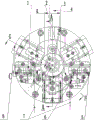
Fig. 1 is a schematic view of the present invention.
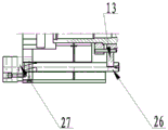
Fig. 2 is a sectional view a-a of fig. 1.
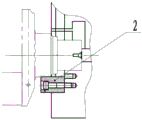
Fig. 3 is a C-C rotated view of fig. 1.
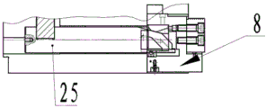
Fig. 4 is a view of fig. 1 rotated at F-F.
Fig. 5 is a G-G rotation view of fig. 1.
In the figure: 1. an angular positioning jaw; 2. auxiliary supporting; 3. a claw; 4. an opening distance K; 5. a straight-through type pressure injection oil cup; 6. a set screw is fastened at the end of the inner hexagonal cylinder; 7. an angular positioning surface; 8. a first clamping jaw seat; 9. a second jaw seat; 10. an adjustment pad; 11. a floating center; 12. a card body; 13. pushing the disc; 14. a clamp spigot; 15. a rectangular compression spring; 16. a pneumatic triplet; 17. the push disc compresses the spring; 18. a lower push rod; 19. a tray pushing body; 20. a pull rod; 21. an oil cylinder; 22. shaking blocks; 23. a support; 24. a contactless switch; 25. a push rod; 26. an angular push rod; 27. a slider; 28. an angular positioning fixture.
Detailed Description
As shown in fig. 1, fig. 2, fig. 3, fig. 4, and fig. 5, the angular positioning fixture 28 of the present invention is a hydraulic three-jaw self-centering fixture, which is mainly used for clamping the crankshaft journal and positioning the angular positioning surface 7 thereof, and the angular positioning fixture 28 can be installed in place through the fixture seam allowance 14 and the movable support. A floating center 11 is arranged in the clamp body 12, the floating center 11 is connected with a pull rod 20 of an oil cylinder 21 through a push disc body 19, and a rectangular compression spring 15 is arranged between the floating center 11 and the push disc body 19; the oil cylinder 21 is arranged on a bracket 23, and the bracket 23 is provided with two non-contact switches 24 and a shaking block 22 which can send out clamping and releasing signals for clamping a crankshaft main journal by an angular positioning clamp 28; the angular positioning fixture 28 is connected with a piston rod of an oil cylinder 21 through a pull rod 20, the pull rod 20 is connected with a push disc body 19, a push disc 13 is arranged on the push disc body 19, the push disc 13 is respectively clamped in clamping grooves at one ends of a lower push rod 18, a left push rod 25, a right push rod 25 and an angular push rod 26, a push disc compression spring 17 is arranged between the push disc 13 and a locking nut locked on the push disc body 19, wedge-shaped surfaces at the other ends of the lower push rod 18, the left push rod 25, the right push rod 25 and the angular push rod 26 are respectively matched with wedge-shaped inclined surfaces of a lower jaw seat II 9, a left jaw seat I8, a right jaw seat I8 and a sliding block 27, the piston rod of the oil cylinder 21 moves, the lower push rod 18, the left push rod 25, the right push rod 25 and two angular push rods 26 are driven by the push rod 13, and the lower jaw seat II 9, the left push rod 25, Axial motion is converted into radial motion of a second jaw seat 9 on the lower side, a first jaw seat 8 on the left side, three jaws 3 on the first jaw seat 8 on the right side and two angular positioning jaws 1 on the sliding block 27 through wedge-shaped inclined planes between the right push rod 25 and the right jaw seat 8, the angular push rod 26 and the sliding block 27, after an inner hexagonal cylindrical end fastening screw 6 on the angular positioning device is used for fastening or loosening an angular positioning surface 7 of a crankshaft, the three jaws 3 are used for fastening or loosening a main journal of the crankshaft, two auxiliary supports 2 are symmetrically arranged below the angular positioning fixture 28, and the crankshaft falls on the auxiliary supports 2 before the crankshaft is not fastened by the angular positioning fixture 28.
The upper end of the first jaw seat 8 is cut with a notch, and the opening distance K in a non-clamping state is larger than the diameter of a main journal of the crankshaft, so that when workpieces such as the crankshaft and the like are hoisted, the workpieces can vertically fall from the upper end of the first jaw seat 8 of the angular positioning fixture 28 and are placed into the angular positioning fixture 28; the clamping precision of the jaw 3 is adjusted by a first jaw seat 8 arranged on the angular positioning fixture 28 and an adjusting pad 10 arranged between a second jaw seat 9 and the jaw 3; the angular positioning fixture 28 injects oil into the fixture body 12 through the straight-through type pressure injection oil cup 5 on the fixture body 12; the angular positioning fixture 28 is provided with a blowing structure, the air pipe is connected to the fixture body 12 through a hose by the pneumatic triple piece 16, when the workpiece is loosened, the air pipe blows air into the fixture body 12, and a part of scrap iron remained on the fixture body 12 is blown by the air.
The utility model discloses a chucking process of angular positioning fixture 28: the oil cylinder 21 of the angular positioning fixture 28 acts firstly, the floating center 11 extends forwards during action, contacts with a center hole of the crankshaft firstly, and moves the crankshaft to the left so that the crankshaft does not move any more after abutting against an axial positioning block on the fixture at the other end of the crankshaft; the three clamping jaws 3 and the angular positioning clamping jaw 1 continue to advance, at the moment, the rectangular compression spring 15 behind the floating center 11 is compressed, the angular positioning direction of the crankshaft can be ensured after the angular positioning clamping jaw 1 tightly pushes against the angular positioning surface 7 of the crankshaft, the push disc compression spring 17 behind the push disc 13 of the angular push rod 26 continues to be compressed, and the clamping jaws 3 continue to advance until a main journal of the crankshaft is clamped, and a clamping signal is sent out. In order to guarantee the clamping accuracy of the angular positioning jaw 1, the clamping accuracy is realized by adjusting the M12 multiplied by 60 hexagon socket head cap set screw 6.
Claims (3)
1. An angular positioning fixture which characterized in that: a floating center (11) is arranged in a clamp body (12) of the angular positioning clamp (28), the floating center (11) is connected with a pull rod (20) of an oil cylinder (21) through a push disc body (19), and a rectangular compression spring (15) is arranged between the floating center (11) and the push disc body (19); the oil cylinder (21) is arranged on a bracket (23), and the bracket (23) is provided with two non-contact switches (24) and a shaking block (22) which can send out clamping and releasing signals of an angular positioning clamp (28) for clamping a workpiece; the angular positioning fixture (28) is connected with a piston rod of the oil cylinder (21) through a pull rod (20), the pull rod (20) is connected with a push disc body (19), a push disc (13) is arranged on the push disc body (19), the push disc (13) is clamped in clamping grooves at one ends of a lower push rod (18), a left push rod (25), a right push rod (25) and an angular push rod (26) respectively, a push disc compression spring (17) is arranged between the push disc (13) and a locking nut locked on the push disc body (19), the lower push rod (18), the left push rod (25), the right push rod (25) and a wedge-shaped surface at the other end of the angular push rod (26) are matched with wedge-shaped inclined surfaces of a lower jaw seat II (9), a left jaw seat I (8), a right jaw seat I (8) and a sliding block (27) respectively, the piston rod of the oil cylinder (21) moves, and the lower push rod (18), the lower push, The device comprises a left push rod (25), a right push rod (25) and two angular push rods (26), wherein the lower push rod (18) and a second lower jaw seat (9), the left push rod (25) and a first left jaw seat (8), the right push rod (25) and a first right jaw seat (8), and a wedge-shaped inclined plane between the angular push rod (26) and a sliding block (27) enable axial motion to be converted into the second lower jaw seat (9), the first left jaw seat (8), three jaws (3) on the first right jaw seat (8), and radial motion of two angular positioning jaws (1) on the sliding block (27), so that after an inner hexagonal cylindrical end fastening screw (6) on the angular positioning device is used for clamping or loosening a positioning angular surface (7) of a workpiece, the three jaws (3) are used for clamping or loosening the workpiece.
2. The angular positioning fixture of claim 1, wherein: the upper end of the first jaw seat (8) is cut with a notch, and the opening distance K (4) of the first jaw seat in a non-clamping state is more than the diameter of a workpiece; the clamping precision of the jaw (3) is adjusted by a first jaw seat (8) arranged on the angular positioning fixture (28) and an adjusting pad (10) arranged between a second jaw seat (9) and the jaw (3); the angular positioning fixture (28) injects oil into the fixture body (12) through the straight-through type pressure injection oil cup (5) on the fixture body (12); the angular positioning fixture (28) is provided with a blowing structure, the air pipe is connected to the fixture body (12) through a hose by a pneumatic triple piece (16), the air pipe blows air into the fixture body (12) when the workpiece is loosened, and a part of scrap iron remained on the fixture body (12) is blown away by the air.
3. The angular positioning fixture of claim 1, wherein: two auxiliary supports (2) are symmetrically arranged below the angular positioning fixture (28).
Priority Applications (1)
| Application Number | Priority Date | Filing Date | Title |
|---|---|---|---|
| CN202021491190.9U CN212311489U (en) | 2020-07-27 | 2020-07-27 | Angular positioning fixture |
Applications Claiming Priority (1)
| Application Number | Priority Date | Filing Date | Title |
|---|---|---|---|
| CN202021491190.9U CN212311489U (en) | 2020-07-27 | 2020-07-27 | Angular positioning fixture |
Publications (1)
| Publication Number | Publication Date |
|---|---|
| CN212311489U true CN212311489U (en) | 2021-01-08 |
Family
ID=74035047
Family Applications (1)
| Application Number | Title | Priority Date | Filing Date |
|---|---|---|---|
| CN202021491190.9U Active CN212311489U (en) | 2020-07-27 | 2020-07-27 | Angular positioning fixture |
Country Status (1)
| Country | Link |
|---|---|
| CN (1) | CN212311489U (en) |
Cited By (1)
| Publication number | Priority date | Publication date | Assignee | Title |
|---|---|---|---|---|
| CN112296722A (en) * | 2020-07-27 | 2021-02-02 | 襄阳福达东康曲轴有限公司 | Angular positioning fixture |
-
2020
- 2020-07-27 CN CN202021491190.9U patent/CN212311489U/en active Active
Cited By (2)
| Publication number | Priority date | Publication date | Assignee | Title |
|---|---|---|---|---|
| CN112296722A (en) * | 2020-07-27 | 2021-02-02 | 襄阳福达东康曲轴有限公司 | Angular positioning fixture |
| CN112296722B (en) * | 2020-07-27 | 2024-04-16 | 襄阳福达东康曲轴有限公司 | Angular positioning fixture |
Similar Documents
| Publication | Publication Date | Title |
|---|---|---|
| CN111002064A (en) | Multi-station self-positioning floating clamping and workpiece self-overturning intelligent tool clamp system | |
| CN212311489U (en) | Angular positioning fixture | |
| CN212761182U (en) | Axial positioning fixture | |
| CN211804900U (en) | Multi-station self-positioning floating clamping and workpiece self-overturning intelligent tool clamp system | |
| CN102430936A (en) | Self-adaptive blank outline clamping mechanism | |
| CN112296722B (en) | Angular positioning fixture | |
| CN114029766B (en) | Rotary speed reducer base milling fixture capable of quickly correcting linkage clamping and using method | |
| CN111203733A (en) | Fixing device for processing bit leg shaft neck | |
| CN216097725U (en) | Four-axis double-station hydraulic clamp | |
| CN209935926U (en) | Clamp for boring | |
| CN210060023U (en) | Clamp capable of adjusting tubular electrode | |
| CN107552820B (en) | Flat pipe nozzle part machining system | |
| CN202344251U (en) | Self-adaptive blank contour clamping mechanism | |
| CN111906571A (en) | Mechanical-electrical integrated hydraulic clamping device | |
| CN216967071U (en) | Quick correction connection clamping type rotary speed reducer base milling fixture | |
| CN219292801U (en) | Reverse positioning tool for inertia ring spot facing | |
| CN219170239U (en) | Hydraulic clamp for machining inclined surface hole system of engine cylinder body | |
| CN220838961U (en) | Quick-change type special fixture for piston of high-grade numerical control equipment | |
| CN216758185U (en) | End face driven shaft machining center clamp | |
| CN218426909U (en) | Lifting type clamp for numerical control lathe | |
| CN217619287U (en) | Lathe machining fixture for outer circle of crank throw journal of crankshaft | |
| CN220260165U (en) | Crankshaft clamp of large numerical control oil hole machining tool | |
| CN213411241U (en) | Weld joint milling clamp | |
| CN108817435A (en) | A kind of brake-shoe jig for complex milling machine tool | |
| CN113579813B (en) | Double-sided sawing and milling machine tool for hub shaft end face of rear shaft assembly |
Legal Events
| Date | Code | Title | Description |
|---|---|---|---|
| GR01 | Patent grant | ||
| GR01 | Patent grant |