CN212219061U - Multi-station injection mold convenient for material taking - Google Patents
Multi-station injection mold convenient for material taking Download PDFInfo
- Publication number
- CN212219061U CN212219061U CN202020454438.8U CN202020454438U CN212219061U CN 212219061 U CN212219061 U CN 212219061U CN 202020454438 U CN202020454438 U CN 202020454438U CN 212219061 U CN212219061 U CN 212219061U
- Authority
- CN
- China
- Prior art keywords
- welded
- injection mold
- limiting
- workstation
- injection molding
- Prior art date
- Legal status (The legal status is an assumption and is not a legal conclusion. Google has not performed a legal analysis and makes no representation as to the accuracy of the status listed.)
- Active
Links
Images


Landscapes
- Injection Moulding Of Plastics Or The Like (AREA)
- Moulds For Moulding Plastics Or The Like (AREA)
Abstract
The utility model discloses a multistation injection mold convenient to get material relates to injection mold technical field. This multistation injection mold convenient to get material, including the workstation, the bottom welded mounting of workstation has the supporting leg, and the quantity of supporting leg is four groups and is the rectangular array range and installs in the bottom of workstation, and the top welded mounting of workstation has the backup pad, and the quantity of backup pad is two sets of and is the parallel corresponding setting, and the roof is installed in the top welded mounting of backup pad, and the connecting rod is installed in the face welded mounting that corresponds of backup pad. This device is through locating a plurality of grooves of moulding plastics and making the device can uninterrupted duty on the rotor plate, is different from singly moulding plastics, and this device has improved production efficiency to a certain extent, and the use of cooperation fixed block makes the device can directly carry out the automation after the completion of moulding plastics and get the material simultaneously to save user's time to a certain extent, improved injection mold's practicality.
Description
Technical Field
The utility model relates to an injection mold technical field specifically is a multistation injection mold convenient to get material.
Background
Injection molding is a method for producing and molding industrial products, and the products generally adopt rubber injection molding and plastic injection molding, and the injection molding can also be divided into injection molding and die casting methods.
However, most of the existing devices are basically operated in a single station, the efficiency is low, and meanwhile, the existing injection mold is not convenient for a user to take materials, so that a large amount of time of the user is wasted, and the practicability of the injection mold is reduced.
SUMMERY OF THE UTILITY MODEL
An object of the utility model is to provide a multistation injection mold convenient to get material to solve the problem of proposing among the above-mentioned background art.
In order to achieve the above object, the utility model provides a following technical scheme: a multi-station injection mold convenient for material taking comprises a workbench, wherein support legs are welded and installed at the bottom of the workbench, the number of the support legs is four, the support legs are arranged at the bottom of the workbench in a rectangular array manner, a support plate is welded and installed at the top of the workbench, two groups of the support plates are arranged in parallel and correspondingly, a top plate is welded and installed at the top of the support plate, a connecting rod is welded and installed at the corresponding surface of the support plate, racks are welded and installed at the top and the bottom of the connecting rod, movable blocks are sleeved and installed on the connecting rod, the number of the movable blocks is two, the movable blocks are of an internal hollow structure, gears are rotatably installed on the inner walls of the front side and the rear side of each movable block, a first motor is welded and installed on the front side wall of each movable block, an output shaft of the first motor transversely penetrates through the, one group of telescopic ends of the hydraulic rods are welded with mounting blocks, the bottom of the mounting blocks is provided with a sliding groove, sliding blocks are arranged in the sliding groove, the number of the sliding blocks is two, the sliding blocks are connected with the sliding groove in a sliding manner, the inner walls of the two sides of the sliding groove are both rotatably provided with threaded rods, the inner walls of the front side and the rear side of the sliding groove are positioned in the center of the sliding groove and are welded with a double-shaft motor, the output shaft of the double-shaft motor is welded with the free end of the threaded rod through a coupler, one side wall of the sliding block positioned outside the sliding groove is welded with a fixed block, the other group of telescopic ends of the hydraulic rods are welded with an injection mold, the top of the workbench is positioned in the center of the top of the workbench and is rotatably provided with a rotating plate, the bottom of the rotating plate is provided, the equal welded mounting in bottom both sides in the groove of moulding plastics has the limiting plate, the bottom of limiting plate vertically runs through the groove bottom of moulding plastics, the both sides outer wall welded mounting in the groove of moulding plastics has the fixed plate, the bottom of limiting plate vertically runs through the fixed plate and sets up with fixed plate sliding connection, the top welded mounting of fixed plate has reset spring, the bottom cover of limiting plate is located in reset spring, the bottom welded mounting of workstation has the second motor, the output shaft of second motor vertically runs through the workstation through the shaft coupling and sets up with the pivot welded connection of rotor plate.
Preferably, the number of the gears is two groups, and the gears are sequentially positioned at the top and the bottom of the connecting rod and are meshed with the racks on the connecting rod.
Preferably, the sliding block is sequentially sleeved on the threaded rod and is in threaded connection with the threaded rod.
Preferably, the outer side wall of the fixed block is welded with a rubber pad.
Preferably, the top of the limiting rod is rotatably provided with a roller, and the roller is positioned in the limiting groove.
Preferably, the number of the injection molding grooves is six and is matched with the injection mold.
Compared with the prior art, the beneficial effects of the utility model are that:
(1) this multistation injection mold convenient to get material, this device make the device can incessant operation through locating a rotor plate with a plurality of grooves of moulding plastics on, be different from single to singly moulding plastics, this device has improved production efficiency to a certain extent, and the use of cooperation fixed block makes the device can directly carry out the automation after the completion of moulding plastics and get the material simultaneously to the user's time has been practiced thrift to a certain extent, has improved injection mold's practicality.
(2) This multistation injection mold convenient to get material, the bottom that this device is located the rotor plate is provided with the spacing groove, uses through the cooperation of gag lever post for the rotor plate is when rotating the operation, can remain the stability of device throughout, thereby has improved the product quality of device to a certain extent, has also improved the safety in utilization of device simultaneously greatly.
(3) This multistation injection mold convenient to get material, this device are located the both sides that are located the groove of moulding plastics and are provided with recoverable limiting plate for the device can effectually separate with the mould after the completion of moulding plastics, and from not influencing the next work of device, improved the practicality of device to a certain extent.
Drawings
Fig. 1 is a schematic structural view of the present invention;
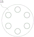
FIG. 2 is a schematic top view of the rotating plate of the present invention;
FIG. 3 is an enlarged schematic view of part A of the present invention;
FIG. 4 is an enlarged schematic view of part B of the present invention;
fig. 5 is an enlarged schematic view of the part C of the present invention.
In the figure: the device comprises a top plate 1, a connecting rod 2, a gear 3, a first motor 4, a rack 5, a movable block 6, a supporting plate 7, a hydraulic rod 8, an injection molding groove 9, an injection mold 10, a limiting rod 11, a workbench 12, supporting legs 13, a second motor 14, a rotating plate 15, a limiting plate 16, a return spring 17, a fixing plate 18, a threaded rod 19, a double-shaft motor 20, a mounting block 21, a sliding block 22, a fixing block 23, a limiting groove 24 and a sliding groove 25.
Detailed Description
The technical solutions in the embodiments of the present invention will be described clearly and completely with reference to the accompanying drawings in the embodiments of the present invention, and it is obvious that the described embodiments are only some embodiments of the present invention, not all embodiments. Based on the embodiments in the present invention, all other embodiments obtained by a person skilled in the art without creative work belong to the protection scope of the present invention.
Referring to fig. 1-5, the present invention provides a technical solution: a multi-station injection mold convenient for material taking comprises a workbench 12, support legs 13 are welded and installed at the bottom of the workbench 12, the number of the support legs 13 is four, the support legs are arranged at the bottom of the workbench 12 in a rectangular array mode, a support plate 7 is welded and installed at the top of the workbench 12, the number of the support plates 7 is two, the support plates 7 are arranged in parallel and correspondingly, a top plate is welded and installed at the top of the support plate 7, connecting rods 2 are welded and installed on corresponding surfaces of the support plates 7, racks 5 are welded and installed at the top and the bottom of the connecting rods 2, movable blocks 6 are sleeved and installed on the connecting rods 2, the number of the movable blocks 6 is two, the movable blocks 6 are of an internal hollow structure, gears 3 are rotatably installed on the inner walls of the front side and the rear side of the movable blocks 6, the gears 3 are two groups of gears 3 sequentially located at the top and the bottom of, an output shaft of a first motor 4 transversely penetrates through the movable blocks 6 through a coupler and is welded and connected with a rotating shaft of the gear 3, hydraulic rods 8 are welded and installed at the bottoms of the two groups of movable blocks 6, an installation block 21 is welded and installed at the telescopic end of one group of the hydraulic rods 8, a sliding groove 25 is formed in the bottom of the installation block 21, a sliding block 22 is arranged in the sliding groove 25, the number of the sliding blocks 22 is two, the sliding blocks 22 are slidably connected with the sliding groove 25, threaded rods 19 are rotatably installed on the inner walls of the two sides of the sliding groove 25, the sliding blocks 22 are sequentially sleeved on the threaded rods 19 and are in threaded connection with the threaded rods 19, a double-shaft motor 20 is welded and installed at the position, located in the middle of the sliding groove 25, of the inner walls of the front side and the rear side of the sliding groove 25, the output shaft of the double-shaft motor 20 is welded, the other group of telescopic ends of the hydraulic rods 8 are welded with an injection mold 10, the top of the workbench 12 is positioned in the center of the top of the workbench 12 and is rotatably provided with a rotating plate 15, the bottom of the rotating plate 15 is provided with a limiting groove 24, the top of the limiting groove 24 in the shape of a circular ring is positioned under the limiting groove 24 and is welded with a limiting rod 11, the top of the limiting rod 11 is rotatably provided with a roller which is positioned in the limiting groove 24, the bottom of the device is provided with the limiting groove 24, the rotating plate 15 can always keep the stability of the device when rotating operation is carried out through the matching use of the limiting rod 11, thereby improving the yield quality of the device to a certain degree and greatly improving the use safety of the device at the same time, the top of the rotating plate 15 is provided with injection molding grooves 9, the number of the injection molding grooves 9 is six groups and is matched with the injection mold 10, limiting plates 16 are welded and mounted on two sides of the bottom of the injection molding groove 9, the bottom of each limiting plate 16 longitudinally penetrates through the bottom of the injection molding groove 9, fixing plates 18 are welded and mounted on outer walls of two sides of each injection molding groove 9, the bottom of each limiting plate 16 longitudinally penetrates through the fixing plate 18 and is in sliding connection with the fixing plate 18, a return spring 17 is welded and mounted at the top of each fixing plate 18, the bottom of each limiting plate 16 is sleeved in the return spring 17, a second motor 14 is welded and mounted at the bottom of the workbench 12, an output shaft of the second motor 14 longitudinally penetrates through the workbench 12 through a coupler and is in welding connection with a rotating shaft of the rotating plate 15, the device enables uninterrupted operation of the device by arranging the injection molding grooves 9 on one rotating plate 15, the device is different from single-to-single injection molding, the production efficiency of the device is improved to a certain degree, and meanwhile, the device, thereby saving the time of the user to a certain extent and improving the practicability of the injection mold.
The working principle is as follows: when the device starts to work, the first motor 4 is driven to drive the movable block 6 to move transversely to the position right above the injection molding groove 9, one group of the driving hydraulic rods 8 is used for injection molding of the injection molding groove 9, meanwhile, the second motor 14 is driven to drive the rotating plate to rotate, so that the injection molding groove 9 after injection molding is moved to the position right below the other group of the hydraulic rods 8, the other group of the hydraulic rods 8 are driven, meanwhile, the double-shaft motor 20 is driven to drive the fixed block 23 to move transversely to support a finished product, and the work is finished.
Although embodiments of the present invention have been shown and described, it will be appreciated by those skilled in the art that changes, modifications, substitutions and alterations can be made in these embodiments without departing from the principles and spirit of the invention, the scope of which is defined in the appended claims and their equivalents.
Claims (6)
1. The utility model provides a multistation injection mold convenient to get material, includes workstation (12), its characterized in that: supporting legs (13) are installed in the bottom welding of workstation (12), the quantity of supporting legs (13) is four groups and is the rectangular array and arranges and install in the bottom of workstation (12), backup pad (7) are installed in the top welding of workstation (12), the quantity of backup pad (7) is two sets of and is the parallel corresponding setting, roof (1) is installed in the top welding of backup pad (7), connecting rod (2) are installed in the face of correspondence welding of backup pad (7), the top and the equal welded mounting in bottom of connecting rod (2) have rack (5), the cover is established on connecting rod (2) and is installed movable block (6), the quantity of movable block (6) is two sets of and movable block (6) is inside hollow structure, the front and back side inner wall of movable block (6) rotates and installs gear (3), first motor (4) are installed in the preceding lateral wall welding of movable block (6), the output shaft of first motor (4) transversely runs through movable block (6) and with the pivot of gear (3) through the shaft The welding connection device comprises two groups of movable blocks (6), hydraulic rods (8) are welded and installed at the bottoms of the two groups of movable blocks, installation blocks (21) are welded and installed at the telescopic ends of one group of the hydraulic rods (8), sliding grooves (25) are formed in the bottoms of the installation blocks (21), sliding blocks (22) are arranged in the sliding grooves (25), the quantity of the sliding blocks (22) is two groups, the sliding blocks (22) are slidably connected with the sliding grooves (25), threaded rods (19) are installed on the inner walls of the two sides of the sliding grooves (25) in a rotating mode, double-shaft motors (20) are welded and installed at the centers of the sliding grooves (25) on the inner walls of the front side and the rear side of the sliding grooves (25), output shafts of the double-shaft motors (20) are welded and connected with the free ends of the threaded rods (19) through couplers, fixed blocks (23) are welded and installed on the outer side walls of the, the top of the workbench (12) is positioned in the center of the top of the workbench (12) and is rotatably provided with a rotating plate (15), the bottom of the rotating plate (15) is provided with a limiting groove (24), the top of the limiting groove (24) in the shape of a circular ring is positioned under the limiting groove (24) and is welded with a limiting rod (11), the top of the rotating plate (15) is provided with an injection molding groove (9), both sides of the bottom of the injection molding groove (9) are respectively welded with a limiting plate (16), the bottom of the limiting plate (16) longitudinally penetrates through the bottom of the injection molding groove (9), outer walls of both sides of the injection molding groove (9) are welded with a fixing plate (18), the bottom of the limiting plate (16) longitudinally penetrates through the fixing plate (18) and is arranged in sliding connection with the fixing plate (18), the top of the fixing plate (18) is welded with a reset spring (17), and the bottom of the limiting, the bottom of the workbench (12) is welded with a second motor (14), and an output shaft of the second motor (14) longitudinally penetrates through the workbench (12) through a coupler and is welded with a rotating shaft of the rotating plate (15).
2. The multi-station injection mold convenient for material taking as claimed in claim 1, is characterized in that: the number of the gears (3) is two groups, which are sequentially arranged at the top and the bottom of the connecting rod (2) and meshed with the racks (5) on the connecting rod (2).
3. The multi-station injection mold convenient for material taking as claimed in claim 1, is characterized in that: the sliding blocks (22) are sequentially sleeved on the threaded rods (19) and are in threaded connection with the threaded rods (19).
4. The multi-station injection mold convenient for material taking as claimed in claim 1, is characterized in that: and a rubber pad is welded on the outer side wall of the fixed block (23).
5. The multi-station injection mold convenient for material taking as claimed in claim 1, is characterized in that: the top of the limiting rod (11) is rotatably provided with a roller, and the roller is positioned in the limiting groove (24).
6. The multi-station injection mold convenient for material taking as claimed in claim 1, is characterized in that: the number of the injection molding grooves (9) is six and the six groups of injection molding grooves are matched with the injection mold (10).
Priority Applications (1)
| Application Number | Priority Date | Filing Date | Title |
|---|---|---|---|
| CN202020454438.8U CN212219061U (en) | 2020-04-01 | 2020-04-01 | Multi-station injection mold convenient for material taking |
Applications Claiming Priority (1)
| Application Number | Priority Date | Filing Date | Title |
|---|---|---|---|
| CN202020454438.8U CN212219061U (en) | 2020-04-01 | 2020-04-01 | Multi-station injection mold convenient for material taking |
Publications (1)
| Publication Number | Publication Date |
|---|---|
| CN212219061U true CN212219061U (en) | 2020-12-25 |
Family
ID=73905744
Family Applications (1)
| Application Number | Title | Priority Date | Filing Date |
|---|---|---|---|
| CN202020454438.8U Active CN212219061U (en) | 2020-04-01 | 2020-04-01 | Multi-station injection mold convenient for material taking |
Country Status (1)
| Country | Link |
|---|---|
| CN (1) | CN212219061U (en) |
-
2020
- 2020-04-01 CN CN202020454438.8U patent/CN212219061U/en active Active
Similar Documents
| Publication | Publication Date | Title |
|---|---|---|
| CN205185198U (en) | Electric double -colored injection moulding of accurate oil of intelligence machine | |
| CN210705559U (en) | Plastic mold convenient for replacing lower mold | |
| CN214872329U (en) | PLA cutter processing is with once high-efficient injection mold of many boards | |
| CN212219061U (en) | Multi-station injection mold convenient for material taking | |
| CN213593524U (en) | Multi-station automatic rotating mold for injection molding of plastic covers of electronic products | |
| CN212736712U (en) | Cleaning device for injection mold | |
| CN214266295U (en) | Injection mold for injection molding machine | |
| CN212684599U (en) | Stable and demolding device convenient for demolding multiple groups of molds simultaneously for injection molding machine | |
| CN210759071U (en) | Mould distance adjusting device for injection molding production | |
| CN210026050U (en) | Positioning mechanism of injection molding machine for truck instrument panel | |
| CN210999786U (en) | Injection mold location structure with drying function | |
| CN213260825U (en) | Plastic injection mold of high-efficient production | |
| CN217704268U (en) | Mould is used in TV backlight processing of convenient unloading | |
| CN220162745U (en) | Brick mould permeates water | |
| CN216127616U (en) | Device convenient to injection molding machine retooling | |
| CN216267233U (en) | Multicolor vertical injection molding machine | |
| CN214239183U (en) | Injection molding device special for processing plastic parts of kitchen and bathroom electrical appliances | |
| CN214725995U (en) | Injection mold with injection molding head convenient to disassemble and assemble | |
| CN213962116U (en) | Automatic processing sole stamping equipment with limit structure | |
| CN217196753U (en) | Demoulding device of electric core support injection mold | |
| CN220903975U (en) | Buried bolt type injection molding die | |
| CN220261875U (en) | Precise die injection molding and separating equipment | |
| CN217862463U (en) | Double-color injection mold with movable rear mold | |
| CN112248336B (en) | Intelligent injection molding device for plastic processing and use method | |
| CN221022212U (en) | Injection mold with cooling structure |
Legal Events
| Date | Code | Title | Description |
|---|---|---|---|
| GR01 | Patent grant | ||
| GR01 | Patent grant |