CN212684599U - Stable and demolding device convenient for demolding multiple groups of molds simultaneously for injection molding machine - Google Patents
Stable and demolding device convenient for demolding multiple groups of molds simultaneously for injection molding machine Download PDFInfo
- Publication number
- CN212684599U CN212684599U CN202020766643.8U CN202020766643U CN212684599U CN 212684599 U CN212684599 U CN 212684599U CN 202020766643 U CN202020766643 U CN 202020766643U CN 212684599 U CN212684599 U CN 212684599U
- Authority
- CN
- China
- Prior art keywords
- pipe
- injection molding
- groove
- molding machine
- self
- Prior art date
- Legal status (The legal status is an assumption and is not a legal conclusion. Google has not performed a legal analysis and makes no representation as to the accuracy of the status listed.)
- Expired - Fee Related
Links
Images


Landscapes
- Moulds For Moulding Plastics Or The Like (AREA)
Abstract
The utility model discloses an injection molding machine is with stable and be convenient for shedder to multiunit mould drawing of patterns simultaneously, which comprises a bod, the inside of organism is provided with the equipment groove, and installs the cylinder in the equipment groove, the upper end of cylinder is connected in the lower surface of backup pad, and the last fixed surface of backup pad is connected with the fried dough twist pole, the inside of fried dough twist pipe is stretched into to the upper end of fried dough twist pole, and fried dough twist bearing of tubes connects in the inside of mounting groove, the outside key-type connection of fried dough twist pipe has the transmission pinion, and the meshing of transmission pinion connects between the transmission gear wheel, transmission gear wheel key-type connection is in the outside of supporting the swivelling duct. This injection molding machine can make the mould drawing of patterns more stable with being convenient for to the shedder of multiunit mould drawing of patterns simultaneously, has avoided in the past because the cylinder trouble causes fashioned component to be damaged when the drawing of patterns to can make multiunit mould drawing of patterns simultaneously, help improving the efficiency of injection molding machine drawing of patterns.
Description
Technical Field
The utility model relates to an injection mold technical field specifically is an injection molding machine is with stable and be convenient for to the shedder of multiunit mould drawing of patterns simultaneously.
Background
The injection molding machine is a device for manufacturing thermoplastic plastics or thermosetting plastics into plastic products with various shapes, and when the injection molding machine is used for demolding, a movable mold stripper plate is driven to move mainly through a cylinder, so that a molded component is pushed out of a mold;
but the shedder of current injection molding machine is not stable enough, and can not carry out the while drawing of patterns to multiunit mould simultaneously, this is because current injection molding machine shedder is when using, when driving movable mould stripper plate through the cylinder and remove, often because certain cylinder trouble for movable mould stripper plate can not stable removal, and then makes fashioned component atress inhomogeneous, so that fashioned component is damaged, and because can't guarantee that the cylinder is synchronous to be worked, so also be convenient for guarantee movable mould stripper plate stable removal.
Disclosure of Invention
An object of the utility model is to provide an injection molding machine is with stable and be convenient for to the shedder of multiunit mould drawing of patterns simultaneously to the shedder who proposes current injection molding machine in solving above-mentioned background is not stable enough, and can not carry out the problem of drawing of patterns simultaneously to the multiunit mould simultaneously.
In order to achieve the above object, the utility model provides a following technical scheme: the utility model provides a stable shedder who just is convenient for drawing of patterns simultaneously to multiunit mould for injection molding machine, includes the organism, the inside of organism is provided with the equipment groove, and the equipment inslot installs the cylinder, the upper end of cylinder is connected in the lower surface of backup pad, and the last fixed surface of backup pad is connected with the fried dough twist pole, the upper end of fried dough twist pole stretches into the inside of fried dough twist pipe, and fried dough twist pipe bearing connects in the inside of mounting groove, the outside key-type connection of fried dough twist pipe has the drive pinion, and the meshing of drive pinion connects between the drive gear wheel, the drive gear wheel key-type connection is in the outside of supporting the rotatory pipe, and the lower extreme bearing of supporting the rotatory pipe connects in the interior bottom of mounting groove, the upper end fixedly connected with connecting rod of supporting the rotatory pipe, and the connecting rod stretches into and sets up in the spread groove, the spread groove sets up in the lower extreme of, the inner side of the self-resetting rotary pipe is communicated with the upper surface of the machine body, a second guide groove and a first guide groove are respectively formed in the inner side surfaces of the self-resetting rotary pipe and the supporting rotary pipe, a movable mold core and a positioning pipe are fixedly connected to the bottom of an installation groove in the inner side of the supporting rotary pipe, the upper end of the positioning pipe is nested in the outer side of the lower end of the positioning rod, the upper end of the positioning rod is fixedly connected to the lower surface of a movable mold stripper plate, the movable mold stripper plate is nested in the outer side of the movable mold core, a guide block is fixedly connected to the outer side of the movable mold stripper plate, and the.
Preferably, the cylinder and the twist rod are arranged at intervals, and the outer side of the twist rod is connected with the inner side of the twist pipe in a twist-shaped threaded connection mode.
Preferably, the self-resetting rotary pipe and the supporting rotary pipe have equal inner diameters, and the axes of the self-resetting rotary pipe and the supporting rotary pipe are collinear.
Preferably, the number of the supporting rotary pipes is twice that of the twisted pipes, and each 2 supporting rotary pipes and 1 twisted pipe form a group.
Preferably, the first guide grooves and the second guide grooves are arranged in parallel, and the first guide grooves and the second guide grooves are symmetrically arranged.
Preferably, the connecting groove is arc-shaped, and the arc center of the connecting groove is positioned in the axial direction of the self-resetting rotating pipe.
Compared with the prior art, the beneficial effects of the utility model are that: this injection molding machine can make the mould drawing of patterns more stable with being convenient for to the shedder of multiunit mould drawing of patterns simultaneously, has avoided in the past because the cylinder trouble causes fashioned component to be damaged when the drawing of patterns to can make multiunit mould drawing of patterns simultaneously, help improving the efficiency of injection molding machine drawing of patterns:
1. the twist pipe can rotate by moving the twist rod relative to the twist pipe, so that the transmission pinion can easily drive the transmission big gear to rotate, the support rotating pipe rotates, the first guide groove rotates, and the guide block drives the movable mould stripper plate to move until the demoulding of the formed component is finished;
2. through connecting rod and the spread groove of connecting between from the rotatory pipe that restores to the throne and the support rotatory pipe, can make support the rotatory pipe and rotate certain angle and make first guiding groove and second guiding groove collineation when, drive from the rotatory pipe synchronous rotation that restores to the throne to make the guide block can slide to the second guiding groove from first guiding groove, help drawing of patterns the shaping component completely, and when the device is not used, first guiding groove and second guiding groove stagger, avoided the movable mould to take off the flitch and pulled out the device.
Drawings
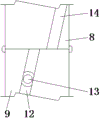
FIG. 1 is a schematic view of the present invention in a partial cross-sectional view;
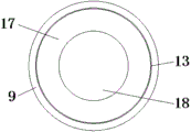
FIG. 2 is a schematic cross-sectional view of the self-resetting rotary pipe and the supporting rotary pipe of the present invention;
fig. 3 is a schematic view of the self-resetting rotary tube of the present invention;
FIG. 4 is a schematic top view of the supporting rotary tube of the present invention;
fig. 5 is the connecting structure schematic diagram of the moving die stripper plate of the present invention.
In the figure: 1. a body; 2. an equipment groove; 3. a cylinder; 4. a support plate; 5. a twisted rod; 6. a twist pipe; 7. mounting grooves; 8. a self-resetting rotating tube; 9. supporting the rotating tube; 10. a driving gearwheel; 11. a drive pinion; 12. a first guide groove; 13. a guide block; 14. a second guide groove; 15. connecting grooves; 16. a connecting rod; 17. a moving die stripper plate; 18. a movable mold core; 19. a positioning tube; 20. and (5) positioning the rod.
Detailed Description
The technical solutions in the embodiments of the present invention will be described clearly and completely with reference to the accompanying drawings in the embodiments of the present invention, and it is obvious that the described embodiments are only some embodiments of the present invention, not all embodiments. Based on the embodiments in the present invention, all other embodiments obtained by a person skilled in the art without creative work belong to the protection scope of the present invention.
Referring to fig. 1-5, the present invention provides a technical solution: a stable demoulding device convenient for demoulding a plurality of groups of moulds simultaneously for an injection moulding machine comprises a machine body 1, an equipment groove 2, a cylinder 3, a support plate 4, a twist rod 5, a twist pipe 6, a mounting groove 7, a self-reset rotary pipe 8, a support rotary pipe 9, a transmission big gear 10, a transmission small gear 11, a first guide groove 12, a guide block 13, a second guide groove 14, a connecting groove 15, a connecting rod 16, a movable mould stripper 17, a movable mould core 18, a positioning pipe 19 and a positioning rod 20, wherein the machine body 1 is internally provided with the equipment groove 2, the cylinder 3 is arranged in the equipment groove 2, the upper end of the cylinder 3 is connected with the lower surface of the support plate 4, the upper surface of the support plate 4 is fixedly connected with the twist rod 5, the upper end of the twist rod 5 extends into the twist pipe 6, the twist pipe 6 is connected with the mounting groove 7 in a bearing manner, the outer side key of the twist pipe, the transmission pinion 11 is engaged and connected between the transmission gear wheels 10, the transmission gear wheels 10 are connected with the outer side of the supporting rotary pipe 9 in a key mode, the lower end of the supporting rotary pipe 9 is connected with the inner bottom of the installation groove 7 in a bearing mode, the upper end of the supporting rotary pipe 9 is fixedly connected with a connecting rod 16, the connecting rod 16 extends into the connecting groove 15, the connecting groove 15 is arranged at the lower end of the self-resetting rotary pipe 8, the outer side of the upper end of the self-resetting rotary pipe 8 is connected with the inner top of the installation groove 7 in a bearing mode, the inner side of the self-resetting rotary pipe 8 penetrates through the upper surface of the machine body 1, the inner side surfaces of the self-resetting rotary pipe 8 and the supporting rotary pipe 9 are respectively provided with a second guide groove 14 and a first guide groove 12, the bottom of the installation groove 7 at the inner side of the supporting rotary pipe, the upper end of the positioning rod 20 is fixedly connected to the lower surface of the movable mold stripper plate 17, the movable mold stripper plate 17 is nested and arranged on the outer side of the movable mold core 18, the guide block 13 is fixedly connected to the outer side of the movable mold stripper plate 17, and the guide block 13 is slidably connected in the first guide groove 12.
The cylinder 3 and the twist rod 5 are arranged at intervals, the outer side of the twist rod 5 is connected with the inner side of the twist tube 6 in a twisted thread connection mode, and the twist rod 5 can be conveniently and stably moved up and down through the cylinder 3.
The inner diameters of self-resetting rotary pipe 8 and supporting rotary pipe 9 are equal, and the axes of the two are collinear, which can facilitate the guide block 13 to move from the first guide groove 12 on the supporting rotary pipe 9 to the second guide groove 14 on the self-resetting rotary pipe 8.
The number of the supporting rotary pipes 9 is twice that of the twist pipes 6, and every 2 supporting rotary pipes 9 and 1 twist pipe 6 form a group, so that the single twist pipe 6 can rotate conveniently, and 2 moulds can be synchronously demoulded.
The connecting groove 15 is arc-shaped, and the arc center of the connecting groove is positioned in the axial direction of the self-resetting rotating pipe 8, so that the self-resetting rotating pipe 8 can be driven to synchronously rotate after the supporting rotating pipe 9 rotates to a certain angle.
The working principle is as follows: install on the injection molding machine this injection molding machine with stable and be convenient for shedder to the simultaneous drawing of patterns of multiunit mould to switch on the device's power, the following mode of operation of rethread uses:
according to fig. 1-5, after the component is formed, the cylinder 3 is started, and when the cylinder is started, the support plate 4 is driven to stably move upwards, so that the twist rod 5 stably moves upwards;
when the twist rod 5 moves upwards, the twist tube 6 can rotate, and the supporting rotary tube 9 has larger torque force when rotating through the meshed connection of the transmission small gear 11 and the transmission big gear 10;
when the supporting rotary pipe 9 rotates, the movable mould stripper plate 17 is limited by the positioning pipe 19 and the positioning rod 20, so that the movable mould stripper plate 17 moves upwards by the guide block 13 sliding in the first guide groove 12;
when the supporting rotary pipe 9 rotates, the connecting rod 16 thereon rotates in the connecting groove 15, when the connecting rod 16 rotates to the end of the connecting groove 15, the supporting rotary pipe 9 drives the self-resetting rotary pipe 8 to synchronously rotate, and at the moment, the first guide groove 12 and the second guide groove 14 are collinear;
thereafter, the supporting rotary pipe 9 and the self-resetting rotary pipe 8 rotate synchronously, so that the guide block 13 slides from the first guide groove 12 into the second guide groove 14, and the movable stripper plate 17 can push the molded component out of the mold completely, which is not described in detail in this specification and is well known to those skilled in the art.
It is to be understood that the terms "central," "longitudinal," "lateral," "front," "rear," "left," "right," "vertical," "horizontal," "top," "bottom," "inner," "outer," and the like are used in the orientations and positional relationships indicated in the drawings for the purpose of convenience and simplicity of description, and are not intended to indicate or imply that the referenced devices or elements must be in a particular orientation, constructed and operated in a particular orientation, and are not to be construed as limiting the scope of the present invention.
Although embodiments of the present invention have been shown and described, it will be appreciated by those skilled in the art that changes, modifications, substitutions and alterations can be made in these embodiments without departing from the principles and spirit of the invention, the scope of which is defined in the appended claims and their equivalents.
Claims (6)
1. The utility model provides an injection molding machine is with stable and be convenient for to shedder of multiunit mould simultaneous demoulding, includes organism (1), its characterized in that: the inside of organism (1) is provided with equipment groove (2), and installs cylinder (3) in equipment groove (2), the upper end of cylinder (3) is connected in the lower surface of backup pad (4), and the last fixed surface of backup pad (4) is connected with fried dough twist pole (5), the inside of fried dough twist pipe (6) is stretched into to the upper end of fried dough twist pole (5), and fried dough twist pipe (6) bearing connection in the inside of mounting groove (7), the outside key-type connection of fried dough twist pipe (6) has drive pinion (11), and drive pinion (11) meshing connection between drive gear wheel (10), drive gear wheel (10) key-type connection is in the outside of supporting swivel pipe (9), and the lower extreme bearing of supporting swivel pipe (9) connects in the interior bottom of mounting groove (7), the upper end fixedly connected with connecting rod (16) of supporting swivel pipe (9), and the connecting rod (16) is inserted into the connecting groove (15) to be arranged, the connecting groove (15) is arranged at the lower end of the self-resetting rotating pipe (8), the outer side of the upper end of the self-resetting rotating pipe (8) is in bearing connection with the inner top of the mounting groove (7), the inner side of the self-resetting rotating pipe (8) is communicated to the upper surface of the machine body (1), the inner side surfaces of the self-resetting rotating pipe (8) and the supporting rotating pipe (9) are respectively provided with a second guide groove (14) and a first guide groove (12), the bottom of the mounting groove (7) at the inner side of the supporting rotating pipe (9) is fixedly connected with a movable mold core (18) and a positioning pipe (19), the upper end of the positioning pipe (19) is nested and arranged at the outer side of the lower end of the positioning rod (20), the upper end of the positioning rod (20) is fixedly connected to the lower surface of the movable mold stripper plate (, the outer side of the movable mold stripper plate (17) is fixedly connected with a guide block (13), and the guide block (13) is connected in the first guide groove (12) in a sliding manner.
2. The injection molding machine of claim 1, wherein the demolding device is configured to demold the plurality of sets of molds simultaneously, and comprises: the cylinder (3) and the twist rod (5) are arranged at intervals, and the outer side of the twist rod (5) is connected with the inner side of the twist pipe (6) in a twist-shaped threaded connection mode.
3. The injection molding machine of claim 1, wherein the demolding device is configured to demold the plurality of sets of molds simultaneously, and comprises: the inner diameters of the self-reset rotary pipe (8) and the supporting rotary pipe (9) are equal, and the axes of the self-reset rotary pipe and the supporting rotary pipe are collinear.
4. The injection molding machine of claim 1, wherein the demolding device is configured to demold the plurality of sets of molds simultaneously, and comprises: the number of the supporting rotary pipes (9) is twice that of the twisted pipes (6), and each 2 supporting rotary pipes (9) and 1 twisted pipe (6) form a group.
5. The injection molding machine of claim 1, wherein the demolding device is configured to demold the plurality of sets of molds simultaneously, and comprises: the first guide grooves (12) and the second guide grooves (14) are arranged in parallel, and the first guide grooves (12) and the second guide grooves (14) are symmetrically arranged.
6. The injection molding machine of claim 1, wherein the demolding device is configured to demold the plurality of sets of molds simultaneously, and comprises: the connecting groove (15) is arc-shaped, and the arc center of the connecting groove is positioned in the axial direction of the self-resetting rotating pipe (8).
Priority Applications (1)
| Application Number | Priority Date | Filing Date | Title |
|---|---|---|---|
| CN202020766643.8U CN212684599U (en) | 2020-05-11 | 2020-05-11 | Stable and demolding device convenient for demolding multiple groups of molds simultaneously for injection molding machine |
Applications Claiming Priority (1)
| Application Number | Priority Date | Filing Date | Title |
|---|---|---|---|
| CN202020766643.8U CN212684599U (en) | 2020-05-11 | 2020-05-11 | Stable and demolding device convenient for demolding multiple groups of molds simultaneously for injection molding machine |
Publications (1)
| Publication Number | Publication Date |
|---|---|
| CN212684599U true CN212684599U (en) | 2021-03-12 |
Family
ID=74887842
Family Applications (1)
| Application Number | Title | Priority Date | Filing Date |
|---|---|---|---|
| CN202020766643.8U Expired - Fee Related CN212684599U (en) | 2020-05-11 | 2020-05-11 | Stable and demolding device convenient for demolding multiple groups of molds simultaneously for injection molding machine |
Country Status (1)
| Country | Link |
|---|---|
| CN (1) | CN212684599U (en) |
Cited By (1)
| Publication number | Priority date | Publication date | Assignee | Title |
|---|---|---|---|---|
| CN115709551A (en) * | 2023-01-05 | 2023-02-24 | 杭州中好蔚莱电子有限公司 | Automobile injection molding part forming device and forming process thereof |
-
2020
- 2020-05-11 CN CN202020766643.8U patent/CN212684599U/en not_active Expired - Fee Related
Cited By (1)
| Publication number | Priority date | Publication date | Assignee | Title |
|---|---|---|---|---|
| CN115709551A (en) * | 2023-01-05 | 2023-02-24 | 杭州中好蔚莱电子有限公司 | Automobile injection molding part forming device and forming process thereof |
Similar Documents
| Publication | Publication Date | Title |
|---|---|---|
| CN212684599U (en) | Stable and demolding device convenient for demolding multiple groups of molds simultaneously for injection molding machine | |
| CN116674137B (en) | Demolding device and method for rubber processing | |
| CN209794323U (en) | Precise cavity mold of photovoltaic current sensing device | |
| CN115123757B (en) | Full-automatic aluminium system hose apparatus for producing | |
| CN215619645U (en) | Mould is used in car handle production with quick drawing of patterns function | |
| CN211542019U (en) | Glove demolding auxiliary device for production of epidemic prevention gloves | |
| CN211566801U (en) | Full-automatic hydraulic core-pulling pipe bending equipment | |
| CN211968194U (en) | Thin wall injection molding is with pressing from both sides tight positioner | |
| CN218139835U (en) | Plastic suction forming die | |
| CN213613668U (en) | Stamping die for automobile metal parts | |
| CN214324075U (en) | Tire processing is with mould of convenient quick drawing of patterns | |
| CN218660619U (en) | Convenient fixed mould | |
| CN220763514U (en) | Mould opening and closing device in bottle blowing machine | |
| CN216179737U (en) | Simple grinding wheel pressing die structure | |
| CN219522892U (en) | Novel die structure for three-time slider screw thread withdrawal | |
| CN218425052U (en) | Spinning machine for part machining | |
| CN221537924U (en) | Car body production die convenient for discharging | |
| CN213563817U (en) | Plastic mould ejection mechanism | |
| CN219520288U (en) | Mold processing die convenient to demolding | |
| CN211683321U (en) | Plastic mould shedder | |
| CN220883144U (en) | Injection mold fixing device for injection molding machine | |
| CN217196753U (en) | Demoulding device of electric core support injection mold | |
| CN213972260U (en) | Special mould for large-scale high-precision complex-structure plastic wine gun | |
| CN221391836U (en) | Rubber tire vulcanizer convenient to dismantle tire | |
| CN116811158B (en) | Processing device for co-mixing plastic products |
Legal Events
| Date | Code | Title | Description |
|---|---|---|---|
| GR01 | Patent grant | ||
| GR01 | Patent grant | ||
| CF01 | Termination of patent right due to non-payment of annual fee | ||
| CF01 | Termination of patent right due to non-payment of annual fee |
Granted publication date: 20210312 Termination date: 20210511 |