CN212192526U - Machining part flattening device - Google Patents
Machining part flattening device Download PDFInfo
- Publication number
- CN212192526U CN212192526U CN202020689856.5U CN202020689856U CN212192526U CN 212192526 U CN212192526 U CN 212192526U CN 202020689856 U CN202020689856 U CN 202020689856U CN 212192526 U CN212192526 U CN 212192526U
- Authority
- CN
- China
- Prior art keywords
- dust collecting
- mounting
- top end
- machined part
- dust
- Prior art date
- Legal status (The legal status is an assumption and is not a legal conclusion. Google has not performed a legal analysis and makes no representation as to the accuracy of the status listed.)
- Active
Links
Images


Abstract
The utility model discloses a machined part levels processingequipment, including outer framework, processing head, base and dust collecting tank, the base top is provided with outer framework, and the inside base top of outer framework is provided with the symmetry and is provided with the supporting seat, the outside cover on supporting seat top is equipped with the erection column, and transversely is provided with the mounting groove between the erection column top, mounting groove top symmetry is provided with splint, the inside top symmetry of outer framework is provided with the pneumatic cylinder, and the pneumatic cylinder output all is provided with the telescopic link, transversely be provided with the diaphragm between the telescopic link bottom, and the welding of installation pole bottom has the processing head, the diaphragm bottom of installation pole both sides all is provided with the dust collecting tank, and one side of dust collecting tank lower extreme all is provided with the. The utility model discloses because the structural design of half wheel and rack drives the piston and slides in the dust collecting tank is inside for the dust inhales the dust collecting tank, has improved energy utilization when having avoided operational environment to pollute.
Description
Technical Field
The utility model relates to a machined part technical field specifically is machined part levels processingequipment.
Background
The mechanical processing mainly comprises two types of manual processing and numerical control processing. Manual machining refers to a method in which a machinist manually operates mechanical equipment such as a milling machine, a lathe, a drilling machine, and a sawing machine to machine various materials. In the machining process, leveling machining is necessary to meet machining requirements, and the existing machining part leveling machining device can generate a large amount of dust, easily causes environmental pollution and affects working efficiency.
SUMMERY OF THE UTILITY MODEL
To above problem, the utility model provides a machining part levels processingequipment because the structural design of half wheel and rack drives the piston and slides in the dust collecting tank is inside for the dust inhales the dust collecting tank, has improved energy utilization when having avoided operational environment to pollute, can effectively solve the problem in the background art.
In order to achieve the above object, the utility model provides a following technical scheme: the machining part flattening device comprises an outer frame body, a machining head, a base and a dust collecting groove, wherein the outer frame body is arranged at the top end of the base, and the top end of the base inside the outer frame body is symmetrically provided with supporting seats, the outer side of the top end of each supporting seat is sleeved with an installation column, and a mounting groove is transversely arranged between the top ends of the mounting columns, the top ends of the mounting groove are symmetrically provided with clamping plates, the top end inside the outer frame body is symmetrically provided with hydraulic cylinders, and the output ends of the hydraulic cylinders are provided with telescopic rods, a transverse plate is transversely arranged between the bottom ends of the telescopic rods, and a driving motor is arranged at the central position of the top end of the transverse plate, an output end of the driving motor is provided with a mounting rod penetrating through the transverse plate, and the bottom end of the mounting rod is welded with a machining head, the bottom ends of the transverse plates at the two sides of the mounting rod are provided with dust collecting grooves, and one side of the lower end of each dust collecting groove is provided with a dust hood.
Preferably, the top end of the supporting seat extends into the mounting column and is provided with a first spring, and the supporting seat is connected with the mounting column in a sliding manner.
Preferably, the inner side of the outer frame body is symmetrically provided with slide bars, and the side walls of the slide bars are in sliding connection with the transverse plate.
Preferably, pistons are arranged at the top ends of the inner parts of the dust collecting grooves, racks are transversely and symmetrically arranged between the pistons, and a half gear matched with the racks is arranged on the outer side of the mounting rod.
Preferably, a pulling plate is arranged at the bottom end of the dust collecting groove and is in sliding connection with the side wall of the dust collecting groove.
Preferably, the inside symmetry of suction hood is provided with the dog, and one side between the dog is provided with the bobble, the bobble opposite side passes through second spring and suction hood lateral wall welding.
Preferably, the inside symmetry of mounting groove is provided with the screw rod, and the inside symmetry of mounting groove in the screw rod outside is provided with the rod cover, the bottom of splint extends to inside and with the welding of rod cover top of mounting groove.
Compared with the prior art, the beneficial effects of the utility model are that: this machining part levels processingequipment is rational in infrastructure, has following advantage:
1. due to the structural design of the half gear and the rack, when the half gear rotates, the rack can be driven to move left and right, so that the piston is driven to slide in the dust collecting groove, when the piston slides towards the inner side of the dust collecting groove, thrust is formed, the small ball is tightly attached to the stop block, the dust hood channel is closed, when the piston slides towards the outer side of the dust collecting groove, suction is formed, the small ball breaks away from the stop block and stretches the second spring, dust is sucked into the dust collecting groove, and the energy utilization rate is improved while the working environment is prevented from being polluted.
2. Through the first spring that mounting groove below set up, polish on the one hand and can produce vibrations, move slightly and make first spring take place deformation on the supporting seat through the erection column to can slow down the influence that vibrations brought, on the other hand when the thickness of polishing reduces, because the elastic action of first spring can make the machined part shift up voluntarily, avoided frictional force to reduce and the surface that leads to polish inhomogeneous, thereby improved the quality and the efficiency of polishing.
Drawings
Fig. 1 is a schematic front view of a cross-sectional structure of the present invention;
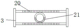
fig. 2 is a schematic top view of the rack and pinion mechanism of the present invention;
fig. 3 is an enlarged schematic view of a portion a in fig. 1 according to the present invention.
In the figure: 1. a drive motor; 2. an outer frame body; 3. a piston; 4. a machining head; 5. a slide bar; 6. a screw; 7. a first spring; 8. a supporting seat; 9. a base; 10. mounting a column; 11. a rod sleeve; 12. mounting grooves; 13. a splint; 14. a drawing plate; 15. a dust collecting groove; 16. mounting a rod; 17. a transverse plate; 18. a telescopic rod; 19. a hydraulic cylinder; 20. a rack; 21. a half gear; 22. a dust hood; 23. a pellet; 24. a stopper; 25. a second spring.
Detailed Description
The technical solutions in the embodiments of the present invention will be described clearly and completely with reference to the accompanying drawings in the embodiments of the present invention, and it is obvious that the described embodiments are only some embodiments of the present invention, not all embodiments. Based on the embodiments in the present invention, all other embodiments obtained by a person skilled in the art without creative work belong to the protection scope of the present invention.
Referring to fig. 1-3, the present invention provides an embodiment: the machining part flattening device comprises an outer frame body 2, a machining head 4, a base 9 and a dust collecting groove 15, wherein the outer frame body 2 is arranged at the top end of the base 9;
the inner side of the outer frame body 2 is symmetrically provided with slide bars 5, and the side walls of the slide bars 5 are connected with a transverse plate 17 in a sliding way;
the hydraulic cylinder 19 is driven to enable the transverse plate 17 to slide on the sliding rod 5, so that the stability of the movement of the machining head 4 can be enhanced;
supporting seats 8 are symmetrically arranged at the top end of a base 9 in the outer frame body 2;
the top end of the supporting seat 8 extends into the mounting column 10 and is provided with a first spring 7, and the supporting seat 8 is connected with the mounting column 10 in a sliding manner;
when the polishing generates vibration, the mounting column 10 slightly moves on the supporting seat 8 and the first spring 7 deforms, so that the influence caused by the vibration can be reduced, and on the other hand, when the polishing thickness is reduced, a workpiece automatically moves upwards due to the elastic action of the first spring 7, so that the uneven surface polishing caused by the reduction of friction force is avoided;
the outer side of the top end of the supporting seat 8 is sleeved with mounting columns 10, and mounting grooves 12 are transversely arranged between the top ends of the mounting columns 10;
the screw rods 6 are symmetrically arranged in the mounting groove 12, the rod sleeves 11 are symmetrically arranged in the mounting groove 12 on the outer side of the screw rods 6, and the bottom end of the clamping plate 13 extends into the mounting groove 12 and is welded with the top end of the rod sleeve 11;
due to the threaded fit between the screw rod 6 and the rod sleeve 11, when the screw rod 6 rotates, the clamping plate 13 can be driven to move, so that the workpiece is clamped and fixed;
the top end of the mounting groove 12 is symmetrically provided with clamping plates 13, the top end inside the outer frame body 2 is symmetrically provided with hydraulic cylinders 19, the output ends of the hydraulic cylinders 19 are respectively provided with a telescopic rod 18, a transverse plate 17 is transversely arranged between the bottom ends of the telescopic rods 18, a driving motor 1 is arranged at the central position of the top end of the transverse plate 17, the model of the driving motor 1 is Y90S-6, the output end of the driving motor 1 is provided with a mounting rod 16 penetrating through the transverse plate 17, the bottom end of the mounting rod 16 is welded with a processing head 4, and the bottom ends of the transverse plates 17 at the;
a drawing plate 14 is arranged at the bottom end of the dust collecting groove 15, and the drawing plate 14 is connected with the side wall of the dust collecting groove 15 in a sliding manner;
the dust in the dust collecting groove 15 can be removed by moving the drawing plate 14;
due to the structural design of the half gear 21 and the rack 20, when the half gear 21 rotates, the rack 20 is driven to move back and forth left and right, so that the piston 3 is driven to slide in the dust collecting groove 15;
and one side of the lower end of the dust collecting groove 15 is provided with a dust hood 22;
the inner part of the dust hood 22 is symmetrically provided with stop blocks 24, one side between the stop blocks 24 is provided with a small ball 23, and the other side of the small ball 23 is welded with the side wall of the dust hood 22 through a second spring 25;
when the piston 3 slides towards the inner side of the dust collection groove 15, thrust is formed, the small ball 23 is tightly attached to the stop 24, the passage of the dust collection cover 22 is closed, when the piston 3 slides towards the outer side of the dust collection groove 15, suction is formed, the small ball 23 is separated from the stop 24 and stretches the second spring 25, and therefore dust is sucked into the dust collection groove 15.
The working principle is as follows: when the device is used, firstly, a workpiece to be machined is placed at the top end of the mounting groove 12, the screw 6 is manually rotated, due to the fact that the screw 6 is in threaded fit with the rod sleeve 11, when the screw 6 rotates, the clamping plate 13 can be driven to move so as to clamp and fix the workpiece, then the hydraulic cylinder 19 is driven, the transverse plate 17 can slide on the sliding rod 5, the moving stability of the machining head 4 can be enhanced, when the machining head 4 is in contact with the surface layer of the workpiece to be machined, the driving motor 1 starts to drive to work, and the driving motor 1 can drive the machining head 4 to polish the workpiece through the mounting rod 16 so as to enable the workpiece to;
meanwhile, due to the structural design of the half gear 21 and the rack 20, when the half gear 21 rotates, the rack 20 is driven to move back and forth left and right, so that the piston 3 is driven to slide in the dust collecting groove 15, when the piston 3 slides towards the inner side of the dust collecting groove 15, thrust is formed, the small ball 23 is tightly attached to the stop block 24, the passage of the dust hood 22 is closed, when the piston 3 slides towards the outer side of the dust collecting groove 15, suction is formed, and at the moment, the small ball 23 is separated from the stop block 24 and stretches the second spring 25, so that dust is sucked into the dust collecting groove 15;
when polishing and producing vibrations, move slightly and make first spring 7 take place deformation on supporting seat 8 through erection column 10 to can slow down the influence that vibrations brought, on the other hand when the thickness of polishing reduces, because the elastic force of first spring 7 acts on, can make the machined part shift up voluntarily, avoided frictional force to reduce and the surface that leads to polish inhomogeneous.
Although embodiments of the present invention have been shown and described, it will be appreciated by those skilled in the art that changes, modifications, substitutions and alterations can be made in these embodiments without departing from the principles and spirit of the invention, the scope of which is defined in the appended claims and their equivalents.
Claims (7)
1. Machining spare levels processingequipment, including outer frame (2), processing head (4), base (9) and dust collection groove (15), its characterized in that: the device is characterized in that an outer frame body (2) is arranged at the top end of the base (9), supporting seats (8) are symmetrically arranged at the top end of the base (9) inside the outer frame body (2), mounting columns (10) are sleeved outside the top end of the supporting seats (8), mounting grooves (12) are transversely arranged between the top ends of the mounting columns (10), clamping plates (13) are symmetrically arranged at the top ends of the mounting grooves (12), hydraulic cylinders (19) are symmetrically arranged at the top end inside the outer frame body (2), telescopic rods (18) are arranged at the output ends of the hydraulic cylinders (19), transverse plates (17) are transversely arranged between the bottom ends of the telescopic rods (18), a driving motor (1) is arranged at the central position of the top end of the transverse plates (17), a mounting rod (16) penetrating through the transverse plates (17) is arranged at the output end of the driving motor, the bottom ends of the transverse plates (17) at the two sides of the mounting rod (16) are respectively provided with a dust collecting groove (15), and one side of the lower end of the dust collecting groove (15) is respectively provided with a dust hood (22).
2. The machined part flattening machining apparatus according to claim 1, characterized in that: the top end of the supporting seat (8) extends to the inside of the mounting column (10) and is provided with a first spring (7), and the supporting seat (8) is connected with the mounting column (10) in a sliding mode.
3. The machined part flattening machining apparatus according to claim 1, characterized in that: the inner side of the outer frame body (2) is symmetrically provided with slide bars (5), and the side walls of the slide bars (5) are slidably connected with the transverse plate (17).
4. The machined part flattening machining apparatus according to claim 1, characterized in that: pistons (3) are arranged at the top ends of the inner parts of the dust collecting grooves (15), racks (20) are transversely and symmetrically arranged between the pistons (3), and half gears (21) matched with the racks (20) are arranged on the outer sides of the mounting rods (16).
5. The machined part flattening machining apparatus according to claim 1, characterized in that: the bottom end of the dust collecting groove (15) is provided with a drawing plate (14), and the drawing plate (14) is in sliding connection with the side wall of the dust collecting groove (15).
6. The machined part flattening machining apparatus according to claim 1, characterized in that: the inside symmetry of suction hood (22) is provided with dog (24), and one side between dog (24) is provided with bobble (23), bobble (23) opposite side passes through second spring (25) and suction hood (22) lateral wall welding.
7. The machined part flattening machining apparatus according to claim 1, characterized in that: the inside symmetry of mounting groove (12) is provided with screw rod (6), and the inside symmetry of mounting groove (12) in the screw rod (6) outside is provided with rod cover (11), the bottom of splint (13) extends to inside and the welding of rod cover (11) top of mounting groove (12).
Priority Applications (1)
| Application Number | Priority Date | Filing Date | Title |
|---|---|---|---|
| CN202020689856.5U CN212192526U (en) | 2020-04-29 | 2020-04-29 | Machining part flattening device |
Applications Claiming Priority (1)
| Application Number | Priority Date | Filing Date | Title |
|---|---|---|---|
| CN202020689856.5U CN212192526U (en) | 2020-04-29 | 2020-04-29 | Machining part flattening device |
Publications (1)
| Publication Number | Publication Date |
|---|---|
| CN212192526U true CN212192526U (en) | 2020-12-22 |
Family
ID=73831465
Family Applications (1)
| Application Number | Title | Priority Date | Filing Date |
|---|---|---|---|
| CN202020689856.5U Active CN212192526U (en) | 2020-04-29 | 2020-04-29 | Machining part flattening device |
Country Status (1)
| Country | Link |
|---|---|
| CN (1) | CN212192526U (en) |
Cited By (1)
| Publication number | Priority date | Publication date | Assignee | Title |
|---|---|---|---|---|
| CN112847104A (en) * | 2021-01-07 | 2021-05-28 | 林金辉 | Surface polishing device for metal plate |
-
2020
- 2020-04-29 CN CN202020689856.5U patent/CN212192526U/en active Active
Cited By (1)
| Publication number | Priority date | Publication date | Assignee | Title |
|---|---|---|---|---|
| CN112847104A (en) * | 2021-01-07 | 2021-05-28 | 林金辉 | Surface polishing device for metal plate |
Similar Documents
| Publication | Publication Date | Title |
|---|---|---|
| CN102189405B (en) | Numerical control milling and drilling machine | |
| CN103894833B (en) | A kind of digital control hole drilling groover | |
| CN210307112U (en) | Steel plate beveling machine | |
| CN212636090U (en) | Cutting mechanism for processing aerated concrete building blocks | |
| CN212192526U (en) | Machining part flattening device | |
| CN202097553U (en) | Numerical-control milling and drilling machine | |
| CN203804557U (en) | Numerical control drilling grooving machine | |
| CN219504142U (en) | Numerical control machine tool frame | |
| CN201565784U (en) | Magnetic seat automatic milling device | |
| CN109277608B (en) | Double-milling-head machining device | |
| CN111687660A (en) | Swash plate type axial plunger pump machining device | |
| CN215280933U (en) | Adjustable center frame | |
| CN211439031U (en) | Drilling die for machine tool body | |
| CN109434520B (en) | Clamp for machining cylinder body | |
| CN208289320U (en) | A kind of car cage top frame supporting device for welding | |
| CN111644642A (en) | Combined control vertical array tool changing system | |
| CN219881823U (en) | Clamping tool for machining stainless steel tube | |
| CN209936343U (en) | Gantry milling and boring machine frame with high bearing performance | |
| CN200970651Y (en) | Numerical control locomotive side frame combined miller | |
| CN201399687Y (en) | Device for adjusting center rest of heavy-duty horizontal lathe | |
| CN2776646Y (en) | Automatic gang drill | |
| CN218946477U (en) | Water conservancy pipeline cutting mechanism | |
| CN114131071B (en) | Double-end boring machine | |
| CN219053579U (en) | Double-drive range-extending conveying table for gantry boring and milling machining center | |
| CN219234584U (en) | Positioning fixture of multi-spindle drilling machine |
Legal Events
| Date | Code | Title | Description |
|---|---|---|---|
| GR01 | Patent grant | ||
| GR01 | Patent grant | ||
| TR01 | Transfer of patent right | ||
| TR01 | Transfer of patent right |
Effective date of registration: 20230529 Address after: 266000 Dongyi Road, daxueyuan, Huangdao District, Qingdao City, Shandong Province Patentee after: Qingdao Dingfa Technology Service Co.,Ltd. Address before: No.1883, Taifa Road, Huangdao District, Qingdao City, Shandong Province Patentee before: QINGDAO SHENGMAOYUAN PRECISION MACHINERY MOULD MANUFACTURING Co.,Ltd. |