CN212169796U - Gear hobbing machine coolant liquid and iron fillings recovery unit - Google Patents
Gear hobbing machine coolant liquid and iron fillings recovery unit Download PDFInfo
- Publication number
- CN212169796U CN212169796U CN202020364489.1U CN202020364489U CN212169796U CN 212169796 U CN212169796 U CN 212169796U CN 202020364489 U CN202020364489 U CN 202020364489U CN 212169796 U CN212169796 U CN 212169796U
- Authority
- CN
- China
- Prior art keywords
- cooling liquid
- recovery box
- box
- recovery
- scrap iron
- Prior art date
- Legal status (The legal status is an assumption and is not a legal conclusion. Google has not performed a legal analysis and makes no representation as to the accuracy of the status listed.)
- Expired - Fee Related
Links
Images
Landscapes
- Grinding-Machine Dressing And Accessory Apparatuses (AREA)
Abstract
The utility model discloses a gear hobbing machine cooling liquid and scrap iron recovery device, which comprises a machine tool, a workbench, a positioning device, a fixing clamp, a gear piece to be processed, a hob head, a cooling liquid box, an infusion pump, a nozzle, a cooling liquid recovery box, a recovery box cover, a filter disc, a baffle plate and a scrap receiving box, wherein the cooling liquid and the scrap iron fall into the filter disc through the recovery box cover, the falling cooling liquid and the scrap iron are filtered and separated through the filter screen, after the scrap iron is filtered by the filter disc, the scrap iron rises along the inner wall of the filter disc under the action of centrifugal force, the scrap iron is thrown out through an inner side through hole of the recovery box cover, the scrap iron is blocked by the baffle plate and falls into the scrap receiving box, the cooling liquid flows back into the cooling liquid box through the cooling liquid recovery box, the scrap iron and the cooling liquid are all received, and are respectively recovered after separation, the utilization efficiency of the cooling liquid is improved, the economic benefit is improved.
Description
Technical Field
The utility model relates to a gear machining technical field specifically is a gear hobbing machine coolant liquid and iron fillings recovery unit.
Background
The numerical control gear hobbing machine is suitable for batch, small batch and single piece production and processing of cylindrical gears and worm gears, 6 teeth with the length less than 300 and short spline shafts with the length more than 6 teeth can be continuously subjected to indexing hobbing by a spline hobbing cutter for the drum gears with certain parameters, and a chain wheel can be subjected to hobbing by the sprocket hobbing cutter. The process of processing the cylindrical gear can adopt the reverse milling and the forward milling hobbing, the full tooth width is processed by adopting an axial feeding method, cooling liquid must be used for cooling in the cutting process, the cooling liquid is a grease substance and is high in price, a circulating use method is generally adopted, but a large amount of scrap irons can be carried in the process of recycling the cooling liquid, the separation is not thorough, the cooling pipe is blocked, the production process is interrupted, the production efficiency is reduced, the existing scrap irons and the cooling liquid are separated by adopting a standing and precipitating mode, the scrap irons are difficult to clean because the cooling liquid leads to adhesion and a bottom plate, and the working environment is influenced.
SUMMERY OF THE UTILITY MODEL
An object of the utility model is to provide a gear hobbing machine coolant liquid and iron fillings recovery unit to solve the problem that proposes among the above-mentioned background art.
In order to achieve the above object, the utility model provides a following technical scheme:
a cooling liquid and scrap iron recovery device of a gear hobbing machine comprises a machine tool, a workbench, a positioning device, a fixing clamp, gear pieces to be machined, a hobbing cutter frame, a cooling liquid box, an infusion pump, a nozzle, a cooling liquid recovery box, a recovery box cover, a filter disc, a baffle plate and a scrap receiving box, wherein the positioning device, the workbench and the hobbing cutter frame are arranged on the top surface of the machine tool;
a cooling liquid tank is arranged on the right side of the machine tool, the cooling liquid tank is a square box body filled with cooling liquid, an infusion pump is arranged at the top of the cooling liquid tank, an input pipeline of the infusion pump extends into the inner cavity of the cooling liquid tank from the top of the cooling liquid tank and is close to the bottom of the inner cavity, the output end of the infusion pump is fixedly connected with a nozzle on a hobbing cutter frame through a pipeline, the nozzle is arranged in a mode of aligning to the hobbing cutter, the cooling liquid can be sprayed onto the cutting part of the hobbing cutter, and the cutting temperature is reduced;
the top surface of the workbench is fixedly connected with a cooling liquid recovery box, the cooling liquid recovery box is of a hollow cylinder structure with an open top surface, a circular through hole is formed in the center of the bottom surface of the cooling liquid recovery box, a sleeve is fixedly connected in the through hole and is sleeved on a rotary seat at the top of the workbench, a recovery box cover is sleeved at the top of the cooling liquid recovery box and is a circular cover with an open bottom surface, a step is arranged at the bottom of the inner wall of the recovery box, the inner diameter of the step is the same as the outer diameter of the cooling liquid recovery box, the cooling liquid recovery box and the recovery box cover are fixed in an interference connection and matching mode, a circular through hole is formed in the center of the top surface of the recovery box cover, a circle of horn-shaped convex edge is arranged on the top surface of the recovery box;
the bottom of the outer wall of the fixing clamp is fixedly connected with a filter disc, the filter disc is of a circular disc-shaped structure with a circular through hole in the center, the central through hole is fixedly connected with a sleeve, the sleeve is fixedly connected to the outer wall of the fixing clamp, so that the fixing clamp can drive the filter disc to rotate when rotating, the circular through holes are uniformly arranged on the side wall of the filter disc in an array mode, a steel wire filter screen is padded on the inner wall of the filter disc, and falling cooling liquid and scrap iron can be filtered and separated;
the scrap collecting box is characterized in that a square through hole is formed in the side wall, close to the inner side, of the recycling box cover, a material baffle is fixedly connected to the inner side of the recycling box cover, the bottom surface of the material baffle is open, a scrap collecting box is placed on the bottom surface of the material baffle, the scrap collecting box is a square box body with an open top surface, scrap is filtered by a filter disc, and under the action of centrifugal force, the scrap rises along the inner wall of the filter disc, is thrown out through the through hole in the inner side of the recycling box cover, is blocked by the material baffle;
as a further aspect of the present invention: a liquid outlet is formed in the position, close to the bottom, of the front face of the cooling liquid recovery box and is connected with a liquid inlet of the cooling liquid box through a pipeline, and cooling liquid is directly recycled;
as a further aspect of the present invention: a liquid discharge port at the bottom of the cooling liquid recovery box is padded with a filter screen to prevent impurities in the cooling liquid from entering the cooling liquid box;
as a further aspect of the present invention: the cooling liquid recovery box, the recovery box cover and the filter disc are made of stainless steel materials, so that the cooling liquid can be prevented from being corroded, the cooling of the cooling liquid is accelerated, and the cooling liquid is convenient to recover;
as a further aspect of the present invention: a polytetrafluoroethylene filter screen is padded on the steel wire filter screen at the bottom of the inner cavity of the filter disc to prevent stains from being bonded, and the stains which cannot pass through and scrap iron are discharged together;
as a further aspect of the present invention: the outer wall of coolant liquid collection box is close to top department and is equipped with round silica gel sealing strip, improves the sealed effect of coolant liquid collection box and recovery case lid junction.
Compared with the prior art, the beneficial effects of the utility model are that: the top surface of retrieving the case lid is equipped with the chimb of round tubaeform along the edge of top surface through-hole, conveniently receive the coolant liquid that hobbing cutter department left and scrap iron down, coolant liquid and scrap iron fall into the filter tray through retrieving the case lid, coolant liquid and scrap iron filtering separation that will fall through the filter screen, after the filter tray filters down the scrap iron, scrap iron is under the effect of centrifugal force, scrap iron rises along the inner wall of filter tray, throw away through the inboard through-hole of retrieving the case lid, keep off by the striker plate, fall into in the scrap receiving case, coolant liquid flows back to in the coolant liquid case through the coolant liquid recovery case, accept scrap iron and coolant liquid are whole, and retrieve respectively after the separation, the utilization efficiency of coolant liquid has been improved, and can reduce the loss of coolant liquid, and economic benefits is improved.
Drawings
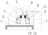
FIG. 1 is a schematic structural view of a cooling liquid and scrap iron recycling device of a gear hobbing machine.
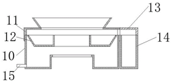
FIG. 2 is a schematic view of the structure of a recycling bin in the device for recycling coolant and iron filings of a gear hobbing machine.
In the figure: the device comprises a machine tool 1, a workbench 2, a positioning device 3, a fixing clamp 4, a gear piece to be processed 5, a hob head 6, a cooling liquid tank 7, an infusion pump 8, a nozzle 9, a cooling liquid recovery tank 10, a recovery tank cover 11, a filter disc 12, a material baffle 13, a scrap receiving tank 14 and a liquid discharge port 15.
Detailed Description
The technical solutions in the embodiments of the present invention will be described clearly and completely with reference to the accompanying drawings in the embodiments of the present invention, and it is obvious that the described embodiments are only some embodiments of the present invention, not all embodiments. Based on the embodiments in the present invention, all other embodiments obtained by a person skilled in the art without creative work belong to the protection scope of the present invention.
Referring to fig. 1-2, in an embodiment of the present invention, a device for recycling coolant and scrap iron of a gear hobbing machine includes a machine tool 1, a worktable 2, a positioning device 3, a fixing clamp 4, a gear piece 5 to be machined, a hob head 6, a coolant tank 7, a liquid delivery pump 8, a nozzle 9, a coolant recycling tank 10, a recycling tank cover 11, a filter disc 12, a material baffle 13 and a scrap receiving tank 14, the top surface of the machine tool 1 is provided with a positioning device 3, a workbench 2 and a hob head 6, the workbench 2 is of a hollow cuboid structure, a worm and worm gear transmission mechanism is arranged in the machine tool, the machine tool can drive a fixed clamp 4 at the top to rotate, a plurality of laminated gear pieces 5 to be processed are fixed on the fixed clamp 4 through a central rotating shaft, a pressing plate and nuts, a hob head 6 is arranged on the top surface of the machine tool 1, the hob head 6 is provided with a hobbing cutter and a cutter feeding mechanism, and can cut and process the gear piece 5 to be processed fixed on the fixed clamp 4;
a cooling liquid tank 7 is arranged on the right side of the machine tool 1, the cooling liquid tank 7 is a square box body filled with cooling liquid, an infusion pump 8 is arranged at the top of the cooling liquid tank, an input pipeline of the infusion pump 8 extends into the inner cavity of the cooling liquid tank 7 from the top of the cooling liquid tank 7 to be close to the bottom of the inner cavity, the output end of the infusion pump is fixedly connected with a nozzle 9 on a hob head 6 through a pipeline, the nozzle 9 is arranged in an alignment manner with the hob head, the cooling liquid can be sprayed onto the cutting part of the hob head, and the cutting temperature is reduced;
the top surface of the workbench 2 is fixedly connected with a cooling liquid recovery box 10, the cooling liquid recovery box 10 is of a hollow cylinder structure with an open top surface, a circular through hole is formed in the center of the bottom surface of the cooling liquid recovery box, a sleeve is fixedly connected in the through hole and sleeved on a rotary seat at the top of the workbench 2, a recovery box cover 11 is sleeved at the top of the cooling liquid recovery box 10, the recovery box cover 11 is a circular cover with an open bottom surface, a step is arranged at the bottom of the inner wall of the recovery box cover, the inner diameter of the step is the same as the outer diameter of the cooling liquid recovery box 10, the cooling liquid recovery box 10 and the recovery box cover 11 are fixed in an interference connection and matching mode, the circular through hole is formed in the center of the top surface of the recovery box cover 11, a circle of horn-shaped convex edge is arranged on the top surface of;
the bottom of the outer wall of the fixed clamp 4 is fixedly connected with a filter disc 12, the filter disc 12 is of a circular disc-shaped structure, the center of which is provided with a circular through hole, the central through hole is fixedly connected with a sleeve, the sleeve is fixedly connected with the outer wall of the fixed clamp 4, so that the fixed clamp 4 can drive the filter disc 12 to rotate when rotating, the circular through holes are uniformly arranged on the side wall of the filter disc 12 in an array manner, and a steel wire filter screen is padded on the inner wall of the filter disc, so that the falling cooling liquid and scrap iron can be;
the scrap collecting box is characterized in that a square through hole is formed in the side wall, close to the inner side, of the recycling box cover 11, a material baffle 13 is fixedly connected to the inner side of the recycling box cover, the bottom surface of the material baffle 13 is open, a scrap collecting box 14 is placed on the bottom surface of the material baffle 13, the scrap collecting box 14 is a square box body with an open top surface, and after scrap is filtered by the filter disc 12, the scrap rises along the inner wall of the filter disc 12 under the action of centrifugal force, is thrown out through the through hole in the inner side of the recycling box cover 11, is stopped by the material baffle 13 and;
a liquid outlet 15 is formed in the position, close to the bottom, of the front face of the cooling liquid recovery box 10, and the liquid outlet 15 is connected with a liquid inlet of the cooling liquid box 7 through a pipeline to directly recycle the cooling liquid;
a filter screen is padded at a liquid outlet 15 at the bottom of the cooling liquid recovery box 10 to prevent impurities in the cooling liquid from entering the cooling liquid box 7;
the cooling liquid recovery box 10, the recovery box cover 11 and the filter disc 12 are made of stainless steel materials, so that the cooling liquid can be prevented from being corroded, the cooling of the cooling liquid is accelerated, and the cooling liquid is convenient to recover;
a polytetrafluoroethylene filter screen is padded on a steel wire filter screen at the bottom of the inner cavity of the filter disc 12 to prevent stains from being bonded, and the stains which cannot pass through and scrap iron are discharged together;
the outer wall of coolant liquid recovery case 10 is close to top department and is equipped with round silica gel sealing strip, improves the sealed effect of coolant liquid recovery case 10 and recovery case lid 11 junction.
The utility model discloses a theory of operation is: the top surface of recovery case lid 11 is equipped with the chimb of round tubaeform along the edge of top surface through-hole, conveniently receive the coolant liquid that hobbing cutter department left and scrap iron down, coolant liquid and scrap iron fall into filter disc 12 through recovery case lid 11, coolant liquid and scrap iron filtering separation that will fall through the filter screen, filter disc 12 filters down behind the scrap iron, scrap iron is under the effect of centrifugal force, the scrap iron rises along the inner wall of filter disc 12, throw away through the inboard through-hole of recovering case lid 11, keep off by striker plate 13, fall into and connect in bits case 14, the coolant liquid flows back to in coolant liquid case 7 through coolant liquid recovery case 10.
Although the present invention has been described in detail with reference to the foregoing embodiments, it will be apparent to those skilled in the art that modifications may be made to the embodiments or portions thereof without departing from the spirit and scope of the invention.
Claims (6)
1. A cooling liquid and scrap iron recovery device of a gear hobbing machine comprises a machine tool, a workbench, a positioning device, a fixing clamp, gear pieces to be machined, a hobbing cutter frame, a cooling liquid box, an infusion pump, a nozzle, a cooling liquid recovery box, a recovery box cover, a filter disc, a baffle plate and a scrap receiving box, wherein the top surface of the machine tool is provided with the positioning device, the workbench and the hobbing cutter frame;
a cooling liquid tank is arranged on the right side of the machine tool, the cooling liquid tank is a square box body filled with cooling liquid, an infusion pump is arranged at the top of the cooling liquid tank, an input pipeline of the infusion pump extends into the inner cavity of the cooling liquid tank from the top of the cooling liquid tank to be close to the bottom of the inner cavity, the output end of the infusion pump is fixedly connected with a nozzle on a hob head through a pipeline, and the nozzle is aligned with the hob;
the top surface of the workbench is fixedly connected with a cooling liquid recovery box, the cooling liquid recovery box is of a hollow cylindrical structure with an open top surface, a circular through hole is formed in the center of the bottom surface of the cooling liquid recovery box, a sleeve is fixedly connected in the through hole and is sleeved on a rotary seat at the top of the workbench, a recovery box cover is sleeved at the top of the cooling liquid recovery box and is a circular cover with an open bottom surface, a step is arranged at the bottom of the inner wall of the recovery box, the inner diameter of the step is the same as the outer diameter of the cooling liquid recovery box, the cooling liquid recovery box and the recovery box cover are fixedly connected in an interference fit mode, a circular through hole is formed in the center of the top surface of the recovery box cover, and a circle;
the bottom of the outer wall of the fixing clamp is fixedly connected with a filter disc, the filter disc is of a circular disc-shaped structure, the center of the filter disc is provided with a circular through hole, the center through hole is fixedly connected with a sleeve, the sleeve is fixedly connected to the outer wall of the fixing clamp, so that the fixing clamp can drive the filter disc to rotate when rotating, the circular through holes are uniformly arrayed on the side wall of the filter disc, and a steel wire filter screen is padded on the inner wall of the filter disc;
the lateral wall of recovery case lid is close to the inboard and is equipped with square through-hole, its inboard fixedly connected with striker plate, the bottom surface opening of striker plate, its bottom surface have been placed and have been connect the bits case, connect the bits case to be top surface open-ended square box.
2. The gear hobbing machine cooling liquid and scrap iron recovery device according to claim 1, wherein a liquid outlet is formed in the front face of the cooling liquid recovery box near the bottom, and the liquid outlet is connected with a liquid inlet of the cooling liquid box through a pipeline.
3. The gear hobbing machine cooling liquid and scrap iron recovery device of claim 1, wherein a filter screen is padded at a drain outlet at the bottom of the cooling liquid recovery box.
4. The gear hobbing machine coolant and scrap iron recovery device of claim 1, wherein the coolant recovery tank, the recovery tank cover and the filter disc are stainless steel.
5. The gear hobbing machine coolant and scrap iron recovery unit of claim 1, wherein a polytetrafluoroethylene filter screen is padded on a steel wire filter screen at the bottom of the inner cavity of the filter disc.
6. The gear hobbing machine cooling liquid and scrap iron recovery device of claim 1, wherein a circle of silica gel sealing strip is arranged on the outer wall of the cooling liquid recovery box near the top.
Priority Applications (1)
| Application Number | Priority Date | Filing Date | Title |
|---|---|---|---|
| CN202020364489.1U CN212169796U (en) | 2020-03-20 | 2020-03-20 | Gear hobbing machine coolant liquid and iron fillings recovery unit |
Applications Claiming Priority (1)
| Application Number | Priority Date | Filing Date | Title |
|---|---|---|---|
| CN202020364489.1U CN212169796U (en) | 2020-03-20 | 2020-03-20 | Gear hobbing machine coolant liquid and iron fillings recovery unit |
Publications (1)
| Publication Number | Publication Date |
|---|---|
| CN212169796U true CN212169796U (en) | 2020-12-18 |
Family
ID=73771773
Family Applications (1)
| Application Number | Title | Priority Date | Filing Date |
|---|---|---|---|
| CN202020364489.1U Expired - Fee Related CN212169796U (en) | 2020-03-20 | 2020-03-20 | Gear hobbing machine coolant liquid and iron fillings recovery unit |
Country Status (1)
| Country | Link |
|---|---|
| CN (1) | CN212169796U (en) |
Cited By (2)
| Publication number | Priority date | Publication date | Assignee | Title |
|---|---|---|---|---|
| CN113262558A (en) * | 2021-02-05 | 2021-08-17 | 王雷 | Multi-unit cooling liquid recycling system for hardware fitting machining |
| CN114290243A (en) * | 2021-12-15 | 2022-04-08 | 郭传渠 | Part grinding device with cooling and cleaning functions |
-
2020
- 2020-03-20 CN CN202020364489.1U patent/CN212169796U/en not_active Expired - Fee Related
Cited By (3)
| Publication number | Priority date | Publication date | Assignee | Title |
|---|---|---|---|---|
| CN113262558A (en) * | 2021-02-05 | 2021-08-17 | 王雷 | Multi-unit cooling liquid recycling system for hardware fitting machining |
| CN114290243A (en) * | 2021-12-15 | 2022-04-08 | 郭传渠 | Part grinding device with cooling and cleaning functions |
| CN114290243B (en) * | 2021-12-15 | 2023-02-17 | 郭传渠 | Part grinding device with cooling and cleaning functions |
Similar Documents
| Publication | Publication Date | Title |
|---|---|---|
| CN212169796U (en) | Gear hobbing machine coolant liquid and iron fillings recovery unit | |
| CN110936220B (en) | Liquid and scrap separating device for machining center | |
| CN210817586U (en) | Drilling lathe convenient to retrieve coolant liquid | |
| CN210703865U (en) | Chip removal device of numerical control machine tool | |
| CN215232497U (en) | Novel filtering equipment for numerical control machine tool | |
| CN215036557U (en) | A sweeps recovery unit for milling process | |
| CN214322706U (en) | Arrange sword lathe convenient to chip removal supplies liquid | |
| CN212240239U (en) | Digit control machine tool with chip removal function | |
| CN219131663U (en) | Numerical control machine tool convenient for chip removal | |
| CN111347283A (en) | Automatic chip removal device of lathe | |
| CN216418452U (en) | Cooling liquid filtering device for machine tool machining | |
| CN216502734U (en) | Sawing machine with chip removal function | |
| CN214109058U (en) | Automatic cutting platform with garbage collection device | |
| CN215310759U (en) | Filter device for chip removal machine | |
| CN211193111U (en) | Milling machine | |
| CN212887068U (en) | Cast member processing sweeps collection device | |
| CN211639198U (en) | Automatic chip removal chip breaking module of chip winding of sharing chip removal machine | |
| CN210206759U (en) | Granulation mechanism of anti-sticking softener film granulator | |
| CN111975441A (en) | Automatic device of processing sweeps waste liquid with washing of numerical control processing | |
| CN209754700U (en) | Automatic chip removal device of milling machine for metal casting machining | |
| CN214392681U (en) | Mantle fiber machine with edulcoration device | |
| CN210255353U (en) | Chip collecting device of numerical control multi-spindle drilling machine | |
| CN209477948U (en) | A kind of building decoration engineering anti-splashing toothless saw | |
| CN215788543U (en) | Milling machine garbage collection device | |
| CN215145035U (en) | Semi-automatic bottom milling machine for door and window handle seat |
Legal Events
| Date | Code | Title | Description |
|---|---|---|---|
| GR01 | Patent grant | ||
| GR01 | Patent grant | ||
| CF01 | Termination of patent right due to non-payment of annual fee |
Granted publication date: 20201218 |
|
| CF01 | Termination of patent right due to non-payment of annual fee |