Automatic tooling switching device in vehicle body welding production line
Technical Field
The utility model relates to an automobile welding production technical field specifically is a frock automatic switching control equipment in automobile body welding production line.
Background
In the field of automatic production, the demand of collinearly producing like products with multiple specifications to save production equipment resources and fields is more and more obvious. The flexible growth promotion and intelligent line body layout scheme and the production process are continuously improved and perfected. The utility model discloses mainly weld the arbitrary occasion that dress automation line's actual demand evolves but its implementation mode can be borrowed in view of any needs special frock or the automatic quick replacement of material by white automobile body. In the automobile welding production process, a plurality of enterprises need to produce various different automobile models on a single production line, one production line needs different tool fixtures to clamp and finish welding production according to different automobile models, different sizes of workpieces are arranged at sub-assembly stations, loading requirements are different, and other various factors are different, the size and weight difference of the tool fixtures is large, and the flexibility of the tool fixture body is difficult to realize technically and financially in actual project application. Therefore, at present, to realize flexible multi-vehicle type mixed line production, multiple work fixtures must be switched. In addition, due to the fact that the production rhythm requirement of the automobile body welding production line and the market requirement for selecting any mixed line production mode or small-batch switching production mode are higher and higher, most of producers give up storing tools in a storage place far away from a production area, the traditional tool switching mode that turnover logistics equipment is transported and installed according to needs is utilized, the storage position of the tools is directly arranged on the edge of the production line, the production line is directly cut into when needed, the tools on the production line are replaced, and therefore switching time is saved, and precious production time is obtained.
SUMMERY OF THE UTILITY MODEL
An object of the utility model is to provide a frock automatic switching control equipment in automobile body welding production line to solve the problem that proposes in the above-mentioned background art.
In order to achieve the above object, the utility model provides a following technical scheme: the utility model provides a frock automatic switching control equipment in automobile body welding production line, includes that X is to moving the year dolly, X is to moving one side of carrying the dolly and installing the track body, and the both ends of the track body are provided with the accurate positioning mechanism in workstation ground, and X is provided with fixed storehouse position to the front end that moves the dolly, X is to moving and is installed XY to accurate positioning cylinder bolt mechanism on carrying the dolly, and XY is installed Z to accurate positioning floating mechanism to one side of accurate positioning cylinder bolt mechanism, X is to moving and is installed tow chain, servo motor, frock clamp guide wheel group, move and carry drive roller lead screw and move and carry driving motor on carrying the dolly respectively.
Preferably, a pneumoelectric energy quick-inserting mechanism is installed on one side of the servo motor, a tool clamp supporting wheel set is installed on one side of the tool clamp guiding wheel set, a tow hook guiding linear guide rail is installed on one side of the tool clamp supporting wheel set, a shear type structure is installed at one end of the tow hook guiding linear guide rail, a shear type structure driving node and a shear type structure terminal node are installed on the shear type structure, one end of a transfer driving motor is rotatably connected with a synchronous belt through a main shaft, and a transfer driving roller screw is connected with the transfer driving linear guide rail through a fixing piece.
Preferably, the XY direction fine positioning cylinder bolt mechanism is provided with a cylinder and an installation plate, two ends of the installation plate are connected with the connecting rod through hinge points, and the upper end of the connecting rod is provided with a hinge.
Preferably, the XY direction fine positioning cylinder bolt mechanism is internally provided with a track group, a positioning bolt and a limiting block.
Preferably, the Z-direction fine positioning floating mechanism is provided with a linear guide rail and a floating block, the surface of the linear guide rail is provided with a linear guide rail sliding block, and the upper end and the lower end of the floating block are respectively provided with an upper roller and a lower roller.
Preferably, the Z-direction fine positioning floating mechanism is provided with an X-direction fine positioning wheel set and a Y-direction fine positioning wheel set, the Z-direction fine positioning floating mechanism is provided with a height dimension, a tool clamp side slope supporting block is arranged inside the Z-direction fine positioning floating mechanism, and the lower end of the tool clamp side slope supporting block is provided with a slope supporting block.
Preferably, the track body is provided with a guide rail and a rack, and two sides of the X-direction transfer trolley are respectively provided with an X-direction transfer trolley supporting wheel, an X-direction transfer trolley guide wheel and an X-direction transfer trolley reverse pinch roller which are matched with each other to buckle the guide rail on the track body.
Preferably, the upper part of the fixed warehouse position is provided with a switchable fixture tool, the fixture tool is provided with a fixture bottom tow hook roller, and the X-direction trolley shear-structured tow hook is arranged during operation to tow the fixture bottom tow hook roller.
Compared with the prior art, the beneficial effects of the utility model are that:
(1) the warehouse position system which completes the warehouse position switching work in pairs and has a fixed switching stroke is redesigned, the functional mechanism dragged in the Y direction of the tool clamp is moved to the X-direction transverse trolley, and the using amount of the mechanism can be reduced and the cost can be reduced when the multi-warehouse position system is arranged in the same scheme;
(2) the X-direction transfer trolley drives a speed reducer and a gear through a servo motor, is meshed with a rack on a track body for transmission, and is guided by a roller and a guide plate structure to finish X-direction accurate transverse movement and positioning;
(3) the driving node and the terminal node of the shear type transverse moving structure are both designed with linear guide to ensure the direction controllability and the structure precision of the movement, the shear type transverse moving structure is driven by a motor through a synchronous belt mechanism to drive a ball screw to realize the accurate control of the stroke, the speed and the acceleration of the driving node, and the sudden acceleration impact and the accurate in-place movement during the warehouse cutting work are avoided;
(4) an XY-direction fine positioning bolt structure is installed on the X-direction transverse moving trolley, secondary accurate positioning of a process working position can be realized by matching with the design of a fine positioning wheel set on a fixture side and a ground rail side, the mechanism drives a connecting rod to prop open an upper positioning pin and a lower positioning pin which are accurately positioned by a linear guide rail through a cylinder, and simultaneous guide on the fixture and the ground two sides is realized, compared with a bush guide cylindrical pin scheme, a guide stroke can be ensured on a smaller space size, meanwhile, the three-point one-line self-locking principle of the connecting rod is utilized, the structure is ensured not to cause the positioning pins to accidentally retract, a good gas and power off protection effect is achieved, and in addition, compared with the original or other schemes, the using amount of the positioning;
(5) 4-8 unequal Z-direction floating positioning structures are arranged on the X-direction transverse moving trolley, when the trolley reaches the working position of the rail body, the distance between the ground rail positioning block and the supporting block at the lower side of the upper fixture is automatically expanded, and the 4-8 mechanisms are adjusted to be of uniform height size, so that the distance between the ground rail positioning block and the lower part of the tool fixture is uniform, and the Z-direction repeated positioning precision of the tool at the same position can be ensured;
(6) in the equipment, the fixed clamp storehouses are generally symmetrically arranged along two sides of the rail body, the towing hooks of the scissor mechanism are designed to be clamped into towing hook rollers of two tools simultaneously, so that the transverse moving structure can complete the work of warehousing the old clamp and warehousing the new clamp at the position of the storehouses, and the working beat of warehousing the old clamp and the new clamp is saved.
Drawings
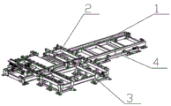
FIG. 1 is a general structural diagram of the present invention;
FIG. 2 is a structural diagram of the X-direction transfer trolley of the present invention;
FIG. 3 is a schematic view of the XY direction fine positioning cylinder plug mechanism of the present invention;
FIG. 4 is a view of the Z-direction fine positioning floating mechanism of the present invention;
fig. 5 is a Z-direction fine positioning explanatory diagram of the present invention;
fig. 6 is a cross-sectional structural view of the present invention.
In the figure: 1. a track body; 2. an X-direction transfer trolley; 3. fixing a warehouse location; 4. a ground fine positioning mechanism of a working position; 5. an XY-direction fine positioning cylinder bolt mechanism; 6. a Z-direction fine positioning floating mechanism; 7. a drag chain; 8. a gas-electric energy quick plug mechanism; 9. a servo motor; 10. a tool clamp guide wheel set; 11. a tool clamp supporting wheel set; 12. the towing hook is guided to the linear guide rail; 13. transferring and driving the roller screw; 14. the linear guide rail is driven by transferring; 15. a scissor-structured drive node; 16. a scissor structure; 17. a scissor-structured terminal node; 18. a synchronous belt; 19. a transfer drive motor; 20. a cylinder; 21. a hinge; 22. a connecting rod; 23. a hinge point; 24. mounting a plate; 25. positioning a bolt; 26. a limiting block; 27. a track set; 28. an upper roller; 29. a slider; 30. a linear guide slider; 31. a linear guide rail; 32. a lower roller; 33. a supporting block with a slope; 34. x-direction fine positioning wheel set; 35. a Y-direction fine positioning wheel set; 36. a height dimension; 37. the side of the tool clamp is provided with a slope supporting block; 38. a fixture tool; 39. a towing hook roller at the bottom of the clamp; 40. a scissor-structured tow hook; 41. x-direction load-transferring trolley supporting wheels; 42. a guide wheel of the X-direction transfer trolley; 43. the reverse pinch roller of the X-direction transfer trolley; 44. a guide rail; 45. a rack.
Detailed Description
The technical solutions in the embodiments of the present invention will be described clearly and completely with reference to the accompanying drawings in the embodiments of the present invention, and it is obvious that the described embodiments are only some embodiments of the present invention, not all embodiments.
Referring to fig. 1-6, the present invention provides an embodiment: the utility model provides a frock automatic switching control equipment in automobile body welding production line, including X to moving the dolly 2, X is to moving the dolly 2 one side and installing the track body 1, the both ends of track body 1 are provided with work position ground finish positioning mechanism 4, X is to moving the front end that the dolly 2 was moved and being provided with fixed storehouse position 3, X is to moving to install XY on the dolly 2 and to smart positioning cylinder bolt mechanism 5, XY is to smart positioning cylinder bolt mechanism 6 to one side of 5, X is to moving to install tow chain 7 on the dolly 2 respectively, servo motor 9, frock clamp direction wheelset 10, move and carry drive roller lead screw 13 and move and carry driving motor 19.
Further, a pneumoelectric energy quick-inserting mechanism 8 is installed on one side of a servo motor 9, a tool clamp supporting wheel set 11 is installed on one side of a tool clamp guiding wheel set 10, a towing hook guiding linear guide rail 12 is installed on one side of the tool clamp supporting wheel set 11, a shear type structure 16 is installed at one end of the towing hook guiding linear guide rail 12, a shear type structure driving node 15 and a shear type structure terminal node 17 are installed on the shear type structure 16, one end of a transfer driving motor 19 is rotatably connected with a synchronous belt 18 through a main shaft, and a transfer driving roller screw 13 is connected with a transfer driving linear guide rail 14 through a fixing piece.
Further, an air cylinder 20 and an installation plate 24 are installed on the XY direction fine positioning air cylinder plug pin mechanism 5, two ends of the installation plate 24 are connected with a connecting rod 22 through a hinge point 23, and a hinge 21 is installed at the upper end of the connecting rod 22.
Further, a track group 27, a positioning bolt 25 and a limiting block 26 are arranged inside the XY direction fine positioning cylinder bolt mechanism 5.
Further, a linear guide 31 and a slider 29 are mounted on the Z-direction fine positioning floating mechanism 6, a linear guide slider 30 is mounted on the surface of the linear guide 31, and an upper roller 28 and a lower roller 32 are mounted on the upper end and the lower end of the slider 29, respectively.
Further, an X-direction fine positioning wheel set 34 and a Y-direction fine positioning wheel set 35 are mounted on the Z-direction fine positioning floating mechanism 6, a height dimension 36 is arranged on the Z-direction fine positioning floating mechanism 6, a tool clamp side slope supporting block 37 is mounted inside the Z-direction fine positioning floating mechanism 6, and a slope supporting block 33 is arranged at the lower end of the tool clamp side slope supporting block 37.
Further, a guide rail 44 and a rack 45 are mounted on the track body 1, and an X-direction transfer trolley support wheel 41, an X-direction transfer trolley guide wheel 42 and an X-direction transfer trolley reverse pinch wheel 43 are respectively arranged on two sides of the X-direction transfer trolley 2, and are matched with each other to buckle the guide rail 44 on the track body 1.
Further, a switchable fixture tool 38 is arranged on the upper portion of the fixed warehouse 3, a fixture bottom tow hook roller 39 is arranged on the fixture tool 38, and a shear type structure tow hook 40 of the X-direction trolley is arranged during operation to tow the fixture bottom tow hook roller 39.
The working principle is as follows: when the device is used, a lever force arm amplification principle and a scissor-type structure are combined to design a Y-direction transverse moving structure, a servo motor 9 is utilized to drive a shifting driving roller screw 13 to push a scissor-type structure driving node 15 of a scissor-type structure 16, the node is made to move along the moving direction of the shifting driving roller screw 13, and simultaneously, along with the lever force arm amplification principle of the scissor-type structure, a scissor-type structure terminal node 17 is made to obtain a motion stroke which is amplified in multiple times in the guiding direction of a towing hook guiding linear guide rail 12, the transverse size of the driving structure can be reduced, and the longitudinal size of the whole set of mechanism can be restrained through the scissor-type structure, so that the whole structure can be placed into an X-direction shifting trolley 2 An XY-direction fine positioning cylinder bolt mechanism 5 and a Z-direction fine positioning floating mechanism 6. The XY-direction fine positioning cylinder bolt mechanism 5 provides accurate position restraint in XY directions of the X-direction transfer trolley 2, a clamp and the ground, the Z-direction fine positioning floating mechanism 6 provides accurate positioning of the distance between the clamp and the ground, the stretching of the cylinder 20 drives the hinge 21, the connecting rod 22 is pushed to rotate around the hinge point 23, the hinge point 23 is enabled to move along the action direction of the track group 27 while the connecting rod 22 rotates around the hinge point 23, the positioning bolt 25 is installed on the hinge point 23, and the track group 27 is connected to the installation plate 24 in a sliding block mode. Thus, the transverse movement of the piston of the cylinder 20 is converted into the longitudinal movement of the positioning bolt 25, the structure is implemented symmetrically up and down, when the device is used for fine positioning, the upper bolt is inserted into the corresponding positioning hole of the clamp, and the lower bolt is inserted into the corresponding X-direction fine positioning wheel set 34 and Y-direction fine positioning wheel set 35 of the ground fine positioning structure. The accurate restraint of the horizontal direction XY between the upper clamp and the lower ground positioning hole is realized through the processing precision of the two pins and the accurate guide of the track group 27, the limiting blocks 26 are positioned at the upper part and the lower part, the connecting rod 22 runs to a straight position which is just a structural self-locking point, and the pin can be ensured not to fall back during the non-production time or accident of line stop and power failure and gas failure, so that the danger of equipment failure or clamp slipping is prevented; the positioning bolt 25 is made into a square finish machining section, the top end of the periphery is provided with a guide angle, the positioning points of the clamp and the ground finish positioning points adopt the same 4-wheel set structure, every two groups of rollers control 1 horizontal direction and are mutually vertical in the horizontal plane, the distance between the outer edges of the wheels is matched with the machining surface of the positioning bolt 25, when the XY finish positioning is carried out, the positioning pin 25 enters an X-direction finish positioning wheel set 34 and a Y-direction finish positioning wheel set 35, the structure is easy to machine in place, the contact between the pins and the wheels is rolling friction, the abrasion can be effectively reduced, the service life of the pins and the wheel sets is prolonged, a Z-direction finish positioning floating mechanism 6 is arranged between the clamp and the ground finish positioning mechanism, a Z-direction space complementary floating structure is adopted, an upper roller 28 and a lower roller 32 are respectively arranged at two ends of a floating block 29, meanwhile, the floating block 29 is arranged on a linear guide, 4-8 structures are arranged on the X-direction transfer trolley 2 according to the weight and the size of the clamp corresponding to the actual project, and the distance between the upper roller 28 and the lower roller 32 of the structures is adjusted to be a uniform height dimension 36. Thus, when the trolley runs to the fine positioning station, the slope supporting block 33 on the ground fine positioning structure can support the structure and finally support the side slope supporting block 37 on the tool clamp on the clamp. When the positions of the slope supporting block 33, the height dimension 36 and the side slope supporting block 37 of the tool fixture of each Z-direction positioning point are adjusted uniformly, the Z-direction repeated precision of the fixture at the position can be ensured in the state, and the Z-direction fine positioning floating mechanism 6 realizes that the trolley advances in the X direction, the Z-direction positioning point can be implemented in a trolley frame, so that the fixture can be guided more fully and the equipment can run more reliably in the butt joint moving process of the moving warehouse; the movement of the X-direction transfer trolley 2 is driven by a speed reducer driven by a servo motor 9 and is meshed with a rack 45 on the track body 1 through a gear for transmission, an X-direction transfer trolley supporting wheel 41 is installed on the X-direction transfer trolley 2, an X-direction transfer trolley guide wheel 42 and an X-direction transfer trolley reverse pressing wheel 43 are attached to a guide rail 44, after the X-direction transfer trolley 2 is symmetrically installed on two sides, the X-direction transfer trolley 2 can move to an accurate stop position (such as a tooling moving position or a process working position of a warehouse area) along the track body 1, and the action principle of cutting and fixing the warehouse position 3 by the fixture tooling 38 is described as follows: the clamp tool 38 is placed on the fixed warehouse position 3, when the X-direction transfer trolley 2 moves to the warehouse cutting position, the scissor-structure towing hook 40 connected with the scissor-structure terminal node 17 stops at one end dragged by the X-direction transfer trolley 2 in advance, and enters the clamp bottom towing hook roller 39 to be clamped into the scissor-structure towing hook 40. When the clamp tool 38 is cut out, the shifting driving motor 19 drives the shifting driving roller screw 13 to rotate through the synchronous belt 18, so that the shear type structure driving node 15 of the shear type structure 16 is driven to move along the transverse moving direction, the parallel stroke is amplified to the shear type structure tow hook 40, the clamp tool 38 is driven to completely move to the transverse moving trolley, the cutting-out process is completed, in general use, the fixed warehouse positions 3 are symmetrically arranged along the track body 1, the shear type structure tow hook 40 is designed into double grooves and can be clamped into the tow hook rollers 39 at the bottoms of the clamps of the two tools at the same time, and therefore the transverse moving structure can complete the work of warehousing the old clamp and warehousing the work of ex-warehouse of the new clamp at the warehouse cutting position at the.
It is obvious to a person skilled in the art that the invention is not restricted to details of the above-described exemplary embodiments, but that it can be implemented in other specific forms without departing from the spirit or essential characteristics of the invention. The present embodiments are therefore to be considered in all respects as illustrative and not restrictive, the scope of the invention being indicated by the appended claims rather than by the foregoing description, and all changes which come within the meaning and range of equivalency of the claims are therefore intended to be embraced therein. Any reference sign in a claim should not be construed as limiting the claim concerned.