CN212159508U - Drying shrinkage testing device - Google Patents
Drying shrinkage testing device Download PDFInfo
- Publication number
- CN212159508U CN212159508U CN202020874929.8U CN202020874929U CN212159508U CN 212159508 U CN212159508 U CN 212159508U CN 202020874929 U CN202020874929 U CN 202020874929U CN 212159508 U CN212159508 U CN 212159508U
- Authority
- CN
- China
- Prior art keywords
- bottom plate
- test
- drying shrinkage
- sample
- measuring
- Prior art date
- Legal status (The legal status is an assumption and is not a legal conclusion. Google has not performed a legal analysis and makes no representation as to the accuracy of the status listed.)
- Active
Links
Images


Abstract
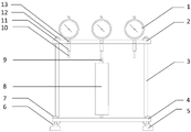
The utility model relates to a drying shrinkage testing arrangement, the main part includes the table frame and fixes the amesdial on the table frame, the table frame constitute by being connected with the bracing piece that table roof beam, bottom plate and both ends are connected respectively with table roof beam, bottom plate, the installation sets up a set of amesdial on the table roof beam, the bottom plate bottom is connected and is set up a set of horizontal support. The test device is provided with a test sample and placed in the constant temperature and humidity box, when test data needs to be obtained, the test sample can be directly observed through the glass door of the constant temperature and humidity box without taking out the test sample for measurement, and errors caused by changes between a measuring tool and a measuring point when multiple times of measurements are manually carried out are avoided; when having avoided taking out the measurement, because of the change of temperature, humidity produces the influence to the measuring result, has avoided the condition that the sample damaged and delayed the test progress in handling, and testing arrangement can provide a set of sample simultaneously and carry out parallel test, has improved efficiency of software testing.
Description
Technical Field
The utility model belongs to the technical field of building material inspection and detection technique and specifically relates to a drying shrinkage testing arrangement has been related to.
Background
The drying shrinkage of building materials, especially cement-based materials, is the main cause of the cracking of the current building frame and maintenance structure, and the national standards of autoclaved aerated concrete blocks (plates), load-bearing concrete porous bricks, concrete solid bricks, concrete hollow blocks and other building materials all stipulate the performance index requirements of the drying shrinkage value. The main materials of the enclosure structure, namely autoclaved aerated concrete products and sintered products, are generally based on the detection standards GB/T2542-, in the actual test process, the sample needs to be taken out of the constant temperature and humidity box, the absolute length of the sample is measured by an outside micrometer, the shrinkage rate is calculated by repeated measurement, because the requirement on the measurement precision is higher, the measurement positions of the outside micrometer and the sample can be changed in the process of manually carrying out multiple measurements, which brings larger errors to the test result, and after the sample is taken out from the constant temperature and humidity box, the change of the humidity and the temperature also influences the test result, and finally, ideal test data cannot be obtained, so that the detection accuracy and the detection efficiency are greatly reduced.
Disclosure of Invention
For solving the not enough of prior art, realize improving the purpose that detects precision and detection efficiency, the utility model discloses a following technical scheme:
the utility model provides a drying shrinkage testing arrangement, the main part includes the table frame and fixes the amesdial on the table frame, the table frame constitute by table roof beam, bottom plate and both ends are connected with the bracing piece that table roof beam, bottom plate are connected respectively, the installation sets up a set of amesdial on the table roof beam, the bottom plate bottom is connected and is set up a set of horizontal support. The test device is provided with a test sample and placed in the constant temperature and humidity box, when test data needs to be obtained, the test sample can be directly observed through the glass door of the constant temperature and humidity box without taking out the test sample for measurement, and errors caused by changes between a measuring tool and a measuring point when multiple times of measurements are manually carried out are avoided; when having avoided taking out the measurement, because of the change of temperature, humidity produces the influence to the measuring result, has avoided the condition that the sample damaged and delayed the test progress in handling, and testing arrangement can provide a set of sample simultaneously and carry out parallel test, has improved efficiency of software testing.
The dial gauge is characterized in that the gauge beam is provided with a mounting hole and a lateral locking screw hole corresponding to the mounting hole, and a measuring rod of the dial gauge is connected in the mounting hole in a penetrating manner and is fixedly connected with the mounting hole through the lateral locking screw hole by a locking screw. The distance between the dial indicator and the base can be adjusted by adjusting the fixed position of the measuring rod up and down so as to adapt to samples with different heights.
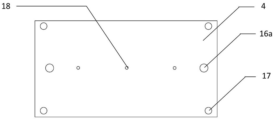
And the two ends of the supporting rod are provided with threaded tenon joints which are respectively in cross-connection fit with the surface beam connecting hole and the bottom plate connecting hole on the surface beam and the bottom plate and are fixedly connected through fastening nuts.
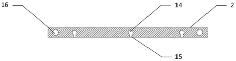
And a positioning notch is arranged on the bottom plate at a position corresponding to the measuring head of the dial indicator. The upper end and the lower end of the sample are embedded with the shrinkage heads, the positioning notch and the measuring head are respectively matched with the shrinkage heads at the upper end and the lower end, and the measuring head is provided with downward elasticity, so that the sample is vertically fixed and is measured in real time.
The horizontal support is provided with a screw which is connected with a support hole with threads on the bottom plate in a penetrating way and is fixed by a screw cap. Through the adjustment to the screw, can adjust the levelness of bottom plate to for the test provides horizontal test environment.
And an adjusting screw is arranged on the bottom plate at a position corresponding to a measuring head of the dial indicator, the adjusting screw is matched and connected with the adjusting screw hole, and the top end surface of the adjusting screw is provided with a positioning notch. The upper end and the lower end of the sample are embedded with the shrinkage heads, the alignment notch and the measuring head are respectively matched with the shrinkage heads at the upper end and the lower end, and the measuring head is provided with downward elastic force, so that the sample is vertically fixed, real-time measurement is carried out, and the distance between the alignment notch and the measuring head can be adjusted through the adjusting screw, so that the sample with different heights can be applied.
The measuring head of the dial indicator is a flat head. The contact of the surface and the point is formed at the matching part of the probe and the contraction head, and the contact is easier to correspond and more sufficient compared with the point when the probe is a sharp head.
The utility model discloses an advantage and beneficial effect lie in:
when having avoided measuring repeatedly, because of measuring the difference of position, measurement environment at every turn and causing the error, also avoided the damage that leads to because of the removal of sample in the testing process, and the condition of delaying the detection progress, and a plurality of samples can be surveyed simultaneously to this testing arrangement, have improved efficiency of software testing, whole testing arrangement can be dismantled simultaneously, simple structure, low cost, convenient operation, maintenance convenience, location are accurate.
Drawings
Fig. 1 is a schematic structural diagram of the present invention.
Fig. 2 is a top sectional view of the middle finger of the present invention.
Fig. 3 is a schematic structural diagram of the middle bottom plate of the present invention.
Fig. 4 is a cross-sectional view of the middle bottom plate and the sample according to the present invention.
Fig. 5 is a cross-sectional view of the middle plate, the sample and the adjusting screw according to the present invention.
In the figure: 1. the device comprises a dial gauge, 2, gauge beams, 3, support rods, 4, a bottom plate, 5, a horizontal support, 6, screws, 7, nuts, 8, a test sample, 9, a shrinkage head, 10, a measuring head, 11, a measuring rod, 12, a fastening nut, 13, locking screws, 14, mounting holes, 15, lateral locking screw holes, 16, gauge beam connecting holes, 16a, bottom plate connecting holes, 17, support holes, 18, positioning notches, 18a, alignment notches, 19, adjusting screws, 20 and adjusting screw holes.
Detailed Description
The present invention will be described in detail with reference to the accompanying drawings and specific embodiments. But does not limit the invention accordingly to the scope of the described embodiments.
As shown in fig. 1-4, a drying shrinkage testing device, the main body includes a gauge stand and a dial indicator 1 fixed on the gauge stand, the gauge stand is composed of a gauge beam 2, a bottom plate 4 and a support rod 3 with two ends respectively connected with the gauge beam 2 and the bottom plate 4, a set of three dial indicators 1 is installed on the gauge beam 2, and a set of four horizontal supports 5 is connected and arranged at the bottom of the bottom plate 4.
The dial gauge 2 is provided with a mounting hole 14 and a corresponding lateral locking screw hole 15, and the measuring rod 11 of the dial gauge 1 is penetrated in the mounting hole 14 and fixedly connected with the mounting hole by a locking screw 13 through the lateral locking screw hole 15. According to the test requirement, the specification of the sample 8 is usually 40x40x160 (mm) dry shrinkage strips, and when the samples 8 of other specifications need to be tested, the distance between the dial indicator 1 and the bottom plate 4 can be adjusted by adjusting the fixed position of the measuring rod 11 up and down so as to adapt to the samples 8 with different heights. According to the test requirements, generally three samples 8 are combined to be tested in parallel, so that the test efficiency is improved, and the number of the mounting holes 14, the lateral locking screw holes 15, the locking screws 13 and the corresponding dial indicators 1 on the dial indicator beam 2 can be expanded according to special requirements.
Threaded tenon joints are arranged at two ends of the support rod 3, are respectively in cross-connection fit with the surface beam connecting holes 16 and the bottom plate connecting holes 16a on the surface beam 2 and the bottom plate 4, and are fixedly connected through fastening nuts 12. Because the length of the measuring rod 11 is limited, the part fixed by the measuring rod 11 can be adjusted up and down only to finely adjust the testing device, when the height of the tested sample 8 is greatly changed compared with the conventional sample 8, the testing device can be adjusted greatly by the telescopic supporting rod 3 or the supporting rods 3 with different lengths can be replaced to adapt to samples 8 with different specifications.
The bottom plate 4 is provided with a positioning notch 18 corresponding to the measuring head 10 of the dial gauge 1. The upper end and the lower end of the sample 8 are respectively embedded with a shrinkage head 9, one end of the shrinkage head 9 is embedded into the sample 8, the other end of the shrinkage head is exposed and is respectively matched with the positioning notch 18 and the measuring head 10, and the sample 8 is vertically fixed and simultaneously measured in real time by utilizing the downward elasticity of the measuring head 10. The contraction head 9 is made of stainless steel materials, and when other metal materials are adopted, the surface of the contraction head is plated with brass, so that the contraction head is not easy to deform and is rustproof. The measuring head 10 of the dial gauge 1 is a flat head, and a surface and point contact is formed at the matching position of the measuring head 10 and the contraction head 9, so that the dial gauge is easier to correspond and more sufficient in contact compared with the point contact when the measuring head 10 is a pointed end.
The horizontal support 5 is provided with a screw 6, and the screw 6 is penetrated in a support hole 17 with threads on the bottom plate 4 and is fixed by a nut 7. Because bottom plate 4 itself and constant temperature and humidity incasement bottom surface are not the level, can place testing arrangement in constant temperature and humidity incasement, adjust screw 6 through the level measurement instrument, after the levelness of adjustment bottom plate 4, test again.
After a group of samples 8 are arranged on the testing device, the testing device is placed in a constant temperature and humidity box, and according to the testing requirements, the final readings of the dial gauge 1 after the initial and a period of time are read, calculating the relative length of the sample 8 according to the reading difference so as to obtain the shrinkage rate, and according to the scientific research requirement, in the test process, reading is carried out in sections, the dial indicator 1 is observed for a plurality of times through a glass door of the constant temperature and humidity box, the curve icon of the shrinkage rate is made according to the relative length for further research, the testing device avoids the change of front and back tested points in the process of manually carrying out front and back multiple measurements, this may lead to errors, for example, the contact point between the two measuring ends of the outside micrometer and the shrinking head 9 may be more or less different for each measurement, and the contact point between the measuring head 10 and the shrinking head 9 of the micrometer 1 may be changed for each measurement. This testing arrangement has still avoided the influence of the change of temperature, humidity to measuring result, when sample 8 takes out from constant temperature and humidity case and measures, the change of ambient temperature, humidity can lead to the length of sample 8, shrink head 9 to produce the change to exert an influence to the testing result. The test device also avoids the condition that the test progress is delayed due to the damage of the test sample in the carrying process.
As shown in fig. 5, an adjusting screw 19 is provided on the bottom plate 4 at a position corresponding to the measuring head 10 of the dial gauge 1 instead of the original positioning notch 18, the adjusting screw 19 is engaged with an adjusting screw hole 20, and a tip end surface of the adjusting screw 19 is provided as an alignment notch 18 a. The upper and lower ends of the sample 8 are embedded with shrinkage heads, the alignment notch 18a and the measuring head 10 are respectively matched with the shrinkage heads 9 at the upper and lower ends, the downward elastic force of the measuring head 10 is utilized, the sample 8 is vertically fixed, meanwhile, real-time measurement is carried out, and the distance between the alignment notch 18a and the measuring head 10 can be adjusted through the adjusting screw 19, so that the sample 8 with different heights can be applied.
The present invention is not limited to the above embodiments, and any changes in the shape or structure thereof fall within the scope of the present invention. The scope of the present invention is defined by the appended claims, and those skilled in the art can make various changes or modifications to the embodiments without departing from the principle and spirit of the present invention, and all such changes and modifications fall within the scope of the present invention.
Claims (7)
1. The utility model provides a dry shrink testing arrangement, the main part includes the table frame and fixes amesdial (1) on the table frame, its characterized in that the table frame by table roof beam (2), bottom plate (4) and both ends respectively with bracing piece (3) that table roof beam (2), bottom plate (4) are connected and constitute, the installation sets up a set of amesdial (1) on table roof beam (2), bottom plate (4) bottom is connected and is set up a set of horizontal support (5).
2. The drying shrinkage test device of claim 1, wherein the gauge beam (2) is provided with a mounting hole (14) and a corresponding lateral locking screw hole (15), and the measuring rod (11) of the dial gauge (1) is penetrated in the mounting hole (14) and fixedly connected with the mounting hole (14) through the lateral locking screw hole (15) by a locking screw (13).
3. The drying shrinkage testing device as claimed in claim 1, wherein threaded tenon joints are arranged at two ends of the supporting rod (3) and are respectively in cross-connection fit with the surface beam connecting holes (16) and the bottom plate connecting holes (16 a) on the surface beam (2) and the bottom plate (4) and are fixedly connected through fastening nuts (12).
4. A drying shrinkage test device according to claim 1, characterized in that the base plate (4) is provided with positioning notches (18) at positions corresponding to the measuring heads (10) of the dial gauge (1).
5. A drying shrinkage test device as claimed in claim 1, characterized in that the horizontal support (5) is provided with a screw (6), the screw (6) being threaded through a support hole (17) with a thread in the base plate (4) and being fixed by a nut (7).
6. The drying shrinkage test device of claim 1, wherein the bottom plate (4) is provided with an adjusting screw (19) at a position corresponding to the measuring head (10) of the dial indicator (1), the adjusting screw (19) is matched and connected with an adjusting screw hole (20), and the top end surface of the adjusting screw (19) is provided with an alignment notch (18 a).
7. A drying shrinkage test device according to claim 1, characterized in that the measuring head (10) of the dial indicator (1) is a flat head.
Priority Applications (1)
| Application Number | Priority Date | Filing Date | Title |
|---|---|---|---|
| CN202020874929.8U CN212159508U (en) | 2020-05-22 | 2020-05-22 | Drying shrinkage testing device |
Applications Claiming Priority (1)
| Application Number | Priority Date | Filing Date | Title |
|---|---|---|---|
| CN202020874929.8U CN212159508U (en) | 2020-05-22 | 2020-05-22 | Drying shrinkage testing device |
Publications (1)
| Publication Number | Publication Date |
|---|---|
| CN212159508U true CN212159508U (en) | 2020-12-15 |
Family
ID=73706957
Family Applications (1)
| Application Number | Title | Priority Date | Filing Date |
|---|---|---|---|
| CN202020874929.8U Active CN212159508U (en) | 2020-05-22 | 2020-05-22 | Drying shrinkage testing device |
Country Status (1)
| Country | Link |
|---|---|
| CN (1) | CN212159508U (en) |
Cited By (1)
| Publication number | Priority date | Publication date | Assignee | Title |
|---|---|---|---|---|
| CN114113558A (en) * | 2022-01-26 | 2022-03-01 | 秦皇岛市政建材集团有限公司 | Grouting material self-drying shrinkage test equipment and method |
-
2020
- 2020-05-22 CN CN202020874929.8U patent/CN212159508U/en active Active
Cited By (1)
| Publication number | Priority date | Publication date | Assignee | Title |
|---|---|---|---|---|
| CN114113558A (en) * | 2022-01-26 | 2022-03-01 | 秦皇岛市政建材集团有限公司 | Grouting material self-drying shrinkage test equipment and method |
Similar Documents
| Publication | Publication Date | Title |
|---|---|---|
| CN200943486Y (en) | Driftmeter checking platform | |
| CN202158818U (en) | Simple and convenient multipurpose detection platform | |
| CN212159508U (en) | Drying shrinkage testing device | |
| CN104596410B (en) | A kind of hexahedron high accuracy morpheme measurement apparatus and method | |
| CN208366268U (en) | A kind of middle-small span beam deflection dynamic measurement device | |
| CN203069582U (en) | Triplet type mortar wet expansion test device | |
| CN206618636U (en) | Sponge stress test device | |
| CN201527425U (en) | Test device for measuring concrete contraction | |
| CN208860241U (en) | A kind of dial gauge calibrating installation | |
| CN203672288U (en) | Novel depth dial gauge | |
| CN208902720U (en) | A kind of vertical contact method concrete self-shrinkage automatic testing equipment | |
| CN211576069U (en) | Improved generation contact concrete expansion contraction appearance | |
| CN106289998A (en) | A kind of easy device of testing young modulus of material | |
| CN212179789U (en) | Novel contact concrete shrinkage test measuring device | |
| CN210981105U (en) | Rock sample basic parameter measuring device | |
| CN201867410U (en) | Test device for measuring concrete shrinkage | |
| CN203893804U (en) | Building tile deflection testing device | |
| CN203605849U (en) | Piston comprehensive test tool | |
| CN208607173U (en) | The automatic convergent-divergent analyzer of cement-based material test block | |
| CN216051749U (en) | Concrete shrinkage test device | |
| CN209857944U (en) | High-precision thickness gauge for thin film | |
| CN209043171U (en) | Relative altitude measuring instrument | |
| CN210427574U (en) | Experimental device for test concrete free shrinkage performance | |
| CN112097597A (en) | Size detection device for thin-wall part | |
| CN206772186U (en) | A kind of lever meter measurement apparatus of turbine blade size |
Legal Events
| Date | Code | Title | Description |
|---|---|---|---|
| GR01 | Patent grant | ||
| GR01 | Patent grant | ||
| CP03 | Change of name, title or address | ||
| CP03 | Change of name, title or address |
Address after: Building 4, 1-3 Lingang Road, Renhe Street, Yuhang District, Hangzhou City, Zhejiang Province, 310022 Patentee after: China National Inspection and Testing Holding Group Zhejiang Co.,Ltd. Address before: No. 439, Tongyun Street, Liangzhu Street, Yuhang District, Hangzhou City, Zhejiang Province Patentee before: CHINA BUILDING MATERIAL TEST & CERTIFICATION GROUP Co.,Ltd. ZHEJIANG BRANCH |