CN212087812U - Centrifugal agitator - Google Patents
Centrifugal agitator Download PDFInfo
- Publication number
- CN212087812U CN212087812U CN202020576360.7U CN202020576360U CN212087812U CN 212087812 U CN212087812 U CN 212087812U CN 202020576360 U CN202020576360 U CN 202020576360U CN 212087812 U CN212087812 U CN 212087812U
- Authority
- CN
- China
- Prior art keywords
- centrifugal
- cover
- stirring blade
- frame
- stirring
- Prior art date
- Legal status (The legal status is an assumption and is not a legal conclusion. Google has not performed a legal analysis and makes no representation as to the accuracy of the status listed.)
- Active
Links
Images


Abstract
The utility model relates to a centrifugal mixing tank, which comprises a frame, wherein the frame is provided with a mixing tank, a distribution box and a control panel, the top of the mixing tank is provided with a half-turning cover type barrel cover, the half-turning cover type barrel cover comprises a fixed cover and a turning cover, and the fixed cover is provided with a powdered sugar feeding port and a syrup feeding port; the bottom of the stirring barrel is inclined and is provided with a centrifugal stirrer, the centrifugal stirrer comprises an outer centrifugal stirring blade, a turbine-shaped inner centrifugal stirring blade, a rotating shaft and a base, the outer centrifugal stirring blade is fixedly arranged on the base, the inner centrifugal stirring blade is rotatably sleeved on the inner side of the outer centrifugal stirring blade, and the bottom of the inner centrifugal stirring blade is connected with a motor through the rotating shaft; the lowest position of the inclined end at the bottom of the stirring barrel is provided with a discharge hole. The utility model discloses can effectively improve the stirring degree of consistency and efficiency, shorten process cycle.
Description
Technical Field
The utility model relates to a food processing field specifically indicates to have a centrifugal agitator.
Background
The baked food is an instant food which is made by baking flour, yeast, salt, granulated sugar and water as basic raw materials, adding a proper amount of grease, dairy products, eggs, additives and the like and performing a series of complex technological means. It not only has rich nutrition, but also has various varieties, good shapes and colors, and palatable in time, and can be used as tea snack before or after meals and also as staple food.
The stirring equipment is one of the equipment commonly used in the production process flow of the baking food, and the old stirring equipment generally has the following defects: because the distance between the raw materials in the equipment and the stirrer is far and near, the flowability of the raw materials of each part is inconsistent, the stirring uniformity of the materials at the center of the container is high, and the local raw materials have the phenomenon of particle invariance, so that the problem of uneven stirring is caused; secondly, the above problems also cause the stirring time to be prolonged, resulting in time-consuming procedures; meanwhile, the stirring ball of the old stirring equipment is often exposed outside and lacks of protective measures; the vibration amplitude is large when the equipment runs, and noise is generated; and the stirred raw materials need to be manually poured out, so that the operation is inconvenient. The utility model discloses the purpose of research is to the problem design centrifugal agitator that foretell prior art exists.
SUMMERY OF THE UTILITY MODEL
To the problem that above-mentioned prior art exists, the utility model provides a centrifugal agitator can effectively solve the problem that above-mentioned prior art exists.
The technical scheme of the utility model is that:
a centrifugal stirring barrel comprises a frame, wherein the frame is provided with a stirring barrel, a distribution box and a control panel, the top of the stirring barrel is provided with a half-turning cover type barrel cover, the half-turning cover type barrel cover comprises a fixed cover and a turning cover, and the fixed cover is provided with a sugar powder feeding port and a syrup feeding port; the bottom of the stirring barrel is inclined and is provided with a centrifugal stirrer, the centrifugal stirrer comprises an outer centrifugal stirring blade, a turbine-shaped inner centrifugal stirring blade, a rotating shaft and a base, the outer centrifugal stirring blade is fixedly arranged on the base, the inner centrifugal stirring blade is rotatably sleeved on the inner side of the outer centrifugal stirring blade, and the bottom of the inner centrifugal stirring blade is connected with a motor through the rotating shaft; a discharge port is arranged at the lowest part of the inclined end at the bottom of the stirring barrel, and a discharge butterfly valve is arranged at the discharge port; and the control panel, the motor and the discharge butterfly valve are all connected to the distribution box.
Furthermore, filter screens for filtering particles are arranged at the sugar powder feeding port and the syrup feeding port.
Furthermore, the turnover cover and the fixed cover are respectively provided with a resisting block and a stop block, and when the turnover cover is opened, the resisting block on the turnover cover is buckled on the stop block on the fixed cover.
Further, outer centrifugal stirring leaf from the top down includes ring plate, a plurality of blade and lower ring plate in proper order, the blade all sets up perpendicularly according to the equal angle between ring plate and the lower ring plate.
Further, still be equipped with the damping device who corresponds the agitator in the frame, damping device includes the locating piece that sets firmly in the agitator outer wall and sets firmly two linking arms in the frame, the upper and lower both ends of locating piece all are provided with cushion block, it is provided with the screw rod to run through between cushion block and the locating piece, both ends all are equipped with the lock nut who is used for fixed cushion block about the screw rod, two linking arms in the frame are respectively with locating piece and screw rod looks rigid coupling.
Furthermore, reinforcing ribs for reinforcement are arranged between the support legs at the bottom of the rack.
Further, the discharge hole is connected with a rotor pump set for pumping materials, and the rotor pump set is connected to the distribution box.
The technical scheme has the following technical effects:
1. the bottom of the stirring barrel of the utility model adopts the inclined design to be matched with the centrifugal stirrer, so that the raw material at the relatively lower part of the bottom of the stirring barrel can be continuously driven to the upper side during stirring, and the raw material can return to the lower part again through free sliding when reaching the relatively higher part of the upper side, thereby forming sufficient circulation reflux and avoiding the problem of uneven stirring of local raw material;
2. the top of the stirring barrel adopts a half-flip cover type barrel cover, so that not only can an internal centrifugal stirrer be protected, but also raw materials can be prevented from splashing out during stirring;
3. the frame is provided with a damping device corresponding to the stirring barrel, so that the vibration of the equipment during operation can be reduced through a damping cushion block, and the noise is reduced;
4. the discharge gate department of agitator bottom can realize the function of automatic discharging through setting up ejection of compact butterfly valve and rotor pump package, saves the cost of labor, raises the efficiency.
Drawings
Fig. 1 is a schematic structural diagram of the present invention.
Fig. 2 is a schematic structural view of the discharge port.
Fig. 3 is a schematic structural view of the half-flip cover when the cover is opened.
FIG. 4 is a schematic view of the structure of the centrifugal stirrer.
FIG. 5 is a schematic structural view of an outer centrifugal stirring blade and an inner centrifugal stirring blade.
Fig. 6 is a schematic structural view of the mixing tank.
Fig. 7 is a schematic structural view of the damper device.
Fig. 8 is a schematic structural view of a rotor-pump unit.
Detailed Description
To facilitate understanding of those skilled in the art, the structure of the present invention will now be described in further detail with reference to the following examples:
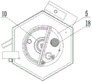
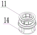
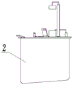
referring to fig. 1-8, a centrifugal mixing tank comprises a frame 1, wherein a mixing tank 2, a distribution box 3 and a control panel 4 are arranged on the frame 1, a half-turning cover type barrel cover 5 is arranged at the top of the mixing tank 2, the half-turning cover type barrel cover 5 comprises a fixed cover 6 and a turning cover 7, and a powdered sugar feeding port 8 and a syrup feeding port 9 are arranged on the fixed cover 6; the bottom of the stirring barrel 2 is inclined and is provided with a centrifugal stirrer 10, the centrifugal stirrer 10 comprises an outer centrifugal stirring blade 11, a turbine-shaped inner centrifugal stirring blade 12, a rotating shaft 13 and a base 14, the outer centrifugal stirring blade 11 is fixedly arranged on the base 14, the inner centrifugal stirring blade 12 is rotatably sleeved on the inner side of the outer centrifugal stirring blade 11, and the bottom of the inner centrifugal stirring blade 12 is connected with a motor 15 through the rotating shaft 13; a discharge port 16 is arranged at the lowest part of the inclined end at the bottom of the stirring barrel 2, and a discharge butterfly valve 17 is arranged at the discharge port 16; the control panel 4, the motor 15 and the discharging butterfly valve 17 are all connected to the distribution box 3. In this embodiment, when equipment uses, the raw materials is thrown into by powdered sugar dog-house 8 and syrup dog-house 9, and after throwing into and finishing, can start centrifugal stirrer 10 by control panel 4 and handle the raw materials, through the cooperation that 2 bottoms slopes of agitator set up, can improve stirring degree of consistency and efficiency, shorten process time, after the stirring is accomplished, can open ejection of compact butterfly valve 17 from control panel 4 equally, derive the raw materials.
Specifically, the sugar powder feeding port 8 and the syrup feeding port 9 are respectively provided with a filter screen 18 for filtering particles. In this implementation, the large granule in the raw materials can be filtered to filter 18, improves the raw materials quality after the stirring, can regularly clear up the granule on the filter screen 18 as required during the use.
Specifically, the reversible cover 7 and the fixed cover 6 are respectively provided with a resisting block 19 and a stop block 20, and when the reversible cover 7 is opened, the resisting block 19 on the reversible cover 7 is buckled on the stop block 20 on the fixed cover 6. In this embodiment, the stopping block 19 and the stopping block 20 are mainly used to limit the turning angle of the turnable cover 7, so as to prevent unnecessary collision and abrasion.
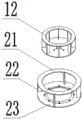
Specifically, the outer centrifugal stirring vane 11 sequentially comprises an upper ring plate 21, four vanes 22 and a lower ring plate 23 from top to bottom, and the vanes 22 are vertically arranged between the upper ring plate 21 and the lower ring plate 23 at equal angles. In this embodiment, the lower ring plate 23 of the outer centrifugal mixing blade 11 is fixed to the base 14, and the inner centrifugal mixing blade 12 is installed in the hollow portion thereof.
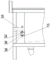
Specifically, still be equipped with the damping device who corresponds agitator 2 in frame 1, damping device includes and sets firmly in the locating piece 24 of 2 outer walls of agitator and sets firmly two linking arms 25 in frame 1, the upper and lower both ends of locating piece 24 all are provided with cushion block 26, it is provided with screw rod 27 to run through between cushion block 26 and the locating piece 24, both ends all are equipped with the lock nut 28 that is used for fixed cushion block 26 about screw rod 27, two linking arms 25 in frame 1 respectively with locating piece 24 and screw rod 27 looks rigid coupling. In this embodiment, the frame 1 is fixed with the side wall of the stirring barrel 2 through the connecting arm 25, and is butted with the positioning block 24 on the outer wall of the stirring barrel 2 in a manner of clamping by the two cushion blocks 26, so that the adjustment is flexible, the vibration amplitude of the barrel body during operation is effectively reduced, and the noise is reduced.
Specifically, a reinforcing rib 29 for reinforcement is arranged between the support legs at the bottom of the frame 1. In this embodiment, the reinforcing ribs 29 are welded to the frame 1, thereby further ensuring the stability thereof.
Specifically, the discharge port 16 is connected with a rotor pump set 30 for pumping materials, and the rotor pump set 30 is connected to the distribution box 3. In this embodiment, the rotor pump unit 30 is connected to the discharge port 16, so that the raw material can be directly pumped out through the rotor pump unit 30 after being stirred.
The above is only the preferred embodiment of the present invention, and all the equivalent changes and modifications made within the scope of the claims of the present invention should belong to the scope of the present invention.
Claims (7)
1. The utility model provides a centrifugal agitator includes the frame, be equipped with agitator, block terminal and control panel in the frame, its characterized in that: the top of the stirring barrel is provided with a half-turning cover type barrel cover, the half-turning cover type barrel cover comprises a fixed cover and a turning cover, and the fixed cover is provided with a powdered sugar feeding port and a syrup feeding port; the bottom of the stirring barrel is inclined and is provided with a centrifugal stirrer, the centrifugal stirrer comprises an outer centrifugal stirring blade, a turbine-shaped inner centrifugal stirring blade, a rotating shaft and a base, the outer centrifugal stirring blade is fixedly arranged on the base, the inner centrifugal stirring blade is rotatably sleeved on the inner side of the outer centrifugal stirring blade, and the bottom of the inner centrifugal stirring blade is connected with a motor through the rotating shaft; a discharge port is arranged at the lowest part of the inclined end at the bottom of the stirring barrel, and a discharge butterfly valve is arranged at the discharge port; and the control panel, the motor and the discharge butterfly valve are all connected to the distribution box.
2. A centrifugal mixing bowl according to claim 1 wherein: and filter screens for filtering particles are arranged at the sugar powder feeding port and the syrup feeding port.
3. A centrifugal mixing bowl according to claim 1 wherein: the turnover cover and the fixed cover are respectively provided with a resisting block and a stop block, and when the turnover cover is opened, the resisting block on the turnover cover is buckled on the stop block on the fixed cover.
4. A centrifugal mixing bowl according to claim 1 wherein: the outer centrifugal stirring blade sequentially comprises an upper annular plate, a plurality of blades and a lower annular plate from top to bottom, and the blades are vertically arranged between the upper annular plate and the lower annular plate at equal angles.
5. A centrifugal mixing bowl according to claim 1 wherein: still be equipped with the damping device who corresponds the agitator in the frame, damping device includes the locating piece that sets firmly in the agitator outer wall and sets firmly two linking arms in the frame, the upper and lower both ends of locating piece all are provided with the cushion block, it is provided with the screw rod to run through between cushion block and the locating piece, both ends all are equipped with the lock nut who is used for fixed cushion block about the screw rod, two linking arms in the frame respectively with locating piece and screw rod looks rigid coupling.
6. A centrifugal mixing bowl according to claim 1 wherein: and reinforcing ribs for reinforcement are arranged between the support legs at the bottom of the rack.
7. A centrifugal mixing bowl according to claim 1 wherein: the discharge port is connected with a rotor pump set used for pumping materials, and the rotor pump set is connected to the distribution box.
Priority Applications (1)
| Application Number | Priority Date | Filing Date | Title |
|---|---|---|---|
| CN202020576360.7U CN212087812U (en) | 2020-04-17 | 2020-04-17 | Centrifugal agitator |
Applications Claiming Priority (1)
| Application Number | Priority Date | Filing Date | Title |
|---|---|---|---|
| CN202020576360.7U CN212087812U (en) | 2020-04-17 | 2020-04-17 | Centrifugal agitator |
Publications (1)
| Publication Number | Publication Date |
|---|---|
| CN212087812U true CN212087812U (en) | 2020-12-08 |
Family
ID=73639937
Family Applications (1)
| Application Number | Title | Priority Date | Filing Date |
|---|---|---|---|
| CN202020576360.7U Active CN212087812U (en) | 2020-04-17 | 2020-04-17 | Centrifugal agitator |
Country Status (1)
| Country | Link |
|---|---|
| CN (1) | CN212087812U (en) |
-
2020
- 2020-04-17 CN CN202020576360.7U patent/CN212087812U/en active Active
Similar Documents
| Publication | Publication Date | Title |
|---|---|---|
| CN110947328A (en) | Mixer for food processing | |
| CN109701861A (en) | A kind of agricultural product plurality of raw materials screening mixing arrangement | |
| CN105233731A (en) | Dried tofu stirring device with automatic feeding function | |
| CN212087812U (en) | Centrifugal agitator | |
| CN205109500U (en) | Dried tofu mixer with automatic material conveying function | |
| CN110339756A (en) | A kind of rabbling mechanism for meat packing | |
| CN209049254U (en) | A kind of sheep raising feed stuff agitating device | |
| CN214514082U (en) | Sesame paste accurate quantitative premixing device | |
| CN216726796U (en) | Agitated vessel is used in lithium ion battery material production and processing | |
| CN213493111U (en) | Agitating unit is used in production of environmental protection adhesive | |
| CN109382031A (en) | A kind of cloth stockline | |
| CN215276986U (en) | Eccentric formula adhesive agitating unit | |
| CN213528285U (en) | Automatic discharging device for rice dumplings | |
| CN208645980U (en) | The stirring of plastic cement semi-finished product, feeding integrated device | |
| CN219540034U (en) | Flour mixing device | |
| CN113117579A (en) | Paint stirrer | |
| CN110813156A (en) | Sweet potato powder mixer | |
| CN217089533U (en) | Automatic curdling equipment for bean product processing | |
| CN217663015U (en) | A agitating unit for agricultural product processing | |
| CN219305892U (en) | Meat product seasoning equipment | |
| CN219502620U (en) | Seasoning powder mixing tank | |
| CN216878894U (en) | Vacuum mixer capable of weighing | |
| CN215540208U (en) | Automatic batching device for zinc oxide production | |
| CN216538253U (en) | Production of salad sauce is with high-efficient emulsification isotropic symmetry | |
| CN211936705U (en) | Be used for white spirit to make raw materials and mix device |
Legal Events
| Date | Code | Title | Description |
|---|---|---|---|
| GR01 | Patent grant | ||
| GR01 | Patent grant |