CN212066808U - Burn scab grinding device - Google Patents
Burn scab grinding device Download PDFInfo
- Publication number
- CN212066808U CN212066808U CN202020247315.7U CN202020247315U CN212066808U CN 212066808 U CN212066808 U CN 212066808U CN 202020247315 U CN202020247315 U CN 202020247315U CN 212066808 U CN212066808 U CN 212066808U
- Authority
- CN
- China
- Prior art keywords
- scab
- fixedly connected
- eschar
- sleeve
- wall
- Prior art date
- Legal status (The legal status is an assumption and is not a legal conclusion. Google has not performed a legal analysis and makes no representation as to the accuracy of the status listed.)
- Expired - Fee Related
Links
Images


Landscapes
- Finish Polishing, Edge Sharpening, And Grinding By Specific Grinding Devices (AREA)
Abstract
The utility model relates to the technical field of medical equipment, and a burn scab grinder is disclosed, including collection scab funnel, support frame fixedly connected with CD-ROM drive motor is passed through in collection scab funnel's left side, and CD-ROM drive motor's output passes through shaft coupling fixedly connected with pivot, and first through-hole has been seted up in collection scab funnel's left side, the inner wall of first through-hole and the surface sliding connection of pivot, the right side fixedly connected with locating piece of pivot. The utility model discloses when polishing, through drive plate and drive belt, it rotates to drive the flabellum, take the air in the second trachea out through the pivoted flabellum, and then make the inside of collecting the scab funnel produce suction, the eschar piece that produces when will polishing is inhaled to first sleeve inside, be convenient for collect the eschar that polishes, simultaneously, also can inhale to first sleeve inside with absorbent eschar piece on the scab cylinder, and then prevent to adsorb on the scab cylinder and have more eschar piece, the effect of polishing that leads to the scab cylinder reduces.
Description
Technical Field
The utility model relates to the technical field of medical equipment, especially, relate to a burn scab ware that grinds.
Background
The wound site typically requires an ablative treatment of the eschar after eschar formation to remove the burned necrotic tissue as quickly as possible. At present, three electric, pneumatic and manual scab grinding tools are mainly used clinically. In the polishing process, eschar fragments generated by polishing directly fall off, so that the eschar fragments are relatively troublesome to collect, and more eschar fragments are easily adsorbed on the burn eschar polisher, so that the polishing effect of the burn eschar polisher is reduced.
SUMMERY OF THE UTILITY MODEL
The purpose of the utility model is to solve the shortcoming that exists among the prior art, if: in the polishing process, eschar fragments generated by polishing directly fall off, so that the collection of the eschar fragments is troublesome, and meanwhile, more eschar fragments are easily adsorbed on the burn eschar polisher, so that the polishing effect of the burn eschar polisher is reduced, and the burn eschar polisher is provided.
In order to achieve the above purpose, the utility model adopts the following technical scheme:
the utility model provides a burn eschar grinding device, includes collection scab funnel, support frame fixedly connected with driving motor is passed through in collection scab funnel's left side, driving motor's output passes through shaft coupling fixedly connected with pivot, first through-hole has been seted up in collection scab funnel's left side, the inner wall of first through-hole and the surperficial sliding connection of pivot, the right side fixedly connected with locating piece of pivot.
The inner wall sliding connection of locating piece has the threaded rod, the surperficial sliding connection of threaded rod has the scab cylinder of grinding, the constant head tank has been seted up on the left side of the scab cylinder of grinding, the inner wall of constant head tank and the surperficial sliding connection of locating piece, the right side fixedly connected with of threaded rod changes the piece, the second through-hole has been seted up on the right side of collection scab funnel, the inner wall of second through-hole and the surperficial sliding connection who changes the piece.
The bottom fixed intercommunication of collection scab funnel has first trachea, first tracheal fixed surface is connected with the connecting plate, the fixed surface of connecting plate is connected with first sleeve, the bottom threaded connection of first sleeve inner wall has sealed lid, the fixed intercommunication in first telescopic left side has the second trachea, the first dust screen of first telescopic inner wall fixedly connected with, first dust screen is located the tracheal right side of second, the tracheal inner wall of second passes through bearing fixedly connected with second sleeve, the telescopic inner wall fixedly connected with flabellum of second, the equal fixedly connected with drive plate in surface of the telescopic surface of second and pivot, the inner wall of drive plate has cup jointed the drive belt.
Preferably, the positioning block is a regular quadrangular block, and the centers of the positioning block, the rotating shaft and the threaded rod are all on the same horizontal line.
Preferably, the maximum distance between the left side of the scab grinding roller and the scab collecting funnel is larger than the thickness of the positioning block.
Preferably, the rotating block is a cylindrical block, the diameter of the rotating block is larger than that of the threaded rod, and the center of the rotating block and the center of the threaded rod are on the same horizontal line.
Preferably, the center of the first air pipe and the center of the first sleeve are on the same vertical line, and the distance between the first air pipe and the sealing cover is 30 mm.
Preferably, a second dust screen is fixedly connected to the left side of the second sleeve.
Compared with the prior art, the beneficial effects of the utility model are that:
(1) the utility model discloses a set up eschar collecting funnel, driving motor, the pivot, first trachea, the connecting plate, first sleeve, sealed lid, the second trachea, first dust screen, first sleeve, the flabellum, drive plate and drive belt, when scab grinds, open driving motor, make scab grinding roller rotate, grind eschar through scab grinding roller, when polishing, through drive plate and drive belt, drive the flabellum and rotate, take out the air in the second trachea through the pivoted flabellum, and then make the inside of scab collecting funnel produce suction, the eschar piece that produces when polishing is inhaled to first sleeve inside, and under the effect of first dust screen, make eschar piece pile up in first sleeve, be convenient for collect the eschar that polishes down, simultaneously, also can inhale the eschar piece that adsorbs on the scab grinding roller to first sleeve inside, and then prevent to have more eschar piece on the scab grinding roller, resulting in a reduced sharpening effect of the sharpening roller.
(2) The utility model discloses a set up locating piece, constant head tank, change piece and threaded rod, insert the locating piece back in the constant head tank, the locating piece plays spacingly to the scab cylinder, makes the scab cylinder follow the pivot and rotate together, simultaneously, through the threaded rod with change the piece, will scab cylinder and locating piece are fixed together, when needs change scab cylinder, rotate and change the piece, separate threaded rod and locating piece, and then can take out the scab cylinder, the medical personnel of being convenient for change or wash the scab cylinder.
Drawings
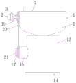
FIG. 1 is a schematic view of the structure of the present invention;
FIG. 2 is a cross-sectional view taken along line A-A of FIG. 1 in accordance with the present invention;
fig. 3 is a front view of the structure of the present invention;
FIG. 4 is a side view of the structure of the present invention;
figure 5 is a side view of the eschar grinding drum of the present invention.
In the figure: 1. a scab collecting funnel; 2. a drive motor; 3. a rotating shaft; 4. a first through hole; 5. positioning blocks; 6. a threaded rod; 7. grinding a scab roller; 8. positioning a groove; 9. rotating the block; 10. a second through hole; 11. a first air pipe; 12. a connecting plate; 13. a first sleeve; 14. a sealing cover; 15. a second air pipe; 16. a first dust screen; 17. a second sleeve; 18. a fan blade; 19. a drive plate; 20. a transmission belt; 21. and a second dust screen.
Detailed Description
The technical solutions in the embodiments of the present invention will be described clearly and completely with reference to the accompanying drawings in the embodiments of the present invention, and it is obvious that the described embodiments are only some embodiments of the present invention, not all embodiments.
In the description of the present invention, it is to be understood that the terms "upper", "lower", "front", "rear", "left", "right", "top", "bottom", "inner", "outer", and the like indicate orientations or positional relationships based on the orientations or positional relationships shown in the drawings, and are only for convenience of description and simplicity of description, and do not indicate or imply that the device or element being referred to must have a particular orientation, be constructed and operated in a particular orientation, and therefore, should not be construed as limiting the present invention.
Referring to fig. 1-5, a burn scab grinding device comprises a scab collecting funnel 1, wherein the left side of the scab collecting funnel 1 is fixedly connected with a driving motor 2 through a support frame, the output end of the driving motor 2 is fixedly connected with a rotating shaft 3 through a coupler, the left side of the scab collecting funnel 1 is provided with a first through hole 4, the inner wall of the first through hole 4 is in sliding connection with the surface of the rotating shaft 3, and the right side of the rotating shaft 3 is fixedly connected with a positioning block 5.
The inner wall of the positioning block 5 is connected with a threaded rod 6 in a sliding manner, the surface of the threaded rod 6 is connected with a scab grinding roller 7 in a sliding manner, the upper surface of the scab grinding roller 7 is higher than the scab collecting funnel 1, the front side and the rear side of the inner wall of the scab collecting funnel 1 and the surface of the scab grinding roller 7 have a moving distance, the surface of the scab grinding roller 7 is provided with more grinding particles, scab is ground by the grinding particles, the left side of the scab grinding roller 7 is provided with a positioning groove 8, the inner wall of the positioning groove 8 is connected with the surface of the positioning block 5 in a sliding manner, the positioning block 5 is a regular four-edge block, the centers of the positioning block 5, the rotating shaft 3 and the threaded rod 6 are all on the same horizontal line, after the positioning block 5 is inserted into the positioning groove 8, the positioning block 5 limits the scab grinding roller 7, the scab grinding roller 7 rotates along with the rotating shaft 3, and, the right side fixedly connected with of threaded rod 6 changes piece 9, back in screwing threaded rod 6 into locating piece 5, through threaded rod 6 and commentaries on classics piece 9, will grind scab cylinder 7 and locating piece 5 and fix together, second through-hole 10 has been seted up on the right side of collection scab funnel 1, the inner wall of second through-hole 10 and the surperficial sliding connection who changes piece 9, change piece 9 and be the cylinder piece, the diameter of changeing piece 9 is greater than the diameter of threaded rod 6, and the center of changeing piece 9 and the center of threaded rod 6 are on same water flat line.
The bottom of the eschar collecting funnel 1 is fixedly communicated with a first air pipe 11, the surface of the first air pipe 11 is fixedly connected with a connecting plate 12, the surface of the connecting plate 12 is fixedly connected with a first sleeve 13, the bottom of the inner wall of the first sleeve 13 is in threaded connection with a sealing cover 14, the center of the first air pipe 11 and the center of the first sleeve 13 are on the same vertical line, the distance between the first air pipe 11 and the sealing cover 14 is 30mm, the left side of the first sleeve 13 is fixedly communicated with a second air pipe 15, the inner wall of the first sleeve 13 is fixedly connected with a first dust screen 16, the first dust screen 16 is positioned on the right side of the second air pipe 15, the first dust screen 16 plays a role in blocking eschar fragments, the eschar fragments are gathered in the first sleeve, the inner wall of the second air pipe 15 is fixedly connected with a second sleeve 17 through a bearing, the inner wall of the second sleeve 17 is fixedly connected with fan blades 18, the left side of the, second dust screen 21 plays the effect of blockking to the dust in the air, prevent that the dust from piling up in second sleeve 17 and the second trachea 15, the equal fixedly connected with drive plate 19 in surface of second sleeve 17 and the surface of pivot 3, drive plate 19's inner wall has cup jointed drive belt 20, drive plate 19's surface has the annular groove, with drive belt 20 card in the annular groove, prevent that drive belt 20 from droing from drive plate 19, through drive belt 20 and drive plate 19, make pivot 3 and second sleeve 17 rotate together.
The utility model discloses in, when the user used the device, open driving motor 2, make eschar cylinder 7 rotate, it polishes the eschar through eschar cylinder 7, in polishing, through drive plate 19 and drive belt 20, it rotates to drive flabellum 18, air in second trachea 15 is taken out through pivoted flabellum 18, and then make the inside of collecting eschar funnel 1 produce suction, eschar piece that will produce when polishing inhales to first sleeve 13 inside, and under the effect of first dust screen 16, make the eschar piece pile up in first sleeve 13, and simultaneously, also can inhale to first sleeve 13 inside with adsorbed eschar piece on eschar cylinder 7, the completion back of polishing, rotate sealed lid 14, separate sealed lid 14 and first sleeve 13, then take out the eschar piece of collecting.
The above, only be the concrete implementation of the preferred embodiment of the present invention, but the protection scope of the present invention is not limited thereto, and any person skilled in the art is in the technical scope of the present invention, according to the technical solution of the present invention and the utility model, the concept of which is equivalent to replace or change, should be covered within the protection scope of the present invention.
It is noted that, herein, relational terms such as first and second, and the like may be used solely to distinguish one entity or action from another entity or action without necessarily requiring or implying any actual such relationship or order between such entities or actions. Also, the terms "comprises," "comprising," or any other variation thereof, are intended to cover a non-exclusive inclusion, such that a process, method, article, or apparatus that comprises a list of elements does not include only those elements but may include other elements not expressly listed or inherent to such process, method, article, or apparatus.
Claims (6)
1. The burn scab grinding device comprises a scab collecting funnel (1), and is characterized in that the left side of the scab collecting funnel (1) is fixedly connected with a driving motor (2) through a support frame, the output end of the driving motor (2) is fixedly connected with a rotating shaft (3) through a coupler, the left side of the scab collecting funnel (1) is provided with a first through hole (4), the inner wall of the first through hole (4) is in sliding connection with the surface of the rotating shaft (3), and the right side of the rotating shaft (3) is fixedly connected with a positioning block (5);
the inner wall of the locating block (5) is connected with a threaded rod (6) in a sliding mode, the surface of the threaded rod (6) is connected with a scab grinding roller (7) in a sliding mode, a locating groove (8) is formed in the left side of the scab grinding roller (7), the inner wall of the locating groove (8) is connected with the surface of the locating block (5) in a sliding mode, a rotating block (9) is fixedly connected to the right side of the threaded rod (6), a second through hole (10) is formed in the right side of the scab collecting funnel (1), and the inner wall of the second through hole (10) is connected with the surface of the rotating block (9);
the bottom of the scab collecting funnel (1) is fixedly communicated with a first air pipe (11), the surface of the first air pipe (11) is fixedly connected with a connecting plate (12), the surface of the connecting plate (12) is fixedly connected with a first sleeve (13), the bottom of the inner wall of the first sleeve (13) is in threaded connection with a sealing cover (14), the left side of the first sleeve (13) is fixedly communicated with a second air pipe (15), the inner wall of the first sleeve (13) is fixedly connected with a first dust screen (16), the first dust screen (16) is positioned on the right side of the second air pipe (15), the inner wall of the second air pipe (15) is fixedly connected with a second sleeve (17) through a bearing, the inner wall of the second sleeve (17) is fixedly connected with fan blades (18), and the surface of the second sleeve (17) and the surface of the rotating shaft (3) are both fixedly connected with a transmission disc (19), the inner wall of the transmission disc (19) is sleeved with a transmission belt (20).
2. A burn eschar grinder according to claim 1, characterized in that the positioning block (5) is a regular quadrangular block, and the centers of the positioning block (5), the rotating shaft (3) and the threaded rod (6) are all on the same horizontal line.
3. A burn eschar abrading device according to claim 1, characterized in that the maximum distance between the left side of the eschar abrading cylinder (7) and the eschar collecting funnel (1) is larger than the thickness of the positioning block (5).
4. A burn eschar grinder as claimed in claim 1, characterized in that the rotary block (9) is a cylindrical block, the diameter of the rotary block (9) is larger than the diameter of the threaded rod (6), and the centre of the rotary block (9) is on the same horizontal line as the centre of the threaded rod (6).
5. A burn eschar grinder according to claim 1, characterized in that the centre of the first air tube (11) is on the same vertical line as the centre of the first sleeve (13), the distance between the first air tube (11) and the sealing cap (14) being 30 mm.
6. A burn eschar grinder according to claim 1, characterized in that a second dust screen (21) is fixedly connected to the left side of the second sleeve (17).
Priority Applications (1)
| Application Number | Priority Date | Filing Date | Title |
|---|---|---|---|
| CN202020247315.7U CN212066808U (en) | 2020-03-03 | 2020-03-03 | Burn scab grinding device |
Applications Claiming Priority (1)
| Application Number | Priority Date | Filing Date | Title |
|---|---|---|---|
| CN202020247315.7U CN212066808U (en) | 2020-03-03 | 2020-03-03 | Burn scab grinding device |
Publications (1)
| Publication Number | Publication Date |
|---|---|
| CN212066808U true CN212066808U (en) | 2020-12-04 |
Family
ID=73559971
Family Applications (1)
| Application Number | Title | Priority Date | Filing Date |
|---|---|---|---|
| CN202020247315.7U Expired - Fee Related CN212066808U (en) | 2020-03-03 | 2020-03-03 | Burn scab grinding device |
Country Status (1)
| Country | Link |
|---|---|
| CN (1) | CN212066808U (en) |
Cited By (1)
| Publication number | Priority date | Publication date | Assignee | Title |
|---|---|---|---|---|
| CN114343788A (en) * | 2022-01-26 | 2022-04-15 | 中国人民解放军陆军军医大学第一附属医院 | Medical burn scab grinding device |
-
2020
- 2020-03-03 CN CN202020247315.7U patent/CN212066808U/en not_active Expired - Fee Related
Cited By (1)
| Publication number | Priority date | Publication date | Assignee | Title |
|---|---|---|---|---|
| CN114343788A (en) * | 2022-01-26 | 2022-04-15 | 中国人民解放军陆军军医大学第一附属医院 | Medical burn scab grinding device |
Similar Documents
| Publication | Publication Date | Title |
|---|---|---|
| CN211305773U (en) | Wall grinding device for construction | |
| CN212066808U (en) | Burn scab grinding device | |
| CN211270487U (en) | Household vertical dust collector | |
| CN215999807U (en) | Press down effectual wall for building engineering and grind flat device | |
| CN211305771U (en) | Wall polisher for construction | |
| CN103846755A (en) | Dustfree wall polisher | |
| CN213730960U (en) | Grinding device is used in chair processing | |
| CN215588654U (en) | Take dust extraction's wall polisher for decoration | |
| CN212145707U (en) | A ground grinds flat equipment for construction | |
| CN205363456U (en) | Polisher from dust collection structure | |
| CN211388183U (en) | Grinding device with crushed aggregates adsorbs and collects function for motor processing | |
| CN212683442U (en) | Hardware polisher | |
| CN218964986U (en) | Handheld dustproof angle grinder | |
| CN208409497U (en) | A kind of new ceramics grinding device | |
| CN218019199U (en) | Mud embryo grinding device for ceramic machining | |
| CN217890158U (en) | Multifunctional luggage pull rod cutting machine | |
| CN206936983U (en) | A kind of interior decoration polishes device with metope | |
| CN212824351U (en) | Putty polisher capable of preventing dust from flying | |
| CN220007209U (en) | Polishing device for stainless steel manufacturing | |
| CN219901448U (en) | Wall grinding device | |
| CN201500917U (en) | Knapsack dust-collection flat grinding machine | |
| CN216179071U (en) | Cement crack repairing sander | |
| CN214292637U (en) | Dust removal device of grinding machine | |
| CN218984183U (en) | Corner grinding device with lifting push rod | |
| CN219599138U (en) | Ash suction device |
Legal Events
| Date | Code | Title | Description |
|---|---|---|---|
| GR01 | Patent grant | ||
| GR01 | Patent grant | ||
| CF01 | Termination of patent right due to non-payment of annual fee |
Granted publication date: 20201204 |
|
| CF01 | Termination of patent right due to non-payment of annual fee |