CN212027313U - Parking device with lifting mechanism - Google Patents
Parking device with lifting mechanism Download PDFInfo
- Publication number
- CN212027313U CN212027313U CN202020292537.0U CN202020292537U CN212027313U CN 212027313 U CN212027313 U CN 212027313U CN 202020292537 U CN202020292537 U CN 202020292537U CN 212027313 U CN212027313 U CN 212027313U
- Authority
- CN
- China
- Prior art keywords
- plate
- fixed mounting
- backup pad
- bottom plate
- lifting mechanism
- Prior art date
- Legal status (The legal status is an assumption and is not a legal conclusion. Google has not performed a legal analysis and makes no representation as to the accuracy of the status listed.)
- Active
Links
Images


Landscapes
- Refuge Islands, Traffic Blockers, Or Guard Fence (AREA)
Abstract
The utility model discloses a parking equipment with elevating system, including bottom plate and backup pad, four angles at bottom plate top have the roof through pole setting fixed mounting, the cover has the backup pad between the pole setting, and the top of backup pad is equipped with the stagnation groove, the bottom fixed mounting of backup pad has two sets of gas cell, fixed mounting has the baffle between the pole setting of backup pad top, the bottom fixed mounting of pole setting outside roof has four hydraulic telescoping rod of group, and hydraulic telescoping rod's output and backup pad fixed connection, the top fixed mounting of pole setting front side bottom plate has the casing. The utility model discloses the condition that the gas cell that sets up can effectually avoid or reduce the vehicle that leads to the below because of the device is out of order to be crushed, and the hydraulic telescoping rod who sets up passes through the hydraulic pump and makes the device realize the operation of going up and down, the effectual actual parking area that has reduced ground has reduced area's consumption, makes its can be better carry out rationalization and utilize, convenient to popularize and use.
Description
Technical Field
The utility model relates to a garage parking technical field specifically is a parking equipment with elevating system.
Background
The stereo garage is a mechanical or mechanical equipment system for storing and taking vehicles to the maximum extent, and is an effective means for improving the capacity of the parking lot and increasing the parking fee income aiming at a professional parking lot management company.
Although the existing parking device achieves basic operation performance, the following defects still exist: 1. traditional parking equipment is only limited to ground, so not only has increased the area of device to reduced the rationalization utilization of soil again, reduced the practicality of device, 2, traditional holistic stability of device is lower simultaneously, and complementary relatively poor, can't be better the stability of having guaranteed the vehicle after parking, consequently need improve to this, in order to solve above-mentioned problem.
SUMMERY OF THE UTILITY MODEL
An object of the utility model is to provide a parking equipment with elevating system is in order to solve the problem that proposes among the above-mentioned background art.
In order to achieve the above object, the utility model provides a following technical scheme: the utility model provides a parking equipment with elevating system, includes bottom plate and backup pad, there is the roof at four angles at bottom plate top through pole setting fixed mounting, the cover has the backup pad between the pole setting, and the top of backup pad is equipped with the stagnation groove, the bottom fixed mounting of backup pad has two sets of gas cell, fixed mounting has the baffle between the pole setting of backup pad top, the bottom fixed mounting of pole setting outside roof has four hydraulic telescoping rod of group, and hydraulic telescoping rod's output and backup pad fixed connection, the top fixed mounting of pole setting front side bottom plate has the casing, and the inside fixed mounting of casing has the hydraulic pump, the backup pad has slope type baffle with the positive all fixed mounting of bottom plate.
Preferably, a sign is fixedly mounted on the front side of the bottom of the top plate.
Preferably, the front face of the shell at the position of the hydraulic pump is fixedly provided with a maintenance plate, and the top of the front face of the shell is fixedly provided with a control switch.
Preferably, the front surface of the baffle is coated with a warning sign.
Preferably, the front sides of the bottom plate and the top of the support plate are both provided with limiting bulges, and the rear side of the top of the support plate is fixedly provided with a guard rail.
Preferably, the bottom fixed mounting of bottom plate has the mounting panel, and the bottom fixed mounting who fixedly mounted has the dowel bottom plate on the mounting panel has the mounting panel, and fixed mounting has the dowel on the mounting panel.
Compared with the prior art, the beneficial effects of the utility model are that: compared with the traditional parking device, the parking device with the lifting mechanism has the advantages that the arranged inflatable bag can effectively avoid or reduce the condition that the vehicle below is crushed due to the failure of the device, the integrity of the vehicle is effectively ensured, the stability during parking is ensured, the practicability of the device is improved, the stability during parking in the air is effectively ensured by the arranged support plate through the stagnation groove, the good limiting effect is achieved, the practicability of the device is improved, the arranged hydraulic telescopic rod enables the device to realize lifting operation through the hydraulic pump, the operation performance of the device is improved, the actual parking area on the ground is effectively reduced, the consumption of the ground area is reduced, the device can be reasonably utilized better, the practicability of the device is improved, the arranged baffle plays a good role in separating, and the condition that the vehicle above the device slides is effectively avoided or reduced, the stability of the vehicle when parking is guaranteed, the practicability is high, and the popularization and the use are convenient.
Drawings
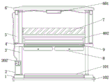
Fig. 1 is a schematic structural diagram of an inner = portion of the present invention;
fig. 2 is a schematic front structural view of the present invention;
fig. 3 is a schematic top view of the present invention.
In the figure: 1. a base plate; 101. a limiting bulge; 102. mounting a plate; 2. a housing; 201. a hydraulic pump; 202. a control switch; 3. erecting a rod; 4. a support plate; 401. a stagnation groove; 402. protecting the fence; 5. a hydraulic telescopic rod; 6. a top plate; 601. a sign; 7. a baffle plate; 8. an air-filled bag; 9. a slope-type guide plate.
Detailed Description
The technical solutions in the embodiments of the present invention will be described clearly and completely with reference to the accompanying drawings in the embodiments of the present invention, and it is obvious that the described embodiments are only some embodiments of the present invention, not all embodiments. Based on the embodiments in the present invention, all other embodiments obtained by a person skilled in the art without creative work belong to the protection scope of the present invention.
In the description of the present invention, it should be noted that the terms "upper", "lower", "inner", "outer", "front end", "rear end", "both ends", "one end", "the other end" and the like indicate orientations or positional relationships based on the orientations or positional relationships shown in the drawings, and are only for convenience of description and simplification of description, but do not indicate or imply that the device or element to which the reference is made must have a specific orientation, be constructed in a specific orientation, and be operated, and thus, should not be construed as limiting the present invention. Furthermore, the terms "first" and "second" are used for descriptive purposes only and are not to be construed as indicating or implying relative importance.
In the description of the present invention, it is to be noted that, unless otherwise explicitly specified or limited, the terms "mounted," "disposed," "connected," and the like are to be construed broadly, and for example, "connected" may be either fixedly connected or detachably connected, or integrally connected; can be mechanically or electrically connected; they may be connected directly or indirectly through intervening media, or they may be interconnected between two elements. The specific meaning of the above terms in the present invention can be understood in specific cases to those skilled in the art.
Referring to fig. 1-3, the present invention provides an embodiment: a parking device with a lifting mechanism comprises a bottom plate 1 and a support plate 4, wherein a baffle 7 is fixedly arranged between upright rods 3 above the support plate 4 through bolts, the baffle 7 plays a good role in separating gears, the sliding of a vehicle above the device is effectively avoided or reduced, the stability of the vehicle during parking is ensured, four groups of hydraulic telescopic rods 5 are fixedly arranged at the bottom of a top plate 6 outside the upright rods 3 through bolts, the output ends of the hydraulic telescopic rods 5 are fixedly connected with the support plate 4 through bolts, a shell 2 is fixedly arranged at the top of the bottom plate 1 at the front side of the upright rods 3 through bolts, a hydraulic pump 201 is fixedly arranged inside the shell 2 through bolts, the type of the hydraulic pump 201 can be an XP-ZCB700AB2A4 hydraulic pump, the hydraulic telescopic rods 5 enable the device to realize lifting operation through the hydraulic pump 201, the operation performance of the device is improved, and the actual parking area on the ground is effectively reduced, the consumption of the ground area is reduced, the ground area can be reasonably utilized better, the practicability of the device is improved, the supporting plate 4 and the front surface of the bottom plate 1 are fixedly welded with the slope-shaped guide plate 9, the slope-shaped guide plate 9 can better ensure that a vehicle is more stable up and down, the safety of the vehicle when the vehicle is parked is ensured, four corners of the top of the bottom plate 1 are fixedly provided with the top plates 6 through the vertical rods 3, the supporting plate 4 is sleeved between the vertical rods 3, the top of the supporting plate 4 is provided with the stagnation groove 401, the stability of the vehicle when the vehicle is parked in the air is effectively ensured through the stagnation groove 401 by the supporting plate 4, the good limiting effect is achieved, the practicability of the device is improved, the bottom of the supporting plate 4 is fixedly provided with two groups of inflatable bags 8 through screws, the inflatable bags 8 can effectively avoid or reduce the condition that the vehicle below is crushed due to the failure of the, the stability when parking is guaranteed, and the practicability of the device is improved.
Further, a sign 601 is fixedly attached to the front side of the bottom of the top plate 6. In the embodiment, the indication board 601 can better record the position information of the device, so that a person can better grasp the vehicle information of the person.
Further, a maintenance board is fixedly mounted on the front surface of the housing 2 at the position of the hydraulic pump 201, and a control switch 202 is fixedly mounted on the top of the front surface of the housing 2. In the embodiment, the maintenance board is convenient for the staff to overhaul the inside apparatus, and control switch 202 passes through wire and hydraulic pump 201 and 5 electric connection of hydraulic telescoping rod, and the staff of being convenient for controls the operation.
Further, the front surface of the baffle 7 is coated with a warning sign. In the embodiment, the baffle 7 can better warn vehicles and pedestrians through the warning mark, and the safety is improved.
Further, the front sides of the tops of the bottom plate 1 and the support plate 4 are both provided with a limiting protrusion 101, and the rear side of the top of the support plate 4 is fixedly provided with a guard rail 402. In the embodiment, the limiting protrusion 101 has a good limiting effect, and can effectively limit the wheels of the vehicle, thereby avoiding or reducing the rolling condition of the vehicle.
Further, a mounting plate 102 is fixedly mounted at the bottom of the bottom plate 1, and a positioning pin is fixedly mounted on the mounting plate 102. In the embodiment, the mounting plate 102 enables the device to be more convenient for workers to mount and fix through the locating pin, and the stability of the device after mounting is ensured.
The working principle is as follows: during operation, the device is fixedly installed through the installation plate 102 on the bottom plate 1, the control switch 202 is connected with an external power supply, the support plate 4 is descended by opening the hydraulic pump 201 and the hydraulic telescopic rod 5, the vehicle parking sub stagnation groove 401 is enabled, then the support plate 4 is ascended, and finally the vehicle is parked on the bottom plate 1.
It is obvious to a person skilled in the art that the invention is not restricted to details of the above-described exemplary embodiments, but that it can be implemented in other specific forms without departing from the spirit or essential characteristics of the invention. The present embodiments are therefore to be considered in all respects as illustrative and not restrictive, the scope of the invention being indicated by the appended claims rather than by the foregoing description, and all changes which come within the meaning and range of equivalency of the claims are therefore intended to be embraced therein. Any reference sign in a claim should not be construed as limiting the claim concerned.
Claims (6)
1. The utility model provides a parking equipment with elevating system, includes bottom plate (1) and backup pad (4), its characterized in that: four corners at the top of the bottom plate (1) are fixedly provided with top plates (6) through upright rods (3), a support plate (4) is sleeved between the upright rods (3), and the top of the supporting plate (4) is provided with a stagnation groove (401), the bottom of the supporting plate (4) is fixedly provided with two groups of inflatable bags (8), a baffle plate (7) is fixedly arranged between the upright rods (3) above the supporting plate (4), four groups of hydraulic telescopic rods (5) are fixedly arranged at the bottom of the top plate (6) at the outer side of the upright rod (3), the output end of the hydraulic telescopic rod (5) is fixedly connected with the supporting plate (4), the top of the front side bottom plate (1) of the upright rod (3) is fixedly provided with a shell (2), and the inside fixed mounting of casing (2) has hydraulic pump (201), the front of backup pad (4) and bottom plate (1) all fixed mounting has slope type baffle (9).
2. The parking apparatus provided with a lifting mechanism according to claim 1, wherein: and a sign (601) is fixedly mounted on the front side of the bottom of the top plate (6).
3. The parking apparatus provided with a lifting mechanism according to claim 1, wherein: the front face of the shell (2) at the position of the hydraulic pump (201) is fixedly provided with a maintenance plate, and the top of the front face of the shell (2) is fixedly provided with a control switch (202).
4. The parking apparatus provided with a lifting mechanism according to claim 1, wherein: the front surface of the baffle (7) is coated with a warning sign.
5. The parking apparatus provided with a lifting mechanism according to claim 1, wherein: the front sides of the tops of the bottom plate (1) and the supporting plate (4) are provided with limiting protrusions (101), and the rear side of the top of the supporting plate (4) is fixedly provided with a protective guard (402).
6. The parking apparatus provided with a lifting mechanism according to claim 1, wherein: the bottom of bottom plate (1) is fixed mounting has mounting panel (102), and fixed mounting has the locating pin on mounting panel (102).
Priority Applications (1)
| Application Number | Priority Date | Filing Date | Title |
|---|---|---|---|
| CN202020292537.0U CN212027313U (en) | 2020-03-11 | 2020-03-11 | Parking device with lifting mechanism |
Applications Claiming Priority (1)
| Application Number | Priority Date | Filing Date | Title |
|---|---|---|---|
| CN202020292537.0U CN212027313U (en) | 2020-03-11 | 2020-03-11 | Parking device with lifting mechanism |
Publications (1)
| Publication Number | Publication Date |
|---|---|
| CN212027313U true CN212027313U (en) | 2020-11-27 |
Family
ID=73484932
Family Applications (1)
| Application Number | Title | Priority Date | Filing Date |
|---|---|---|---|
| CN202020292537.0U Active CN212027313U (en) | 2020-03-11 | 2020-03-11 | Parking device with lifting mechanism |
Country Status (1)
| Country | Link |
|---|---|
| CN (1) | CN212027313U (en) |
-
2020
- 2020-03-11 CN CN202020292537.0U patent/CN212027313U/en active Active
Similar Documents
| Publication | Publication Date | Title |
|---|---|---|
| CN212027313U (en) | Parking device with lifting mechanism | |
| CN210712623U (en) | Traffic snapshot device with telescopic mechanism | |
| CN218893999U (en) | Warning device for highway engineering construction | |
| CN215068636U (en) | Signal lamp device for smart city construction | |
| CN216074875U (en) | Electric and manual combined lifting column | |
| CN212609394U (en) | Distribution maintenance is with overhauing auxiliary device | |
| CN218842917U (en) | Highway maintenance construction vehicle warning device | |
| CN220978993U (en) | Stereo garage operation panel | |
| CN221632055U (en) | Scenic spot weather early warning device | |
| CN219122734U (en) | Substation operation inspection instrument | |
| CN221261804U (en) | Solar traffic emergency indicator lamp | |
| CN219989014U (en) | Support protection mechanism for charger | |
| CN219344204U (en) | Safety device for car carrying plate of stereo garage | |
| CN219124261U (en) | Movable monitoring device | |
| CN212481110U (en) | Movable street lamp | |
| CN221315858U (en) | Integral type removes fills electric pile | |
| CN216108180U (en) | A sign for road bridge safety warning | |
| CN218413734U (en) | Novel traffic signal sign board for urban road | |
| CN220569269U (en) | Temporary traffic signal lamp used in road construction | |
| CN212208546U (en) | Traffic information acquisition device | |
| CN215934785U (en) | Photovoltaic installing support with adjustable multi-angle | |
| CN218732722U (en) | Outdoor corrosion-resistant box-type substation | |
| CN213951789U (en) | Multifunctional construction vehicle for subway rail | |
| CN217382320U (en) | Urban rail transit monitoring device | |
| CN218537135U (en) | Unmanned aerial vehicle survey and drawing data acquisition device |
Legal Events
| Date | Code | Title | Description |
|---|---|---|---|
| GR01 | Patent grant | ||
| GR01 | Patent grant |