CN212609394U - Distribution maintenance is with overhauing auxiliary device - Google Patents
Distribution maintenance is with overhauing auxiliary device Download PDFInfo
- Publication number
- CN212609394U CN212609394U CN202021070876.0U CN202021070876U CN212609394U CN 212609394 U CN212609394 U CN 212609394U CN 202021070876 U CN202021070876 U CN 202021070876U CN 212609394 U CN212609394 U CN 212609394U
- Authority
- CN
- China
- Prior art keywords
- plate
- seat
- auxiliary device
- connecting plate
- connecting block
- Prior art date
- Legal status (The legal status is an assumption and is not a legal conclusion. Google has not performed a legal analysis and makes no representation as to the accuracy of the status listed.)
- Active
Links
Images


Abstract
The utility model discloses a distribution maintenance is with overhauing auxiliary device, including the locomotive, install supporting mechanism on the locomotive, the locomotive top is provided with elevating system, elevating system includes mount pad, connecting plate, motor, be provided with on the mount pad the connecting plate, the terminal surface is installed under the connecting plate the motor, the connecting plate up end is provided with the draw bar, draw bar one side is provided with the lead screw, install the lift seat on the lead screw, lift seat front portion is provided with the backup plate, the backup plate front portion is provided with the seat, the safety belt is installed to the seat top. The utility model discloses simple structure, reasonable in design, low in production cost, very big convenience goes up and down to the workman, increases travelling comfort and security simultaneously, and the convenience is maintained the block terminal, and the practicality is high.
Description
Technical Field
The utility model relates to a distribution maintenance technical field especially relates to a distribution maintenance is with overhauing auxiliary device.
Background
The distribution box is a mass parameter on data, generally forms a low-voltage forest according to electrical wiring, and requires that a switch device, a measuring instrument, a protective electrical appliance and an auxiliary device are assembled in a closed or semi-closed metal cabinet or on a screen to form the low-voltage distribution box. In normal operation, the circuit can be switched on or off by means of a manual or automatic switch.
The distribution box has the characteristics of small volume, simple and convenient installation, special technical performance, fixed position, unique configuration function, no field limitation, universal application, stable and reliable operation, high space utilization rate, less occupied area and environmental protection effect. The intelligent power distribution circuit can reasonably distribute electric energy, is convenient for opening and closing the circuit, has higher safety protection level, and can visually display the conduction state of the circuit.
In the block terminal maintenance process, some block terminals are higher, and the workman all maintains through the ladder usually, and is not only inconvenient like this, has the potential safety hazard moreover.
SUMMERY OF THE UTILITY MODEL
An object of the utility model is to provide a distribution maintenance is with overhauing auxiliary device just in order to solve above-mentioned problem.
The utility model discloses a following technical scheme realizes above-mentioned purpose:
the utility model provides a distribution maintenance is with overhauing auxiliary device, includes the locomotive, install supporting mechanism on the locomotive, the locomotive top is provided with elevating system, elevating system includes mount pad, connecting plate, motor, be provided with on the mount pad the connecting plate, the terminal surface is installed under the connecting plate the motor, the connecting plate up end is provided with the smooth rod, smooth rod one side is provided with the lead screw, install the lift seat on the lead screw, lift seat front portion is provided with the backup plate, the backup plate front portion is provided with the seat, the safety belt is installed to the seat top, the safety belt top is provided with the handrail, install the toolbox on the handrail.
As a further aspect of the present invention, the support mechanism includes a retractable plate, a connecting block, and a support pillar, the retractable plate is provided with the connecting block, and the lower end surface of the connecting block is provided with the support pillar.
As a further scheme of the utility model, supporting mechanism includes electronic flexible post, connecting block, pillar, install on the electronic flexible post the connecting block, the terminal surface is provided with under the connecting block the pillar.
As a further aspect of the present invention, the connecting plate is welded to the mounting seat, and the motor is connected to the screw rod through a coupling.
As a further aspect of the present invention, the lifting seat is connected to the sliding bar in a sliding manner, the backup plate is welded to the lifting seat, and the seat plate is welded to the backup plate.
As a further proposal of the utility model, the sliding bar is welded on the upper end face of the connecting plate, and the upper end face of the seat plate is provided with a layer of spongy cushion.
As a further aspect of the present invention, the connecting block is installed through a bolt at the front end of the expansion plate.
Compared with the prior art, the beneficial effects of the utility model are that: through setting up elevating system and supporting mechanism, very big convenience goes up and down to the workman, increases travelling comfort and security simultaneously, and the convenience is maintained the block terminal, and the practicality is high.
Drawings
In order to more clearly illustrate the embodiments of the present invention or the technical solutions in the prior art, the drawings needed to be used in the description of the embodiments or the prior art will be briefly described below, it is obvious that the drawings in the following description are only some embodiments of the present invention, and for those skilled in the art, other drawings can be obtained according to these drawings without inventive exercise.
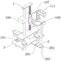
Fig. 1 is a perspective view of an embodiment 1 of an inspection and repair auxiliary device for power distribution maintenance according to the present invention;
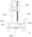
fig. 2 is a front view of an embodiment 1 of an inspection and repair auxiliary device for power distribution maintenance according to the present invention;
fig. 3 is a left side view of an embodiment 1 of an overhaul auxiliary device for power distribution maintenance according to the present invention;
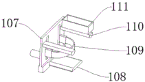
fig. 4 is a schematic structural view of a backup plate according to embodiment 1 of the maintenance auxiliary device for power distribution maintenance of the present invention;
fig. 5 is a schematic diagram of the supporting mechanism of embodiment 2 of the maintenance assisting device for power distribution maintenance.
The reference numerals are explained below:
1. a lifting mechanism; 2. a support mechanism; 3. a mobile vehicle; 101. a mounting seat; 102. a connecting plate; 103. a motor; 104. a slide bar; 105. a lead screw; 106. a lifting seat; 107. a backup plate; 108. a seat plate; 109. a seat belt; 110. a handrail; 111. a tool box; 201. a retractable plate; 202. connecting blocks; 203. a pillar; 204. electric telescopic column.
Detailed Description
In the description of the present invention, it is to be understood that the terms "center", "longitudinal", "lateral", "up", "down", "front", "back", "left", "right", "vertical", "horizontal", "top", "bottom", "inner", "outer", and the like, indicate orientations or positional relationships based on the orientations or positional relationships shown in the drawings, and are used merely for convenience of description and for simplicity of description, and do not indicate or imply that the device or element being referred to must have a particular orientation, be constructed and operated in a particular orientation, and therefore, should not be construed as limiting the present invention. Furthermore, the terms "first", "second", etc. are used for descriptive purposes only and are not to be construed as indicating or implying relative importance or implicitly indicating the number of technical features indicated. Thus, a feature defined as "first," "second," etc. may explicitly or implicitly include one or more of that feature. In the description of the present invention, "a plurality" means two or more unless otherwise specified.
In the description of the present invention, it is to be noted that, unless otherwise explicitly specified or limited, the terms "mounted," "connected," and "connected" are to be construed broadly, and may be, for example, fixedly connected, detachably connected, or integrally connected; can be mechanically or electrically connected; they may be connected directly or indirectly through intervening media, or they may be interconnected between two elements. The specific meaning of the above terms in the present invention can be understood by those of ordinary skill in the art through specific situations.
The present invention will be further explained with reference to the accompanying drawings.
Example 1
As shown in fig. 1, fig. 2, fig. 3 and fig. 4, the utility model provides a technical solution: the utility model provides a distribution maintenance is with overhauing auxiliary device, including locomotive 3, install supporting mechanism 2 on the locomotive 3, locomotive 3 top is provided with elevating system 1, elevating system 1 includes mount pad 101, connecting plate 102, motor 103, be provided with connecting plate 102 on the mount pad 101, motor 103 is installed to the terminal surface under the connecting plate 102, the connecting plate 102 up end is provided with slide bar 104, slide bar 104 one side is provided with lead screw 105, install lift seat 106 on the lead screw 105, lift seat 106 front portion is provided with backup plate 107, backup plate 107 front portion is provided with seat 108, safety belt 109 is installed to seat 108 top, safety belt 109 top is provided with handrail 110, install toolbox 111 on handrail 110.
On the basis of the above-described embodiment: the supporting mechanism 2 comprises a telescopic plate 201, a connecting block 202 and a strut 203, wherein the connecting block 202 is mounted on the telescopic plate 201, and the strut 203 is arranged on the lower end face of the connecting block 202; the connecting plate 102 is welded with the mounting seat 101, and the motor 103 is connected with the lead screw 105 through a coupler; the lifting seat 106 is connected with the sliding bar 104 in a sliding manner, the backup plate 107 is welded on the lifting seat 106, and the seat plate 108 is welded with the backup plate 107; the sliding bar 104 is welded on the upper end surface of the connecting plate 102, and a layer of sponge cushion is arranged on the upper end surface of the seat plate 108; the connecting block 202 is mounted at the front end of the expansion plate 201 through bolts.
The working principle is as follows: move the device to suitable place through locomotive 3, then lengthen expansion plate 201, make pillar 203 place in ground, increase the lifting surface area, guarantee the stability of device, then the workman sits on seat 108, lean against backup plate 107, fix safety belt 109 between the waist, can place repair tools in toolbox 111, then motor 103 drives lead screw 105 and rotates, make lift seat 106 rise along slide bar 104, it rises to drive backup plate 107, rise the workman to suitable height after, begin to maintain the switch board.
Example 2
As shown in fig. 5, embodiment 2 differs from embodiment 1 in that the support mechanism 2 includes an electric telescopic column 204, a connecting block 202, and a support column 203, the connecting block 202 is mounted on the electric telescopic column 204, and the support column 203 is provided on the lower end surface of the connecting block 202.
The extension of the telescopic plate 201 by hand is changed into the automatic extension of the electric telescopic column 204.
The foregoing illustrates and describes the principles, general features, and advantages of the present invention. It will be understood by those skilled in the art that the present invention is not limited to the above embodiments, and that the foregoing embodiments and descriptions are provided only to illustrate the principles of the present invention without departing from the spirit and scope of the present invention.
Claims (7)
1. The utility model provides a distribution maintenance is with overhauing auxiliary device, includes locomotive (3), its characterized in that: a supporting mechanism (2) is arranged on the moving vehicle (3), a lifting mechanism (1) is arranged above the moving vehicle (3), the lifting mechanism (1) comprises a mounting seat (101), a connecting plate (102) and a motor (103), the mounting seat (101) is provided with the connecting plate (102), the lower end face of the connecting plate (102) is provided with the motor (103), a sliding bar (104) is arranged on the upper end surface of the connecting plate (102), a screw rod (105) is arranged on one side of the sliding bar (104), a lifting seat (106) is arranged on the screw rod (105), a backup plate (107) is arranged at the front part of the lifting seat (106), a seat plate (108) is arranged at the front part of the backup plate (107), a safety belt (109) is arranged above the seat plate (108), an armrest (110) is arranged above the safety belt (109), and a tool box (111) is mounted on the armrest (110).
2. An overhaul auxiliary device for power distribution maintenance according to claim 1, wherein: the supporting mechanism (2) comprises a telescopic plate (201), a connecting block (202) and a supporting column (203), the connecting block (202) is installed on the telescopic plate (201), and the supporting column (203) is arranged on the lower end face of the connecting block (202).
3. An overhaul auxiliary device for power distribution maintenance according to claim 1, wherein: the supporting mechanism (2) comprises an electric telescopic column (204), a connecting block (202) and a supporting column (203), the connecting block (202) is installed on the electric telescopic column (204), and the supporting column (203) is arranged on the lower end face of the connecting block (202).
4. An overhaul auxiliary device for power distribution maintenance according to claim 1, wherein: the connecting plate (102) is welded with the mounting seat (101), and the motor (103) is connected with the lead screw (105) through a coupler.
5. An overhaul auxiliary device for power distribution maintenance according to claim 1, wherein: the lifting seat (106) is connected with the sliding bar (104) in a sliding mode, the backup plate (107) is welded to the lifting seat (106), and the seat plate (108) is welded to the backup plate (107).
6. An overhaul auxiliary device for power distribution maintenance according to claim 1, wherein: the sliding bar (104) is welded on the upper end face of the connecting plate (102), and a layer of sponge cushion is arranged on the upper end face of the seat plate (108).
7. An inspection and repair assistance device for power distribution maintenance according to claim 2, characterized in that: the connecting block (202) is installed at the front end of the expansion plate (201) through a bolt.
Priority Applications (1)
| Application Number | Priority Date | Filing Date | Title |
|---|---|---|---|
| CN202021070876.0U CN212609394U (en) | 2020-06-11 | 2020-06-11 | Distribution maintenance is with overhauing auxiliary device |
Applications Claiming Priority (1)
| Application Number | Priority Date | Filing Date | Title |
|---|---|---|---|
| CN202021070876.0U CN212609394U (en) | 2020-06-11 | 2020-06-11 | Distribution maintenance is with overhauing auxiliary device |
Publications (1)
| Publication Number | Publication Date |
|---|---|
| CN212609394U true CN212609394U (en) | 2021-02-26 |
Family
ID=74715738
Family Applications (1)
| Application Number | Title | Priority Date | Filing Date |
|---|---|---|---|
| CN202021070876.0U Active CN212609394U (en) | 2020-06-11 | 2020-06-11 | Distribution maintenance is with overhauing auxiliary device |
Country Status (1)
| Country | Link |
|---|---|
| CN (1) | CN212609394U (en) |
-
2020
- 2020-06-11 CN CN202021070876.0U patent/CN212609394U/en active Active
Similar Documents
| Publication | Publication Date | Title |
|---|---|---|
| CN209929856U (en) | Quick overhaul device that electric wire netting control was used | |
| CN212609394U (en) | Distribution maintenance is with overhauing auxiliary device | |
| CN213125120U (en) | Wall body articulates formula switch board convenient to maintenance | |
| CN210309475U (en) | Adjusting device for CTP plate-making machine | |
| CN209865201U (en) | Psychological behavior training device | |
| CN209974202U (en) | Power equipment installation insulating frame capable of being installed quickly | |
| CN212626528U (en) | Ring main unit electric operating mechanism | |
| CN216016124U (en) | Supporting mechanism of switch cabinet electrical automation equipment | |
| CN217269173U (en) | Be applied to stereo garage's fill electric pile structure | |
| CN214899795U (en) | Fuse arrester handcart | |
| CN218620167U (en) | Current transformer lifts by crane installation device | |
| CN213416111U (en) | Vehicle-mounted electric jack | |
| CN213520801U (en) | Power distribution cabinet with protective device | |
| CN213185172U (en) | Electric motor car block terminal fixing device | |
| CN210181896U (en) | Building electrical wiring display device | |
| CN211551453U (en) | Solar energy navigation warning light | |
| CN220747889U (en) | Electrician uses safety device | |
| CN212011883U (en) | Auxiliary device for electrical overhaul | |
| CN218509395U (en) | Stable in structure's electric power overhaul ladder | |
| CN216634318U (en) | Nonporous lifting rotary tool platform of insulating bucket arm vehicle | |
| CN216383402U (en) | Console based on artificial intelligence | |
| CN214898216U (en) | Auxiliary operating mechanism of high-voltage alternating-current isolating switch operating mechanism box | |
| CN218632872U (en) | Outdoor sealed power distribution cabinet | |
| CN214695267U (en) | Novel traffic engineering direction tablet | |
| CN217281640U (en) | Block terminal convenient to installation with mounting bracket |
Legal Events
| Date | Code | Title | Description |
|---|---|---|---|
| GR01 | Patent grant | ||
| GR01 | Patent grant |