CN211991810U - Five-axis machining platform of line is walked to single armed cavity - Google Patents
Five-axis machining platform of line is walked to single armed cavity Download PDFInfo
- Publication number
- CN211991810U CN211991810U CN202020415303.0U CN202020415303U CN211991810U CN 211991810 U CN211991810 U CN 211991810U CN 202020415303 U CN202020415303 U CN 202020415303U CN 211991810 U CN211991810 U CN 211991810U
- Authority
- CN
- China
- Prior art keywords
- arm
- driving mechanism
- hollow
- cavity
- motor
- Prior art date
- Legal status (The legal status is an assumption and is not a legal conclusion. Google has not performed a legal analysis and makes no representation as to the accuracy of the status listed.)
- Active
Links
Images

Abstract
The utility model discloses a single-arm hollow wiring five-axis machining table, which comprises a first driving mechanism, a second driving mechanism, a rotating arm and a rotating table, wherein one end of the rotating arm is synchronously connected with the power output end of the first driving mechanism; the first driving mechanism is used for driving the rotating arm to rotate around a horizontal shaft; the rotary table is pivoted to the end part of the rotating arm far away from the first driving mechanism; the second driving mechanism is arranged on the rotating arm and is used for driving the rotary table to rotate around the vertical shaft; the rotating arm is internally provided with a hollow wiring cavity, and a power line of the second driving mechanism penetrates through the hollow wiring cavity. The utility model discloses a five-axis machining platform of line are walked to single armed cavity, its rotatable platform is exported by the single armed in the rotation of horizontal direction, increases the moment of torsion, and the cavity of being equipped with is walked the line chamber and is convenient for walk the line.
Description
Technical Field
The utility model relates to the technical field of machining, especially, relate to a five-axis machining platform of line are walked to single armed cavity.
Background
At present, a five-axis numerical control machine tool is a machine tool which has high technological content and high precision and is specially used for machining complex curved surfaces. The driving device on the existing machine tool drives the rotary table to do linear motion in the directions of an X axis, a Y axis and a Z axis, the rotary table is usually rotated by the X axis output by a motor and is matched with the rotation of the Z axis output by the motor, the two motors are usually in direct connection, the torque is small, the jamming is easy to occur, and the line winding is easy to cause, so that the processing progress is influenced.
SUMMERY OF THE UTILITY MODEL
In order to overcome the defects of the prior art, the utility model aims to provide a five-axis machining platform of line is walked to single armed cavity, its rotatable platform is exported by the single armed at the rotation of horizontal direction, increases the moment of torsion, and the cavity of being equipped with is walked the line chamber and is convenient for walk the line.
The purpose of the utility model is realized by adopting the following technical scheme:
a single-arm hollow wiring five-axis machining table comprises a first driving mechanism, a second driving mechanism, a rotating arm and a rotating table, wherein one end of the rotating arm is synchronously connected with a power output end of the first driving mechanism; the first driving mechanism is used for driving the rotating arm to rotate around a horizontal shaft; the rotary table is pivoted to the end part of the rotating arm far away from the first driving mechanism; the second driving mechanism is arranged on the rotating arm and is used for driving the rotary table to rotate around the vertical shaft; the rotating arm is internally provided with a hollow wiring cavity, and a power line of the second driving mechanism penetrates through the hollow wiring cavity.
Preferably, the rotating arm comprises a connecting arm and a mounting arm, and the top end of the connecting arm is synchronously connected with the power output end of the first driving mechanism; the mounting arm is vertically and fixedly connected to the bottom end of the connecting arm, and the second driving mechanism and the rotary table are mounted on the mounting arm; a first hollow cavity is arranged on the connecting arm; the mounting arm is provided with a second hollow cavity, and the first hollow cavity and the second hollow cavity are communicated with each other to form the hollow wiring cavity.
Preferably, the first driving mechanism comprises a first motor and a speed reducer, and a machine body of the first motor is connected with a machine body of the speed reducer through a flange plate; a rotating shaft of the first motor is synchronously connected with the input end of the speed reducer; the output end of the speed reducer is connected with the connecting arm.
Preferably, a third hollow cavity is arranged on the speed reducer body, and the first hollow cavity, the second hollow cavity and the third hollow cavity are communicated with each other to form the hollow wiring cavity.
Preferably, the second driving mechanism comprises a second motor, the body of the second motor is connected to the bottom end of the mounting arm, and the rotating shaft of the second motor extends out of the top end of the mounting arm and is fixed with the turntable.
Preferably, a protective cover is arranged on the mounting arm, and the protective cover is arranged outside the machine body of the second motor and is detachably fixed with the mounting arm.
Preferably, a plurality of mounting holes are formed in the turntable.
Compared with the prior art, the beneficial effects of the utility model reside in that: the rotation of the rotary table in the horizontal direction is output by the single arm to drive the rotary table on the single arm to rotate, so that the torque is increased, the rotation of the rotary table in the vertical direction can be driven by the second driving mechanism, and the arranged hollow wiring cavity is convenient for wiring.
Drawings
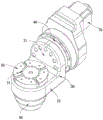
Fig. 1 is a schematic structural view of the present invention;
fig. 2 is a cross-sectional view of the present invention.
In the figure: 10. a first motor; 20. a rotating arm; 21. a connecting arm; 211. a first hollow cavity; 22. mounting an arm; 221. a second hollow cavity; 30. a turntable; 31. mounting holes; 40. a speed reducer; 41. a third hollow cavity; 50. a protective cover; 60. a second motor.
Detailed Description
The invention will be further described with reference to the accompanying drawings and specific embodiments:
as shown in fig. 1 and 2, the single-arm hollow routing five-axis machining table includes a first driving mechanism, a second driving mechanism, a rotating arm 20 and a turntable 30, wherein one end of the rotating arm 20 is synchronously connected with a power output end of the first driving mechanism, and the first driving mechanism can drive the rotating arm 20 to rotate around a horizontal axis. In addition, the turntable 30 is pivotally connected to the end of the rotatable arm 20 remote from the first drive mechanism, and the second drive mechanism is mounted on the rotatable arm 20 and is capable of rotating the turntable 30 about the vertical axis. A hollow wiring cavity is formed in the rotating arm 20, and a power line of the second driving mechanism is connected to the hollow wiring cavity in a penetrating manner.
On the basis of the structure, use the utility model discloses a five-axis machining platform of line is walked to single armed cavity installs this processing platform on the digit control machine tool, and linear motion output device on the digit control machine tool can drive the processing platform and be linear motion at X axle, Y axle and Z axle, moves corresponding cutter department. The workpiece is clamped on the rotary table 30, the first driving mechanism can drive the rotary arm 20 to rotate in the horizontal direction, the rotation of the rotary table 30 in the horizontal direction is output by a single arm, the torque is increased, and a cutter on a numerical control machine can machine the workpiece in the circumferential direction of the horizontal direction. The second driving mechanism can drive the rotary table 30 to rotate in the vertical direction, and the cutter on the numerical control machine tool can machine the workpiece in the circumferential direction of the workpiece in the vertical direction. In addition, the hollow wiring cavity is arranged to facilitate wiring.
Specifically, in the present embodiment, the rotating arm 20 includes a connecting arm 21 and a mounting arm 22, wherein the top end of the connecting arm 21 is synchronously coupled with the power output end of the first driving mechanism, and the mounting arm 22 is vertically and fixedly connected to the bottom end of the connecting arm 21. The second driving mechanism and the turntable 30 are both mounted on the mounting arm 22; the connecting arm 21 is provided with a first hollow cavity 211; the mounting arm 22 is provided with a second hollow cavity 221, and the first hollow cavity 211 and the second hollow cavity 221 are communicated with each other to form a hollow wiring cavity.
In performing power output, the connecting arm 21 of the boom 20 is coupled to the power output end of the first driving mechanism, and the second driving mechanism and the turntable 30 are mounted on the mounting arm 22 perpendicular to the connecting arm 21, i.e., mounted separately from the power output, and operated separately, and the second driving mechanism and the turntable 30 have a sufficiently large mounting space. When the wire is routed, the second driving mechanism can penetrate through the first hollow cavity 211 through the second hollow shaft, so as to prevent the wire from winding in the rotating process.
Preferably, the first driving mechanism includes a first motor 10 and a speed reducer 40, and the body of the first motor 10 is connected to the body of the speed reducer 40 through a flange, and is connected through a flange, so as to facilitate the detachment and installation between the first motor 10 and the speed reducer 40. On the basis of the structure, the rotating shaft of the first motor 10 is synchronously connected with the input end of the speed reducer 40; the output end of the speed reducer 40 is connected with the connecting arm 21, so that the rotating shaft transmission of the first motor 10 can be reduced by the speed reducer 40 and output stably.
Preferably, the body of the speed reducer 40 is provided with a third hollow cavity 41, and the first hollow cavity 211, the second hollow cavity 221 and the third hollow cavity 41 are mutually communicated to form a hollow wiring cavity, that is, in the case of the speed reducer 40, a circuit of the second driving mechanism can pass through the second hollow cavity 221 and the first hollow cavity 211 and pass through the speed reducer 40.
Preferably, the second driving mechanism includes a second motor 60, the body of the second motor 60 is connected to the bottom end of the mounting arm 22, the rotating shaft of the second motor 60 extends from the top end of the mounting arm 22 and is fixed to the turntable 30, and the second motor 60 can directly drive the turntable 30 to rotate, which is simple in structure.
Further, the protective cover 50 is disposed on the mounting arm 22, the protective cover 50 covers the exterior of the second motor 60 and is detachably fixed to the mounting arm 22, and the protective cover 50 may be fixedly connected to the mounting arm 22 through a screw, so as to facilitate maintenance of the second motor 60. The protective cover 50 is covered outside the second motor 60 to protect the second motor 60, so as to prevent dust and water.
Preferably, the turntable 30 is provided with a plurality of mounting holes 31, the plurality of mounting holes 31 can directly clamp the workpiece on the turntable 30 through bolts, or clamp the workpiece on the turntable 30 through bolts, and the clamp can clamp the workpiece, so that the workpiece can be conveniently mounted.
Various other modifications and changes may be made by those skilled in the art based on the above-described technical solutions and concepts, and all such modifications and changes are intended to fall within the scope of the claims.
Claims (7)
1. A single-arm hollow wiring five-axis machining table is characterized by comprising a first driving mechanism, a second driving mechanism, a rotating arm and a rotating table, wherein one end of the rotating arm is synchronously connected with a power output end of the first driving mechanism; the first driving mechanism is used for driving the rotating arm to rotate around a horizontal shaft; the rotary table is pivoted to the end part of the rotating arm far away from the first driving mechanism; the second driving mechanism is arranged on the rotating arm and is used for driving the rotary table to rotate around the vertical shaft; the rotating arm is internally provided with a hollow wiring cavity, and a power line of the second driving mechanism penetrates through the hollow wiring cavity.
2. The single-arm hollow routing five-axis machining table according to claim 1, wherein the rotating arm comprises a connecting arm and a mounting arm, and the top end of the connecting arm is synchronously coupled with the power output end of the first driving mechanism; the mounting arm is vertically and fixedly connected to the bottom end of the connecting arm, and the second driving mechanism and the rotary table are mounted on the mounting arm; a first hollow cavity is arranged on the connecting arm; the mounting arm is provided with a second hollow cavity, and the first hollow cavity and the second hollow cavity are communicated with each other to form the hollow wiring cavity.
3. The five-axis machining table of single-arm hollow routing of claim 2, wherein the first driving mechanism comprises a first motor and a speed reducer, and a body of the first motor is connected with a body of the speed reducer through a flange; a rotating shaft of the first motor is synchronously connected with the input end of the speed reducer; the output end of the speed reducer is connected with the connecting arm.
4. The five-axis machining table for single-arm hollow routing of claim 3, wherein a body of the speed reducer is provided with a third hollow cavity, and the first hollow cavity, the second hollow cavity and the third hollow cavity are communicated with each other to form the hollow routing cavity.
5. The five-axis single-arm hollow routing machining table according to claim 2, wherein the second driving mechanism comprises a second motor, a body of the second motor is connected to the bottom end of the mounting arm, and a rotating shaft of the second motor extends out of the top end of the mounting arm and is fixed to the turntable.
6. The five-axis machining table of hollow wire of single-arm of claim 5, wherein a protection cover is provided on the mounting arm, and the protection cover is provided outside the body of the second motor and detachably fixed with the mounting arm.
7. The five-axis single-arm hollow routing machining table according to claim 1, wherein a plurality of mounting holes are formed in the turntable.
Priority Applications (1)
| Application Number | Priority Date | Filing Date | Title |
|---|---|---|---|
| CN202020415303.0U CN211991810U (en) | 2020-03-26 | 2020-03-26 | Five-axis machining platform of line is walked to single armed cavity |
Applications Claiming Priority (1)
| Application Number | Priority Date | Filing Date | Title |
|---|---|---|---|
| CN202020415303.0U CN211991810U (en) | 2020-03-26 | 2020-03-26 | Five-axis machining platform of line is walked to single armed cavity |
Publications (1)
| Publication Number | Publication Date |
|---|---|
| CN211991810U true CN211991810U (en) | 2020-11-24 |
Family
ID=73422323
Family Applications (1)
| Application Number | Title | Priority Date | Filing Date |
|---|---|---|---|
| CN202020415303.0U Active CN211991810U (en) | 2020-03-26 | 2020-03-26 | Five-axis machining platform of line is walked to single armed cavity |
Country Status (1)
| Country | Link |
|---|---|
| CN (1) | CN211991810U (en) |
Cited By (1)
| Publication number | Priority date | Publication date | Assignee | Title |
|---|---|---|---|---|
| CN113059366A (en) * | 2021-03-25 | 2021-07-02 | 山东豪迈机械科技股份有限公司 | Numerical control rotary table and numerical control machine tool comprising same |
-
2020
- 2020-03-26 CN CN202020415303.0U patent/CN211991810U/en active Active
Cited By (1)
| Publication number | Priority date | Publication date | Assignee | Title |
|---|---|---|---|---|
| CN113059366A (en) * | 2021-03-25 | 2021-07-02 | 山东豪迈机械科技股份有限公司 | Numerical control rotary table and numerical control machine tool comprising same |
Similar Documents
| Publication | Publication Date | Title |
|---|---|---|
| CN201997951U (en) | Double swinging mechanism | |
| CN211991810U (en) | Five-axis machining platform of line is walked to single armed cavity | |
| CN106624837A (en) | Rotary swinging workbench and five-axis efficient vertical machining center provided with same | |
| CN107627112A (en) | A kind of NC rotary table with harmonic speed reducer | |
| CN210879195U (en) | Double-station exchange workbench | |
| CN112548583A (en) | Marine propeller machining robot and machining method thereof | |
| CN105729443A (en) | Rigid-flexible coupling type three rotation parallel-connection locating mechanism | |
| CN207735644U (en) | The increase and decrease material complex machining device of 3D printing and milling | |
| CN210649496U (en) | Vertical type swinging and rotating five-axis turntable | |
| CN207272699U (en) | A kind of NC rotary table with harmonic speed reducer | |
| CN213135832U (en) | Single-arm cam roller double-shaft swing head | |
| CN213003043U (en) | Full-automatic gear grinding grooving machine | |
| CN213245100U (en) | Anchor clamps fixed knot that digit control machine tool was used constructs | |
| CN212350383U (en) | Fourth shaft of machine tool integrated with harmonic reducer | |
| CN210500343U (en) | Low-speed large-torque high-precision numerical control rotary table | |
| CN102407462A (en) | Speed feedback mechanism for vertical lathe worktable | |
| CN112157647A (en) | Six-degree-of-freedom industrial robot | |
| SE1551709A1 (en) | Device for a jib-carried tool and a system thereof | |
| CN109551326B (en) | Compound knife rest system of camshaft sharp edge blunting grinding machine | |
| CN205968374U (en) | Disk tool magazine of application harmonic speed reducer ware | |
| CN211991809U (en) | Five machining platforms of bull | |
| CH572792A5 (en) | Industrial robot mechanism for machine tool | |
| CN215968733U (en) | Industrial robot's big arm connection structure of high strength | |
| CN214640320U (en) | Main shaft transmission device of vertical machining center | |
| CN218800201U (en) | Double-wire welding robot workstation |
Legal Events
| Date | Code | Title | Description |
|---|---|---|---|
| GR01 | Patent grant | ||
| GR01 | Patent grant |