CN211921939U - Bidirectional dyeing equipment for clothing production - Google Patents
Bidirectional dyeing equipment for clothing production Download PDFInfo
- Publication number
- CN211921939U CN211921939U CN201921848652.5U CN201921848652U CN211921939U CN 211921939 U CN211921939 U CN 211921939U CN 201921848652 U CN201921848652 U CN 201921848652U CN 211921939 U CN211921939 U CN 211921939U
- Authority
- CN
- China
- Prior art keywords
- dyeing
- guide roller
- baffle
- dye liquor
- generator
- Prior art date
- Legal status (The legal status is an assumption and is not a legal conclusion. Google has not performed a legal analysis and makes no representation as to the accuracy of the status listed.)
- Active
Links
Images


Landscapes
- Treatment Of Fiber Materials (AREA)
Abstract
The utility model discloses a clothing production is with two-way dyeing equipment, retrieve the subassembly including dyeing storehouse, feed inlet, printing and dyeing subassembly, first fabric guide roller, fixation subassembly, second fabric guide roller, tentering subassembly, stoving subassembly, electronic winding axle, winding axle bracing frame and dye liquor, the feed inlet is located dyeing storehouse upper end and is communicate with dyeing storehouse cavity, the printing and dyeing subassembly is located on the dyeing storehouse, the dye liquor is retrieved the subassembly and is located on the dyeing storehouse, the fixation subassembly is located between dye liquor recovery subassembly and the tentering subassembly, the subassembly both sides of tentering are located to the stoving subassembly, the rotatable below of locating the stoving subassembly on the winding axle support of electronic winding axle. The utility model belongs to the technical field of weaving equipment, specifically provide a combine modes such as ultrasonic wave fixation, the fixed absorption of magnet to be applicable to the practicality height of clothing production, easy operation, production efficiency is high, the two-way dyeing equipment of integral type of collection two-way printing and dyeing, fixation, tentering design.
Description
Technical Field
The utility model relates to a weaving equipment field specifically indicates a two-way dyeing equipment is used in clothing production.
Background
The dyeing equipment is widely used in the textile industry and is mainly used for dyeing raw materials such as garment materials, the existing garment materials are mostly printed on one side, the garment materials can be collected and stored after being dried for a long time after being printed, and the cloth is prone to wrinkling during printing and dyeing, so that the dyeing quality is influenced, and the working efficiency is reduced.
SUMMERY OF THE UTILITY MODEL
In order to solve the existing difficult problem, the utility model provides a two-way dyeing equipment for garment production that is applicable to that practicality is high, easy operation, production efficiency are high, can two-way printing and dyeing and environmental protection are practiced thrift.
The utility model adopts the following technical scheme: the utility model relates to a bidirectional dyeing equipment for clothing production, which comprises a dyeing bin, a feed inlet, a dyeing component, a first cloth guide roller, a color fixing component, a second cloth guide roller, a stenter component, a drying component, an electric winding shaft, a winding shaft support frame and a dye liquor recovery component, wherein the dyeing bin is arranged in a hollow cavity structure, the feed inlet is arranged at the upper end of the dyeing bin and is communicated with the hollow cavity of the dyeing bin, the dyeing component is arranged on the dyeing bin and is close to the feed inlet, one end of the dye liquor recovery component is arranged on the dyeing bin, the other end of the dye liquor recovery component is arranged on the dyeing component, the first cloth guide roller is arranged on two opposite side walls of the dyeing bin and is arranged below the dye liquor recovery component, the second cloth guide roller is arranged on two opposite side walls of the dyeing bin and is arranged below the first cloth guide roller, the color fixing component is arranged in the dyeing bin and is arranged between the first cloth guide roller and the second cloth guide roller, the winding shaft support frame is arranged in the dyeing bin, the electric winding shaft is rotatably arranged on the winding shaft support, the tentering assembly is arranged in the dyeing bin and arranged between the electric winding shaft and the second cloth guide roller, the drying assembly is arranged in the dyeing bin and arranged between the electric winding shaft and the second cloth guide roller, and the drying assembly is arranged on two sides of the tentering assembly.
Further, the printing and dyeing assembly comprises a dye tank, a spray head, a conveying pipeline, a discharge faucet, a fixing frame, a printing and dyeing compression roller, a screw rod, a fastening nut and a connecting support, wherein the dye tank is arranged on the outer wall of the dyeing bin and is close to the feed inlet, the spray head penetrates through the side wall of the dyeing bin and is arranged at the bottom of the dye tank and communicated with the dye tank, one end of the conveying pipeline is arranged at the bottom of the dye tank, the other end of the conveying pipeline is arranged on the side wall of the dyeing bin, the discharge faucet penetrates through the side wall of the dyeing bin and is communicated with the conveying pipeline, the fixing frame is arranged on the inner wall of the dyeing bin, the connecting support is slidably arranged in the fixing frame, the screw rod sequentially penetrates through the fixing frame on the side wall of the dyeing bin and is arranged on the connecting support, the fastening nut is, the position of the connecting bracket can be adjusted by adjusting the stretching of the screw rod, and the distance between the two symmetrical printing and dyeing press rollers is not adjusted.
Furthermore, the dye liquor recovery assembly comprises a dye liquor storage box, a dye liquor collection part and a collection pipeline, wherein the dye liquor storage box is arranged on the outer side wall of the dyeing bin, the collection pipeline penetrates through the side wall of the dyeing bin and is arranged on the dye liquor storage box and communicated with the liquid storage box, one end of the dye liquor collection part is arranged on the collection pipeline, the other end of the dye liquor collection part is arranged on the connecting support, the collection pipeline is of a telescopic elastic pipeline structure, the dye liquor recovery assembly is symmetrically arranged along the axis of the dyeing bin, and the distance between printing and dyeing compression rollers on the symmetrically arranged dye liquor recovery assembly is larger than the distance between the dye liquor collection parts on the symmetrically arranged dye liquor recovery assembly.
Furthermore, the dye liquor collecting piece is arranged in a U-shaped structure with one open end, the opening direction of the dye liquor collecting piece is opposite to the printing and dyeing compression roller, the dye liquor collecting piece is arranged obliquely, and the height of one end, close to the printing and dyeing compression roller, of the dye liquor collecting piece is higher than that of one end, close to the liquor storage box, of the dye liquor collecting piece.
Furthermore, the first cloth guide roller is arranged below the dye liquor collecting piece and close to one of the two symmetrical printing and dyeing press rollers, and the horizontal distance between the roller surface of the first cloth guide roller and the roller surface of the other printing and dyeing press roller is equal to the horizontal distance between the roller surfaces of the two symmetrical printing and dyeing press rollers.
Further, the fixation subassembly includes fixation fabric guide roller one, fixation fabric guide roller two, fixation fabric guide roller three, fixation fabric guide roller four, ultrasonic transduction generator baffle one, ultrasonic transduction generator baffle two and ultrasonic transduction generator, the below of first fabric guide roller is located on the dyeing storehouse inside wall to ultrasonic transduction generator baffle one side, the below of ultrasonic transduction generator baffle one is located on the dyeing storehouse inside wall and locates ultrasonic transduction generator baffle one, ultrasonic transduction generator baffle two constitute one side open-ended cavity with the lateral wall in dyeing storehouse, ultrasonic transduction generator evenly spaced locates on the dyeing storehouse inner wall and locates ultrasonic transduction generator baffle one and ultrasonic transduction generator baffle two opposite medial surfaces, the interval between ultrasonic transduction generator and ultrasonic transduction generator baffle one and the ultrasonic transduction generator baffle two is greater than and is greater than one side open-ended cavity, ultrasonic transduction generator evenly spaced locates on the dyeing storehouse inner wall and locates ultrasonic transduction generator baffle one and ultrasonic transduction generator baffle two opposite medial surfaces The thickness of cloth, ultrasonic wave transduction generator evenly is equipped with a plurality of groups, fixation fabric guide roller one and fixation fabric guide roller two are located on the dyeing storehouse inner wall and locate the both ends of ultrasonic wave transduction generator baffle one respectively, fixation fabric guide roller two is located the below of ultrasonic wave transduction generator baffle one, the interval between fixation fabric guide roller two and ultrasonic wave transduction generator baffle one and the dyeing storehouse wall all is greater than the thickness of cloth, fixation fabric guide roller four and fixation fabric guide roller three are located on the dyeing storehouse inner wall and locate the both ends of ultrasonic wave transduction generator baffle one respectively, fixation fabric guide roller three is located the top of ultrasonic wave transduction generator baffle two, the interval between fixation fabric guide roller three and ultrasonic wave transduction generator baffle two and the dyeing storehouse wall all is greater than the thickness of cloth, fixation fabric guide roller three is located the below of fixation fabric guide roller two, the horizontal distance between first fixing fabric guide roller and the first fabric guide roller is greater than the horizontal distance between the movable end of first ultrasonic transduction generator baffle and the first fabric guide roller, the below of first fixing fabric guide roller is located to fixing fabric guide roller four, the vertical distance between first fixing fabric guide roller and the fixing fabric guide roller four is greater than the vertical distance between first ultrasonic transduction generator baffle and the second ultrasonic transduction generator baffle.
Further, the tentering component includes initiative axis of rotation, driven axis of rotation, drive belt one and drive belt two, initiative axis of rotation and driven axis of rotation are rotatable establish with the inner wall in dyeing storehouse on, the top of stoving component is located to the initiative axis of rotation, the below of stoving component is located to driven axis of rotation, initiative axis of rotation and driven axis of rotation one end are located to drive belt one around connecing, drive belt two around connecing locate initiative axis of rotation and driven axis of rotation other end, the interval between drive belt one and the drive belt two is less than the width of cloth, the tentering component is equipped with two sets ofly, two sets ofly are tentering component one and tentering component two respectively, tentering component one and tentering component two use dyeing storehouse axis to set up as the axis.
Further, even interval is equipped with the magnet piece on drive belt one and the drive belt two in the tentering component one, even interval is equipped with the iron plate on drive belt one and the drive belt two in the tentering component two, the magnet piece is equal and the one-to-one setting with iron plate quantity, and when the cloth limit was between the drive belt that the bisymmetry set up, the magnet piece that the symmetry set up was fixed the realization tentering design through magnetism power and iron plate absorption with the selvedge centre gripping of cloth.
Further, the stoving subassembly includes stoving baffle fixed bolster, drying-machine, defeated tuber pipe, baffle and reposition of redundant personnel pipeline, stoving baffle fixed bolster is located on the lateral wall in dyeing storehouse, the baffle is located on the stoving baffle fixed bolster, the drying-machine is located on the baffle and is close to the dyeing storehouse lateral wall, defeated tuber pipe is located on the baffle and is connected with the output of drying-machine, the reposition of redundant personnel pipeline is located on the baffle, the reposition of redundant personnel pipeline is located defeated tuber pipe and is kept away from the one end of dyeing storehouse lateral wall and communicate with defeated tuber pipe, the stoving subassembly uses dyeing storehouse axis as the axisymmetric setting.
Adopt above-mentioned structure the utility model discloses the beneficial effect who gains as follows: according to the bidirectional dyeing equipment for garment production, double-sided printing and dyeing of cloth are achieved through the printing and dyeing compression rollers which are symmetrically arranged and can adjust the spacing according to actual needs, and printing and dyeing efficiency is improved; collecting redundant dye by using a dye liquor collecting piece and enabling the dye liquor collecting piece to realize the technical effect of synchronous movement with the printing and dyeing compression roller through the elastic connection of a collecting pipeline; through adopting the ultrasonic wave fixation technique to improve fixation efficiency, avoided traditional chemistry fixation method fixation back need carry out the loaded down with trivial details fixation mode of many times rinsing, also reducible environmental pollution when the water economy resource.
Drawings
FIG. 1 is a schematic view of the overall structure of a bidirectional dyeing apparatus for clothing production;
FIG. 2 is a partial enlarged view of part A in the overall view of FIG. 1 of the bidirectional dyeing apparatus for clothing production of the present invention;
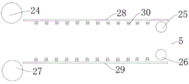
fig. 3 is a schematic structural view of a color fixing component of a bidirectional dyeing device for clothing production;
fig. 4 is a schematic structural diagram of a first two-way dyeing equipment tentering assembly for clothing production.
Wherein, 1, a dyeing cabin, 2, a feed inlet, 3, a dyeing component, 4, a first cloth guide roller, 5, a color fixing component, 6, a second cloth guide roller, 7, a tentering component, 8, a drying component, 9, an electric winding shaft, 10, a winding shaft support frame, 11, a dye liquor recovery component, 12, a dye tank, 13, a spray head, 14, a conveying pipeline, 15, a discharge faucet, 16, a fixed frame, 17, a dyeing compression roller, 18, a screw rod, 19, a fastening nut, 20, a connecting support, 21, a liquid storage box, 22, a dye liquor collection part, 23, a collection pipeline, 24, a first color fixing cloth guide roller, 25, a second color fixing cloth guide roller, 26, a third color fixing cloth guide roller, 27, a fourth color fixing cloth guide roller, 28, a first ultrasonic transducer generator baffle, 29, a second ultrasonic transducer generator baffle, 30, an ultrasonic transducer generator, 31, a driving rotating shaft, 32, a driven rotating shaft, 33 and a first driving belt, 34. the device comprises a second transmission belt 35, a first tentering assembly 35, a second tentering assembly 37, iron blocks 38, a drying baffle fixing support 39, a dryer 40, an air conveying pipe 41, a baffle 42, a diversion pipeline 43 and magnet blocks.
Detailed Description
The present invention will be described in further detail with reference to the accompanying drawings.
As shown in figures 1-4, the utility model relates to a bidirectional dyeing equipment for clothing production, which comprises a dyeing cabin 1, a feed inlet 2, a dyeing component 3, a first cloth guide roller 4, a color fixing component 5, a second cloth guide roller 6, a stentering component 7, a drying component 8, an electric winding shaft 9, a winding shaft support frame 10 and a dye liquor recovery component 11, wherein the dyeing cabin 1 is arranged in a hollow cavity structure, the feed inlet 2 is arranged at the upper end of the dyeing cabin 1 and is communicated with the cavity of the dyeing cabin 1, the dyeing component 3 is arranged on the dyeing cabin 1 and is close to the feed inlet 2, one end of the dye liquor recovery component 11 is arranged on the dyeing cabin 1, the other end of the dye liquor recovery component 11 is arranged on the dyeing component 3, the first cloth guide roller 4 is arranged on two opposite side walls of the dyeing cabin 1 and is arranged below the dye liquor recovery component 11, the second cloth guide roller 6 is arranged on two opposite side walls of the dyeing cabin 1 and is arranged below the first cloth guide roller 4, fixing subassembly 5 is located in dyeing storehouse 1 and locates between first fabric guide roll 4 and the second fabric guide roll 6, winding shaft support frame 10 is located in dyeing storehouse 1, electronic winding shaft 9 is rotatable to be located on the winding shaft support, tentering subassembly 7 is located in dyeing storehouse 1 and is located between electronic winding shaft 9 and the second fabric guide roll 6, drying subassembly 8 is located and is tentered subassembly 7 both sides.
The printing and dyeing component 3 comprises a dyeing tank 12, a spray head 13, a conveying pipeline 14, a discharge tap 15, a fixing frame 16, a printing and dyeing compression roller 17, a screw rod 18, a fastening nut 19 and a connecting support 20, wherein the dyeing tank 12 is arranged on the outer wall of a dyeing bin 1 and is close to a feed inlet 2, the spray head 13 is arranged at the bottom of the dyeing tank 12 and is arranged on the side wall of the dyeing bin 1 in a penetrating way, the spray head 13 is arranged at the bottom of the dyeing bin 1 in a penetrating way and is communicated with the dye tank 12 in a penetrating way, one end of the conveying pipeline 14 is arranged at the bottom of the dyeing tank 12, the other end of the conveying pipeline 14 is arranged on the side wall of the dyeing bin 1, the discharge tap 15 is arranged on the side wall of the dyeing bin 1 and is communicated with the conveying pipeline 14, the fixing frame 16 is arranged on the inner wall of the dyeing bin 1, the, the surface of the screw rod 18 is provided with threads, the printing and dyeing compression roller 17 is rotatably arranged on the connecting support 20, the fastening nut 19 is arranged on the screw rod 18 and is positioned outside the dyeing bin 1, the threads are arranged in the fastening nut 19, the fastening nut 19 is in threaded engagement with the screw rod 18, and the printing and dyeing components 3 are symmetrically arranged along the axis of the dyeing bin 1.
The dye liquor recovery assembly 11 comprises a dye liquor storage box 21, a dye liquor collection part 22 and a collection pipeline 23, wherein the dye liquor storage box 21 is arranged on the outer side wall of the dyeing bin 1, the collection pipeline 23 penetrates through the side wall of the dyeing bin 1 and is arranged on the dye liquor storage box 21 and communicated with the dye liquor storage box 21, one end of the dye liquor collection part 22 is arranged on the collection pipeline 23, the other end of the dye liquor collection part 22 is arranged on the connecting support 20, the collection pipeline 23 is in a telescopic elastic pipeline structure, the dye liquor recovery assembly 11 is symmetrically arranged by the axis of the dyeing bin 1, and the distance between the printing and dyeing compression rollers 17 on the symmetrically arranged dye liquor recovery assembly 11 is larger than the distance between the dye liquor collection parts 22 on the symmetrically arranged dye liquor recovery assembly 11.
The dye liquor collecting piece 22 is arranged in a U-shaped structure with one open end, the opening direction of the dye liquor collecting piece 22 is opposite to the printing and dyeing press roller 17, the dye liquor collecting piece 22 is arranged in an inclined mode, and the height of one end, close to the printing and dyeing press roller 17, of the dye liquor collecting piece 22 is higher than that of one end, close to the liquor storage box 21, of the dye liquor collecting piece 22.
The first cloth guide roller 4 is arranged below the dye liquor collecting piece 22 and close to one printing and dyeing press roller 17 of the two symmetrical printing and dyeing press rollers 17, and the horizontal distance between the roller surface of the first cloth guide roller 4 and the roller surface of the other printing and dyeing press roller 17 is equal to the horizontal distance between the roller surfaces of the two symmetrical printing and dyeing press rollers 17.
The color fixing component 5 comprises a first color fixing cloth guide roller 24, a second color fixing cloth guide roller 25, a third color fixing cloth guide roller 26, a fourth color fixing cloth guide roller 27, a first ultrasonic transduction generator baffle 28, a second ultrasonic transduction generator baffle 29 and a second ultrasonic transduction generator 30, one side of the first ultrasonic transduction generator baffle 28 is arranged on the inner side wall of the dyeing bin 1 and below the first cloth guide roller 4, one side of the second ultrasonic transduction generator baffle 29 is arranged on the inner side wall of the dyeing bin 1 and below the first ultrasonic transduction generator baffle 28, the second ultrasonic transduction generator baffle 29 and the side wall of the dyeing bin 1 form a cavity with an opening on one side, the ultrasonic transduction generator 30 is uniformly arranged on the inner wall of the dyeing bin 1 at intervals and is arranged on the inner side wall of the first ultrasonic transduction generator baffle 28 and the second ultrasonic transduction generator baffle 29, the interval between ultrasonic transduction generator 30 and ultrasonic transduction generator baffle 28 and the two 29 ultrasonic transduction generator baffles is greater than the thickness of cloth, ultrasonic transduction generator 30 evenly is equipped with a plurality of groups, fixation fabric guide roller 24 and fixation fabric guide roller two 25 are located on dyeing storehouse 1 inner wall and locate the both ends of ultrasonic transduction generator baffle 28 respectively, fixation fabric guide roller two 25 is located the below of ultrasonic transduction generator baffle 28, the interval between fixation fabric guide roller two 25 and ultrasonic transduction generator baffle 28 and dyeing storehouse 1 wall all is greater than the thickness of cloth, fixation fabric guide roller four 27 and fixation fabric guide roller three 26 are located on dyeing storehouse 1 inner wall and locate the both ends of ultrasonic transduction generator baffle 28 respectively, fixation fabric guide roller three 26 is located the top of ultrasonic transduction generator baffle two 29, the interval between three 26 of fixation fabric guide roller and two 29 and the 1 walls in dyeing storehouse of ultrasonic wave transduction generator baffle all is greater than the thickness of cloth, the below of fixation fabric guide roller two 25 is located to three 26 of fixation fabric guide roller, the horizontal interval between fixation fabric guide roller 24 and the first fabric guide roller 4 is greater than the horizontal interval between the expansion end of ultrasonic wave transduction generator baffle 28 and the first fabric guide roller 4, the below of fixation fabric guide roller 24 is located to fixation fabric guide roller four 27, the vertical distance between fixation fabric guide roller 24 and the fixation fabric guide roller four 27 is greater than the vertical distance between ultrasonic wave transduction generator baffle 28 alive and ultrasonic wave transducer generator baffle two 29.
The magnet blocks 43 are arranged on the first transmission belt 33 and the second transmission belt 34 in the first tentering assembly 35 at uniform intervals, the iron blocks 37 are arranged on the first transmission belt 33 and the second transmission belt 34 in the second tentering assembly 36 at uniform intervals, and the magnet blocks 43 and the iron blocks 37 are arranged in the same number and in one-to-one correspondence.
When the dyeing machine is used, the fastening nut 19 is taken down, the connecting support 20 is driven by the movable screw 18 to slide back and forth in the fixing frame 16 to adjust the distance between the printing and dyeing press rollers 17, the movable screw 18 is stopped after the connecting support 20 drives the symmetrically arranged printing and dyeing press rollers 17 to move to a proper distance, the fastening nut 19 is screwed to fix the position of the screw 18, cloth enters the dyeing bin 1 through the feed inlet 2, dye in the dye tank 12 firstly sprays dye on the cloth through the spray nozzle 13 for the first time, meanwhile, the dye in the dye tank 12 enters the discharge tap 15 through the conveying pipeline 14, the dye flowing out of the discharge tap 15 falls onto the printing and dyeing press rollers 17, the two symmetrical printing and dyeing press rollers 17 perform two-way extrusion dyeing on the cloth, simultaneously, the dye is uniformly distributed on the cloth surface in the extrusion process, redundant dye on the printing and dyeing roll drips onto the dye collecting piece 22 below, the dye is collected on the dye collecting piece 22 and enters the liquid storage tank 21 through the collecting pipeline 23, the cloth after printing and dyeing treatment sequentially enters a cavity with one side opening formed by a first cloth guide roller 4 and a first color fixing cloth guide roller 24, the cavity is formed by a first ultrasonic energy conversion generator baffle plate 28, a second ultrasonic energy conversion generator baffle plate 29 and the side wall of a dyeing bin 1, the cloth firstly passes through a gap between an ultrasonic energy conversion generator 30 and the first ultrasonic energy conversion generator baffle plate 28, then enters a space between a first tentering component 35 and a second tentering component 36 which are symmetrically arranged through a second color fixing cloth guide roller 25, a third color fixing cloth guide roller 26, a gap between the ultrasonic energy conversion generator 30 and the second ultrasonic energy conversion generator baffle plate 29, a fourth color fixing cloth guide roller 27 and a second cloth guide roller 6, a first driving belt 33 in the first tentering component 35 and a second tentering component 36 are mutually adsorbed by a magnet block 37 on the second driving belt 34 and a magnet block 38 on the first driving belt 33 in the second tentering component 36 through force, so that two sides of the cloth are clamped and fixed between the magnet block 37, the cloth is tentered and fixed, then the first transmission belt 33 and the second transmission belt 34 on the first tentering assembly 35 and the second tentering assembly 36 rotate in the same direction with the moving direction of the cloth, the cloth is clamped from two sides and enters the drying assembly 8, hot air generated by the dryer 39 is uniformly sprayed onto the cloth surface through the air conveying pipe 40 and the diversion pipeline 42, moisture on the cloth is taken away by the hot air, the cloth is dried quickly, and the dried cloth is wound onto the electric winding roller 9 along with the rotation of the electric winding roller 9.
The present invention and the embodiments thereof have been described above, but the description is not limited thereto, and the embodiment shown in the drawings is only one of the embodiments of the present invention, and the actual structure is not limited thereto. In summary, those skilled in the art should understand that they should not be limited to the embodiments described above, and that they can design the similar structure and embodiments without departing from the spirit of the invention.
Claims (9)
1. The utility model provides a bidirectional dyeing equipment for clothing production which characterized in that: the dyeing device comprises a dyeing bin, a feed inlet, a dyeing component, a first cloth guide roller, a color fixing component, a second cloth guide roller, a tentering component, a drying component, an electric winding shaft, a winding shaft support frame and a dye liquor recovery component, wherein the dyeing bin is of a hollow cavity structure, the feed inlet is arranged at the upper end of the dyeing bin and is communicated with the hollow cavity of the dyeing bin, the dyeing component is arranged on the dyeing bin and is close to the feed inlet, one end of the dye liquor recovery component is arranged on the dyeing bin, the other end of the dye liquor recovery component is arranged on the dyeing component, the first cloth guide roller is arranged on two opposite side walls of the dyeing bin and is arranged below the dye liquor recovery component, the second cloth guide roller is arranged on two opposite side walls of the dyeing bin and is arranged below the first cloth guide roller, the color fixing component is arranged in the dyeing bin and is arranged between the first cloth guide roller and the second cloth guide roller, the winding shaft support is erected in the dyeing, the electric winding shaft is rotatably arranged on the winding shaft support, the tentering assembly is arranged in the dyeing bin and is arranged between the electric winding shaft and the second cloth guide roller, the drying assembly is arranged in the dyeing bin and is arranged between the electric winding shaft and the second cloth guide roller, and the drying assembly is arranged on two sides of the tentering assembly.
2. The bi-directional dyeing equipment for garment production according to claim 1, characterized in that: the printing and dyeing component comprises a printing and dyeing tank, a spray head, a conveying pipeline, a discharge tap, a fixing frame, a printing and dyeing compression roller, a screw, a fastening nut and a connecting bracket, the dye pot is arranged on the outer wall of the dyeing bin and close to the feed inlet, the spray head penetrates through the side wall of the dyeing bin and is arranged at the bottom of the dye pot and communicated with the dye pot, one end of the conveying pipeline is arranged at the bottom of the dyeing tank, the other end of the conveying pipeline is arranged on the side wall of the dyeing bin, the discharge tap penetrates through the side wall of the dyeing bin and is communicated with the conveying pipeline, the fixing frame is arranged on the inner wall of the dyeing bin, the connecting bracket can be arranged in the fixing bracket in a sliding way, the screw rod sequentially penetrates through the fixing bracket on the side wall of the dyeing bin and is arranged on the connecting bracket, the printing and dyeing compression roller is rotatably arranged on the connecting support, the fastening nut is arranged on the screw rod and is positioned outside the dyeing bin, and the printing and dyeing components are symmetrically arranged along the axis of the dyeing bin.
3. The bi-directional dyeing equipment for garment production according to claim 1, characterized in that: the dye liquor recovery assembly comprises a dye liquor storage box, a dye liquor collection part and a collection pipeline, wherein the dye liquor storage box is arranged on the outer side wall of the dyeing bin, the collection pipeline penetrates through the side wall of the dyeing bin and is arranged on the dye liquor storage box and communicated with the dye liquor storage box, one end of the dye liquor collection part is arranged on the collection pipeline, the other end of the dye liquor collection part is arranged on the connecting support, the collection pipeline is of a telescopic elastic pipeline structure, the dye liquor recovery assembly is symmetrically arranged by the axis of the dyeing bin, and the distance between printing and dyeing compression rollers on the symmetrically arranged dye liquor recovery assembly is larger than the distance between the dye liquor collection parts on the symmetrically arranged dye liquor recovery assembly.
4. The bi-directional dyeing equipment for garment production according to claim 3, characterized in that: the dye liquor collecting piece is arranged in a U-shaped structure with an opening at one end, the opening direction of the dye liquor collecting piece is opposite to the printing and dyeing compression roller, the dye liquor collecting piece is arranged obliquely, and the height of one end, close to the printing and dyeing compression roller, of the dye liquor collecting piece is higher than that of one end, close to the liquor storage box, of the dye liquor collecting piece.
5. The bi-directional dyeing equipment for garment production according to claim 1, characterized in that: the first cloth guide roller is arranged below the dye liquor collecting piece and close to one of the two symmetrical printing and dyeing press rollers, and the horizontal distance between the roller surface of the first cloth guide roller and the roller surface of the other printing and dyeing press roller is equal to the horizontal distance between the roller surfaces of the two symmetrical printing and dyeing press rollers.
6. The bi-directional dyeing equipment for garment production according to claim 1, characterized in that: the fixation subassembly includes fixation fabric guide roller one, fixation fabric guide roller two, fixation fabric guide roller three, fixation fabric guide roller four, ultrasonic transduction generator baffle one, ultrasonic transduction generator baffle two and ultrasonic transduction generator, the below of just locating first fabric guide roller on the dyeing storehouse inside wall is located to ultrasonic transduction generator baffle one side, two one sides of ultrasonic transduction generator baffle are located on the dyeing storehouse inside wall and are located the below of ultrasonic transduction generator baffle one, ultrasonic transduction generator baffle two constitute one side open-ended cavity with the lateral wall in dyeing storehouse, ultrasonic transduction generator uniform separation locates on the dyeing storehouse inner wall and locates ultrasonic transduction generator baffle one and two opposite medial surfaces of ultrasonic transduction generator baffle, the interval between ultrasonic transduction generator and ultrasonic transduction generator baffle one and the ultrasonic transduction generator baffle two is greater than the thickness of cloth The ultrasonic wave transduction generator evenly is equipped with a plurality of groups, first fixation fabric guide roller and second fixation fabric guide roller are located on the dyeing storehouse inner wall and locate the both ends of first ultrasonic wave transduction generator baffle respectively, second fixation fabric guide roller is located the below of first ultrasonic wave transduction generator baffle, second fixation fabric guide roller and first ultrasonic wave transduction generator baffle and the thickness that the interval between the dyeing storehouse wall all is greater than the cloth, fourth fixation fabric guide roller and third fixation fabric guide roller are located on the dyeing storehouse inner wall and locate the both ends of first ultrasonic wave transduction generator baffle respectively, third fixation fabric guide roller is located the top of second ultrasonic wave transduction generator baffle, third fixation fabric guide roller and the interval between second ultrasonic wave transduction generator baffle and the dyeing storehouse wall all are greater than the thickness of cloth, third fixation fabric guide roller is located the below of second fixation fabric guide roller, the horizontal interval between first fixation fabric guide roller and the first fabric guide roller is greater than the live of first ultrasonic wave transduction generator baffle Move the horizontal distance between end and the first fabric guide roll, the below of fixation fabric guide roll one is located to fixation fabric guide roll four, the vertical distance between fixation fabric guide roll one and the fixation fabric guide roll four is greater than the vertical distance between ultrasonic wave transduction generator baffle one and ultrasonic wave transduction generator baffle two.
7. The bi-directional dyeing equipment for garment production according to claim 1, characterized in that: the tentering component includes initiative axis of rotation, driven axis of rotation, drive belt one and drive belt two, initiative axis of rotation and driven axis of rotation are rotatable establish with dyeing storehouse on the inner wall, the top of stoving subassembly is located to the initiative axis of rotation, the below of stoving subassembly is located to driven axis of rotation, initiative axis of rotation and driven axis of rotation one end are located to drive belt one around connecing, drive belt two around connecing locate initiative axis of rotation and driven axis of rotation other end, drive belt one and the width that the interval between the drive belt two is less than the cloth, the tentering component is equipped with two sets ofly, two sets ofly are tentering component one and tentering component two respectively, tentering component one and tentering component two use dyeing storehouse axis to set up as.
8. The bi-directional dyeing equipment for garment production according to claim 7, characterized in that: the tentering component is characterized in that magnet blocks are arranged on the first transmission belt and the second transmission belt at uniform intervals, iron blocks are arranged on the first transmission belt and the second transmission belt at uniform intervals, and the magnet blocks and the iron blocks are arranged in an equal number in a one-to-one correspondence mode.
9. The bi-directional dyeing equipment for garment production according to claim 7, characterized in that: the stoving subassembly is including stoving baffle fixed bolster, drying-machine, defeated tuber pipe, baffle and reposition of redundant personnel pipeline, stoving baffle fixed bolster is located on the lateral wall in dyeing storehouse, the baffle is located on the stoving baffle fixed bolster, the drying-machine is located on the baffle and is close to dyeing storehouse lateral wall, defeated tuber pipe is located on the baffle and is connected with the output of drying-machine, the reposition of redundant personnel pipeline is located on the baffle, the reposition of redundant personnel pipeline is located defeated tuber pipe and is kept away from the one end of dyeing storehouse lateral wall and communicate with defeated tuber pipe, the stoving subassembly uses dyeing storehouse axis as the axial symmetry setting.
Priority Applications (1)
| Application Number | Priority Date | Filing Date | Title |
|---|---|---|---|
| CN201921848652.5U CN211921939U (en) | 2019-10-30 | 2019-10-30 | Bidirectional dyeing equipment for clothing production |
Applications Claiming Priority (1)
| Application Number | Priority Date | Filing Date | Title |
|---|---|---|---|
| CN201921848652.5U CN211921939U (en) | 2019-10-30 | 2019-10-30 | Bidirectional dyeing equipment for clothing production |
Publications (1)
| Publication Number | Publication Date |
|---|---|
| CN211921939U true CN211921939U (en) | 2020-11-13 |
Family
ID=73318815
Family Applications (1)
| Application Number | Title | Priority Date | Filing Date |
|---|---|---|---|
| CN201921848652.5U Active CN211921939U (en) | 2019-10-30 | 2019-10-30 | Bidirectional dyeing equipment for clothing production |
Country Status (1)
| Country | Link |
|---|---|
| CN (1) | CN211921939U (en) |
-
2019
- 2019-10-30 CN CN201921848652.5U patent/CN211921939U/en active Active
Similar Documents
| Publication | Publication Date | Title |
|---|---|---|
| CN107974786B (en) | Printing and dyeing equipment | |
| CN209276799U (en) | A kind of purified cotton high grade mercerising reeled yarn short route pretreating device | |
| CN107938228A (en) | Cloth printing and dyeing drying integrated device | |
| CN111637697A (en) | A drum-type drying system for textile fabric production | |
| CN108950966A (en) | A kind of cloth ironing apparatus | |
| CN208751219U (en) | A kind of weaving automatic drier convenient for adjusting | |
| CN114250568B (en) | Cloth rapid ironing device for clothing production | |
| CN215490857U (en) | Drying treatment device for improving comprehensive yarn dewatering efficiency | |
| CN206616359U (en) | A kind of spiral dyeing apparatus of eyelet fabric | |
| CN211921939U (en) | Bidirectional dyeing equipment for clothing production | |
| CN205975038U (en) | Cloth gripper tent stabilisation groove of straight roller cloth gripper knitting mercerizing range of intelligence resolving dampness cloth hot alkaline | |
| CN220099432U (en) | Double-sided dyeing device for fabric | |
| CN210886553U (en) | Dyeing apparatus is used in fabrics processing | |
| CN112647228A (en) | Double-sided drying equipment for production and processing of polyester fabric | |
| CN210456757U (en) | Winding device for printing and dyeing | |
| CN209975162U (en) | Ironing device for garment production | |
| CN111780492A (en) | Adjustable water squeezing device for textile carpet | |
| CN216156161U (en) | Non-woven fabrics processing is with dyeing apparatus who has stoving function | |
| CN214529666U (en) | High-fastness dyeing equipment for elastic cloth | |
| CN113652792A (en) | Water spraying textile machine | |
| CN106120217B (en) | A kind of energy-efficient loose formula rope form washing process and device | |
| CN215163765U (en) | Washing unit modularization box structure | |
| CN211142466U (en) | Water-saving and environment-friendly washing and scouring machine | |
| CN108893905A (en) | A kind of printing and dyeing fabrics efficient water-removing device | |
| CN211546977U (en) | Clothing cloth flattening ironing device |
Legal Events
| Date | Code | Title | Description |
|---|---|---|---|
| GR01 | Patent grant | ||
| GR01 | Patent grant |