CN211895809U - Spacing buffer gear of flexible arm board - Google Patents
Spacing buffer gear of flexible arm board Download PDFInfo
- Publication number
- CN211895809U CN211895809U CN201922183910.9U CN201922183910U CN211895809U CN 211895809 U CN211895809 U CN 211895809U CN 201922183910 U CN201922183910 U CN 201922183910U CN 211895809 U CN211895809 U CN 211895809U
- Authority
- CN
- China
- Prior art keywords
- telescopic
- telescopic arm
- fixed
- arm
- flexible arm
- Prior art date
- Legal status (The legal status is an assumption and is not a legal conclusion. Google has not performed a legal analysis and makes no representation as to the accuracy of the status listed.)
- Active
Links
Images


Abstract
The utility model discloses a spacing buffer gear of flexible arm armplate, including fixed flexible arm, the flexible arm of activity, buffer structure and extending structure, the inside flexible arm of activity that is equipped with of fixed flexible arm, the inside both sides that are located the flexible arm of activity and stretch out one end of fixed flexible arm have all welded buffer structure, buffer structure comprises telescopic link, sleeve and spring, the inside upper and lower both sides that are close to the flexible arm of activity and stretch out one end of fixed flexible arm all are equipped with position sensor, position sensor one side all is equipped with electric valve, it all is equipped with fixed frame to lie in the electric valve outside on the fixed flexible arm, the inside middle part of fixed frame is equipped with extending structure, the extending structure other end is equipped with spacing frame. The buffering and limiting structure of the utility model complements each other, avoids the damage of overlarge impact force under single action, prolongs the service life of the utility model, and does not need to be replaced frequently; the telescopic arm can buffer when extending out and retracting, and the protection is more perfect.
Description
Technical Field
The utility model relates to a flexible arm buffering technical field especially relates to a spacing buffer gear of flexible arm board.
Background
According to the current situation of the existing crane lifting appliance, when the telescopic arm of the crane lifting appliance stretches to the end position, large impact can be generated due to the inertia of the telescopic arm.
One method for realizing buffering of the telescopic arm buffering device in the current market is to increase a buffering pad or a limiting block on a basic beam to reduce the impact in the stretching process of a lifting appliance, and the method can play a certain buffering role, but the buffering pad and the limiting block are easy to damage due to long-term impact bearing, and certain manpower and material resources are consumed for replacement; the other mode is that when the telescopic beam of the lifting appliance extends to the extreme position, the damping oil cylinder additionally arranged on the basic beam is used for realizing the buffering, and the method can only realize the buffering when the lifting appliance extends and cannot relieve the impact between the telescopic beam and the basic beam when the lifting appliance retracts.
An effective solution to the problems in the related art has not been proposed yet.
SUMMERY OF THE UTILITY MODEL
The utility model aims at solving the defects existing in the prior art and providing a spacing buffer mechanism of a telescopic boom arm plate.
In order to achieve the above purpose, the utility model adopts the following technical scheme:
a telescopic arm plate limiting and buffering mechanism comprises a fixed telescopic arm, a movable telescopic arm, a buffering structure and a telescopic structure, wherein the movable telescopic arm is arranged inside the fixed telescopic arm, the movable telescopic arm is sleeved with the fixed telescopic arm, the buffering structure is welded on two sides of the extending end of the movable telescopic arm inside the fixed telescopic arm, the buffering structure consists of a telescopic rod, a sleeve and a spring, position sensors are arranged on the upper side and the lower side of the extending end of the movable telescopic arm inside the fixed telescopic arm, an electric valve is arranged on one side of each position sensor, a fixing frame is arranged on the fixed telescopic arm and positioned outside the electric valve, the outer walls of the fixing frame and the fixed telescopic arm are welded and connected, the telescopic structure is arranged in the middle of the inside of the fixing frame, a limiting frame is arranged on the other end of the telescopic structure, and the same pull rod is welded, the pull rod runs through the fixed frame, and the pull rod is connected with the fixed frame in a sliding mode.
Preferably, buffer structure's sleeve and fixed flexible arm inner wall welded connection, the inside telescopic link that is equipped with of sleeve, telescopic link and sleeve cup joint, sleeve both sides inner wall all is equipped with the spout, telescopic link bottom both sides welding has the slider, the slider is located inside the spout, just slider and spout sliding connection.
Preferably, the bottom of the telescopic rod is provided with a spring, one end of the spring is connected with the bottom of the telescopic rod in a welding mode, and the other end of the spring is connected with the bottom of the sleeve in a welding mode.
Preferably, the maximum distance that the position sensor can sense is equal to the distance between the position sensor and the electrically operated valve.
Preferably, the two sides of the tail end of the movable telescopic arm are both welded with a convex block, and the width of the convex block is 3-5cm smaller than that of the limiting frame.
Preferably, extending structure and buffer structure are the same, extending structure's sleeve and fixed frame inner wall welded connection, extending structure's telescopic link and spacing frame welded connection.
Preferably, the upper side and the lower side of the inner part of the fixed telescopic arm, which are far away from the extending end of the movable telescopic arm, are provided with a position sensor, an electric valve, a limiting frame, a fixing frame, a telescopic structure and a pull rod which have the same position relation.
The utility model has the advantages that:
1. the utility model discloses a set up buffer structure and effectively cushion the impact force of flexible arm of activity, position sensor senses being close to of lug after the lug compresses one section distance with the telescopic link to the sleeve in, open signal transmission to control system real time control electric valve, thereby the extending structure returns to normal condition after lacking pressure and makes spacing frame block the lug, the completion is spacing to the flexible arm of activity, buffer structure and limit structure complement each other, impact force damages buffer structure and limit structure excessively under avoiding the single action, prolong its life, need not frequent change, the material resources of using manpower sparingly.
2. The utility model discloses both ends at fixed flexible arm have all set up buffer structure and limit structure, and the flexible arm of activity all can reach the buffering effect when stretching out and retracting, and is more perfect to the protection of flexible arm.
Drawings
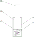
Fig. 1 is a schematic structural view of a telescopic boom arm plate limiting and buffering mechanism provided by the present invention;
fig. 2 is a schematic diagram of buffering and limiting when the telescopic arm of the telescopic arm plate limiting and buffering mechanism provided by the utility model extends out;
fig. 3 is a schematic view of a buffer structure or a telescopic structure of a telescopic boom arm plate limiting buffer mechanism provided by the present invention;
fig. 4 is the utility model provides a spacing buffer gear's of flexible armplate A department enlargedly.
In the figure: 1. a movable telescopic arm; 2. a buffer structure; 3. a position sensor; 4. a pull rod; 5. a fixing frame; 6. fixing a telescopic arm; 7. a limiting frame; 8. an electrically operated valve; 9. a bump; 10. a telescopic rod; 11. a sleeve; 12. a slider; 13. a spring; 14. a chute; 15. a telescopic structure.
Detailed Description
The technical solutions in the embodiments of the present invention will be described clearly and completely with reference to the accompanying drawings in the embodiments of the present invention, and it is obvious that the described embodiments are only some embodiments of the present invention, not all embodiments.
Referring to fig. 1-4, a telescopic arm plate limiting and buffering mechanism comprises a fixed telescopic arm 6, a movable telescopic arm 1, a buffering structure 2 and a telescopic structure 15, wherein the fixed telescopic arm 6 is internally provided with the movable telescopic arm 1, the movable telescopic arm 1 is sleeved with the fixed telescopic arm 6, the buffering structure 2 is welded on two sides of the fixed telescopic arm 6, which are positioned at the extending end of the movable telescopic arm 1, the buffering structure 2 consists of a telescopic rod 10, a sleeve 11 and a spring 13, the upper side and the lower side of the fixed telescopic arm 6, which are close to the extending end of the movable telescopic arm 1, are respectively provided with a position sensor 3, one side of the position sensor 3 is provided with an electric valve 8, the electric valve 8 applies pressure to the telescopic rod 10 of the telescopic structure 15, the fixed telescopic arm 6 is provided with a fixed frame 5 outside the electric valve 8, the outer walls of the fixed frame 5 and the fixed telescopic arm 6 are, the other end of the telescopic structure 15 is provided with a limiting frame 7, two ends of the outer side of the limiting frame 7 are welded with the same pull rod 4, the pull rod 4 penetrates through the fixed frame 5, the pull rod 4 is connected with the fixed frame 5 in a sliding mode, and the limiting frame 7 can be pulled back by the pull rod 4.
The utility model discloses in, buffer structure 2's sleeve 11 and the 6 inner wall welded connections of fixed flexible arm, sleeve 11 inside is equipped with telescopic link 10, and telescopic link 10 and sleeve 11 cup joint, and sleeve 11 both sides inner wall all is equipped with spout 14, and the welding of telescopic link 10 bottom both sides has slider 12, and inside slider 12 is located spout 14, and slider 12 and the 14 sliding connections of spout. The bottom of the telescopic rod 10 is provided with a spring 13, one end of the spring 13 is connected with the bottom of the telescopic rod 10 in a welding mode, and the other end of the spring 13 is connected with the bottom of the inner portion of the sleeve 11 in a welding mode. The maximum distance that the position sensor 3 can sense is equal to the distance between the position sensor 3 and the electric valve 8, and when the bump 9 reaches the position under the electric valve 8, the position sensor 3 senses the bump. The two sides of the tail end of the movable telescopic arm 1 are respectively welded with a convex block 9, the width of each convex block 9 is 3-5cm smaller than that of the limiting frame 7, and the limiting frame 7 can clamp the position of each convex block 9. The telescopic structure 15 is the same as the buffer structure 2 in structure, the sleeve 11 of the telescopic structure 15 is connected with the inner wall of the fixed frame 5 in a welding manner, and the telescopic rod 10 of the telescopic structure 15 is connected with the limiting frame 7 in a welding manner. The upper side and the lower side of the inside of the fixed telescopic arm 6, which are far away from the extending end of the movable telescopic arm 1, are provided with the position sensor 3, the electric valve 8, the limiting frame 7, the fixed frame 5, the telescopic structure 15 and the pull rod 4 which have the same position relation, and the impact force generated when the movable telescopic arm 1 retracts can be buffered and limited.
The working principle is as follows: when the movable telescopic arm 1 extends or retracts, the convex block 9 extrudes the telescopic rod 10, the telescopic rod 10 slides towards the sleeve 11, thereby extruding the spring 13, the spring 13 generates a force in the direction opposite to the pressure to buffer the impact force of the movable telescopic arm 1, when the convex block 9 compresses the telescopic rod 10 towards the sleeve 11 for a certain distance until the convex block 9 is positioned under the electric valve 8, the position sensor 3 senses the approach of the convex block 9, sends a signal to the control system to control the electric valve 8 to open in real time, the spring 13 drives the telescopic rod 10 to return to a normal state after the telescopic rod 10 of the telescopic structure 15 lacks the pressure, so that the limiting frame 7 clamps the convex block 9, the limiting of the movable telescopic arm 1 is completed, the buffer structure 2 and the limiting structure are supplemented, the buffer structure 2 and the limiting structure are prevented from being damaged due to overlarge impact force under the single action, the service life of the buffer structure is, manpower and material resources are saved; after the buffering and limiting, the pull rod 4 can be pulled manually to pull the limiting frame 7 back and then close the electric valve 8.
Having shown and described the basic principles and essential features of the invention and advantages thereof, it will be apparent to those skilled in the art that the invention is not limited to the details of the foregoing exemplary embodiments, but is capable of other specific forms without departing from the spirit or essential characteristics thereof, and it is therefore intended that the embodiments be considered as exemplary and not limiting in any way, since the scope of the invention is defined by the appended claims rather than by the foregoing description, and all changes which come within the meaning and range of equivalency of the claims are therefore intended to be embraced therein and are therefore not to be embraced therein by any reference numerals in the claims.
Furthermore, it should be understood that although the present description refers to embodiments, not every embodiment may contain only a single embodiment, and such description is for clarity only, and those skilled in the art should integrate the description, and the embodiments may be combined as appropriate to form other embodiments understood by those skilled in the art.
Claims (7)
1. A telescopic arm plate limiting and buffering mechanism comprises a fixed telescopic arm (6), a movable telescopic arm (1), a buffering structure (2) and a telescopic structure (15), and is characterized in that the movable telescopic arm (1) is arranged inside the fixed telescopic arm (6), the movable telescopic arm (1) and the fixed telescopic arm (6) are sleeved, the buffering structure (2) is welded on two sides of one end, extending out from the movable telescopic arm (1), inside the fixed telescopic arm (6), of the fixed telescopic arm (6), the buffering structure (2) is composed of a telescopic rod (10), a sleeve (11) and a spring (13), position sensors (3) are arranged on the upper side and the lower side, close to one end, extending out from the movable telescopic arm (1), of the fixed telescopic arm (6), electric valves (8) are arranged on one side of the position sensors (3), and fixed frames (5) are arranged on the outer sides of the electric valves (8), fixed frame (5) and fixed telescopic arm (6) outer wall welded connection, the inside middle part of fixed frame (5) is equipped with extending structure (15), the extending structure (15) other end is equipped with spacing frame (7), the welding of spacing frame (7) outside both ends has same pull rod (4), pull rod (4) run through fixed frame (5), just pull rod (4) and fixed frame (5) sliding connection.
2. The limiting and buffering mechanism for the telescopic arm plate according to claim 1, wherein a sleeve (11) of the buffering structure (2) is connected with the inner wall of the fixed telescopic arm (6) in a welding manner, a telescopic rod (10) is arranged inside the sleeve (11), the telescopic rod (10) is connected with the sleeve (11) in a sleeving manner, sliding grooves (14) are formed in the inner walls of two sides of the sleeve (11), sliding blocks (12) are welded on two sides of the bottom of the telescopic rod (10), the sliding blocks (12) are located inside the sliding grooves (14), and the sliding blocks (12) are connected with the sliding grooves (14) in a sliding manner.
3. The telescopic arm plate limiting and buffering mechanism is characterized in that a spring (13) is arranged at the bottom of the telescopic rod (10), one end of the spring (13) is connected with the bottom of the telescopic rod (10) in a welding mode, and the other end of the spring (13) is connected with the bottom of the inner portion of the sleeve (11) in a welding mode.
4. A telescopic boom arm plate limit buffer mechanism according to claim 1, characterized in that the maximum distance which the position sensor (3) can sense is equal to the distance between the position sensor (3) and the electric valve (8).
5. The limiting and buffering mechanism of the telescopic arm plate as claimed in claim 1, wherein the two sides of the tail end of the movable telescopic arm (1) are welded with lugs (9), and the width of the lugs (9) is 3-5cm smaller than that of the limiting frame (7).
6. The telescopic boom arm plate limiting and buffering mechanism is characterized in that the telescopic structure (15) and the buffering structure (2) are identical in structure, a sleeve (11) of the telescopic structure (15) is connected with the inner wall of the fixed frame (5) in a welding mode, and a telescopic rod (10) of the telescopic structure (15) is connected with the limiting frame (7) in a welding mode.
7. The telescopic arm plate limiting and buffering mechanism is characterized in that a position sensor (3), an electric valve (8), a limiting frame (7), a fixed frame (5), a telescopic structure (15) and a pull rod (4) which are in the same position relation are arranged on the upper side and the lower side of the inner part of the fixed telescopic arm (6), which are far away from the extending end of the movable telescopic arm (1).
Priority Applications (1)
| Application Number | Priority Date | Filing Date | Title |
|---|---|---|---|
| CN201922183910.9U CN211895809U (en) | 2019-12-09 | 2019-12-09 | Spacing buffer gear of flexible arm board |
Applications Claiming Priority (1)
| Application Number | Priority Date | Filing Date | Title |
|---|---|---|---|
| CN201922183910.9U CN211895809U (en) | 2019-12-09 | 2019-12-09 | Spacing buffer gear of flexible arm board |
Publications (1)
| Publication Number | Publication Date |
|---|---|
| CN211895809U true CN211895809U (en) | 2020-11-10 |
Family
ID=73299702
Family Applications (1)
| Application Number | Title | Priority Date | Filing Date |
|---|---|---|---|
| CN201922183910.9U Active CN211895809U (en) | 2019-12-09 | 2019-12-09 | Spacing buffer gear of flexible arm board |
Country Status (1)
| Country | Link |
|---|---|
| CN (1) | CN211895809U (en) |
Cited By (1)
| Publication number | Priority date | Publication date | Assignee | Title |
|---|---|---|---|---|
| CN115107978A (en) * | 2022-07-29 | 2022-09-27 | 广东逸动科技有限公司 | Telescoping device, propeller and ship |
-
2019
- 2019-12-09 CN CN201922183910.9U patent/CN211895809U/en active Active
Cited By (2)
| Publication number | Priority date | Publication date | Assignee | Title |
|---|---|---|---|---|
| CN115107978A (en) * | 2022-07-29 | 2022-09-27 | 广东逸动科技有限公司 | Telescoping device, propeller and ship |
| CN115107978B (en) * | 2022-07-29 | 2023-08-11 | 广东逸动科技有限公司 | Telescoping device, propeller and boats and ships |
Similar Documents
| Publication | Publication Date | Title |
|---|---|---|
| CN211895809U (en) | Spacing buffer gear of flexible arm board | |
| CN108758090A (en) | A kind of shockproof pipe clamp of channel steel | |
| CN103286970B (en) | Toggle link idle stroke energy-saving hydraulic press | |
| CN203318079U (en) | Rigid locking device for automobile elastic suspension | |
| CN107235272B (en) | Dumping device of side-loading garbage truck | |
| CN210031800U (en) | Buffer gear of pile driver | |
| CN201473953U (en) | Automatic aligning pile clamping device for hydraulic static pile press machine | |
| CN210632693U (en) | Bending device for aluminum plate machining | |
| CN205419393U (en) | Elevator safety tongs that has shock -absorbing function | |
| CN208775826U (en) | A kind of civil engineering hose transfer device | |
| CN209647837U (en) | A kind of clamping device of automobile parts production | |
| CN205894143U (en) | Power shovel I -shaped frame | |
| CN106869218B (en) | Deflectable holding fork for loader | |
| CN213036719U (en) | Continuous bucket conveyor chain | |
| CN208268305U (en) | A kind of antidetonation device for exploitated ore machinery | |
| CN209409926U (en) | A kind of damping device of intelligent travelling crane obstacle avoidance aiding system | |
| CN207772009U (en) | A kind of full-automatic scouring machine | |
| CN210789757U (en) | Anti-collision device of wire bonding machine | |
| CN206438262U (en) | A kind of geotextiles tricot machine warp let-off brake apparatus | |
| CN203511202U (en) | Spring towing hook device | |
| CN112682606B (en) | Corrugated pipe compensator with built-in elastic connection structure | |
| CN210423249U (en) | Floating type inductor installation device | |
| CN205894125U (en) | Novel scraper bowl I -shaped frame | |
| CN212708780U (en) | Hydraulic lower pull rod limiting device | |
| CN214742446U (en) | Marine hydraulic cylinder with multistage buffer gear |
Legal Events
| Date | Code | Title | Description |
|---|---|---|---|
| GR01 | Patent grant | ||
| GR01 | Patent grant |