Tank leg deruster
Technical Field
The utility model relates to a machinery rust cleaning technical field especially relates to a jar leg deruster.
Background
At present, the tank legs need to be welded in the tank body manufacturing process, the tank legs are easy to rust under the condition of being stacked for a long time, in order to remove rust on the surfaces of the tank legs, sand paper for polishing the tank legs is manually rotated by workers at present to remove the rust, and the mode is low in working efficiency and high in labor intensity.
Disclosure of Invention
An object of the utility model is to overcome not enough among the prior art, provide a simple structure, convenient to use, automatic rust cleaning, jar leg deruster that work efficiency is high.
The utility model discloses a realize through following technical scheme:
a pot leg deruster comprises a support frame, wherein a placement frame used for placing pot legs is arranged in front of the right side of the support frame, a hoisting device used for hoisting the pot legs is arranged above the placement frame, a guide frame used for enabling the pot legs to roll towards the direction of the support frame is arranged at the top of the placement frame, a driving device used for driving the pot legs to move from right to left is arranged at the top of the support frame, the driving device comprises a plurality of installation seats uniformly arranged along the length direction of the support frame, a rotating shaft sleeved in the installation seats, a rotating drum sleeved on the rotating shaft and positioned between two adjacent installation seats, a plurality of guide wheels uniformly arranged along the length direction of the support frame and matched with the rotating drum, the included angle between each guide wheel and the corresponding rotating drum is 50-70 degrees, and a driving mechanism used for driving the rotating shaft to rotate is arranged on the left side of the placement frame, the left side of rack sets up the rust cleaning mechanism who is used for the rust cleaning, the left side of rust cleaning mechanism sets up and is used for driving about the jar leg to leave push away from the mechanism of support frame.
Preferably, the hoisting device comprises a support column connected with the front side of the placing frame and arranged along the vertical direction, and an electric hoist arranged at the top of the support column, wherein a protective cover is arranged outside the electric hoist.
Preferably, a plurality of limiting mechanisms are uniformly arranged on the front side of the top of the placing frame, a baffle is arranged on the front side of each limiting mechanism, and an arc-shaped groove matched with the pot legs is formed in the rear side face of each baffle.
Preferably, the limiting mechanism comprises a limiting plate vertically connected with the front side face of the top of the placing frame, an arc-shaped groove is formed in the top of the limiting plate, and rollers are arranged on the front side and the rear side of the top of the limiting plate.
Preferably, the rear side face of the guide frame is hinged to the rear side face of the top of the placing frame through a plurality of hinges, a plurality of guide plates corresponding to the guide frame are evenly arranged on the front side of the top of the supporting frame along the length direction of the supporting frame, and the upper ends of the guide plates face the direction of the guide frame and are bent into an arc shape.
Preferably, the driving mechanism comprises a first motor located at the bottom of the support frame, a first chain wheel arranged at the output end of the first motor and coaxially rotating with the output end of the first motor, a second chain wheel sleeved on the rotating shaft, and a first chain used for connecting the first chain wheel and the second chain wheel.
Preferably, the rust removing mechanism comprises a second motor arranged above the support frame, a third chain wheel arranged at the output end of the second motor and coaxially rotating with the output end of the second motor, a rust removing roller arranged above the support frame, a roller shaft arranged on the right side of the rust removing roller and coinciding with the axis of the rust removing roller, a fourth chain wheel sleeved at the right end of the roller shaft, and a second chain used for connecting the third chain wheel and the fourth chain wheel.
Preferably, the pushing-away mechanism comprises a plurality of air cylinders uniformly arranged on the left side of the derusting mechanism along the length direction of the supporting frame and an arc-shaped supporting plate arranged on the top of the air cylinders.
Preferably, a protective cover is arranged outside the driving mechanism and the derusting mechanism.
The beneficial effects of the utility model reside in that: the utility model has simple structure and convenient use, the top of the support frame is provided with a driving device, the driving device comprises a plurality of mounting seats which are evenly arranged along the length direction of the support frame, a rotating shaft which is sleeved in the mounting seats, a rotating drum which is sleeved on the rotating shaft and is positioned between two adjacent mounting seats, a plurality of guide wheels which are evenly arranged along the length direction of the support frame and are matched with the rotating drum, the included angle between the guide wheels and the rotating drum is 50-70 degrees, the left side of the rack is provided with a driving mechanism for driving the rotating shaft to rotate, the driving mechanism comprises a first motor which is positioned at the bottom of the support frame, a first chain wheel which is arranged at the output end of the first motor and coaxially rotates with the output end of the first motor, a second chain wheel which is sleeved on the rotating shaft, a first chain for connecting the first chain wheel and the second chain wheel, the first motor works, the, the tank legs positioned between the rotary drum and the guide wheels are driven to move leftwards, and the moving process is smooth and reliable; a derusting mechanism for derusting is arranged on the left side of the placing frame, the derusting mechanism comprises a second motor arranged above the supporting frame, a third chain wheel arranged at the output end of the second motor and rotating coaxially with the output end of the second motor, a derusting roller arranged above the supporting frame, a roller shaft arranged on the right side of the derusting roller and coinciding with the axis of the derusting roller, a fourth chain wheel sleeved at the right end of the roller shaft, and a second chain used for connecting the third chain wheel and the fourth chain wheel, the second motor works to drive the derusting roller to rotate continuously and derust the tank legs moving leftwards continuously, the derusting effect is good, and the working efficiency is high; the left side setting of rust cleaning mechanism is used for ordering about that the jar leg leaves pushing away from the mechanism of support frame, pushes away from the mechanism and includes evenly to set up in a plurality of left cylinders of rust cleaning mechanism, set up in the arc layer board at cylinder top along the length direction of support frame, the jar leg that the rust cleaning finishes lasts on moving left to the arc layer board, cylinder work promotes arc layer board rebound, the jar leg rolls from the arc layer board and falls, whole process work is smooth, can last automatic rust cleaning, work efficiency is high, labour saving and time saving.
Drawings
Fig. 1 is a perspective view of the present invention;
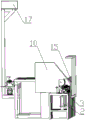
FIG. 2 is a schematic structural view of the present invention;
FIG. 3 is a left side view of FIG. 2;
FIG. 4 is a right side view of FIG. 2;
FIG. 5 is a top view of FIG. 2;
FIG. 6 is a schematic structural view of the present invention with the first protective cover and the second protective cover removed;
FIG. 7 is a perspective view of the present invention with the first and second shields removed;
wherein: landing leg 1, first cylinder 2, first arc layer board 3, second cylinder 4, second arc layer board 5, mount pad 6, pivot 7, rotary drum 8, leading wheel 9, first protection casing 10, deflector 11, rack 12, leading truck 13, hinge 14, pin 15, pillar 16, second protection casing 17, baffle 18, gyro wheel 19, first motor 20, first chain 21, second motor 22, second chain 23, rust cleaning cylinder 24, electric block 25.
Detailed Description
In the description of the present invention, it should also be noted that, unless otherwise explicitly specified or limited, the terms "disposed," "mounted," "connected," and "connected" are to be construed broadly, e.g., as meaning either a fixed connection, a removable connection, or an integral connection; can be mechanically or electrically connected; they may be connected directly or indirectly through intervening media, or they may be interconnected between two elements. The specific meaning of the above terms in the present invention can be understood in specific cases to those skilled in the art.
The technical solutions in the embodiments of the present invention will be described clearly and completely with reference to the accompanying drawings in the embodiments of the present invention, and it is obvious that the described embodiments are only some embodiments of the present invention, not all embodiments. Based on the embodiments in the present invention, all other embodiments obtained by a person skilled in the art without creative work belong to the protection scope of the present invention.
Example 1
As shown in fig. 1-7, a pot leg deruster comprises a support frame, wherein supporting legs 1 are uniformly installed at the bottom of the support frame, a placing frame 12 used for placing pot legs is installed in the front of the right side of the support frame, a hoisting device used for hoisting the pot legs is installed above the placing frame 12, the hoisting device comprises a supporting column 16 which is connected with the front side of the placing frame 12 and installed along the vertical direction, an electric hoist 25 installed at the top of the supporting column 16, and a second protective cover 17 is installed outside the electric hoist 25. The top of the placing frame 12 is provided with a guide frame 13 for rolling the pot legs towards the direction of the supporting frame. A plurality of limiting mechanisms are evenly arranged on the front side of the top of the placing rack 12, a baffle 18 is arranged on the front side of each limiting mechanism, and an arc-shaped groove matched with the pot legs is formed in the rear side face of each baffle 18. The limiting mechanism comprises a limiting plate vertically connected with the front side face of the top of the placing frame 12, an arc-shaped groove is formed in the top of the limiting plate, and rollers 19 are mounted on the front side and the rear side of the top of the limiting plate. The rear side of the guide frame 13 is hinged with the rear side of the top of the placing frame 12 through a hinge 14, a plurality of guide plates 11 corresponding to the guide frame 13 are evenly arranged on the front side of the top of the supporting frame along the length direction of the supporting frame, and the upper ends of the guide plates 11 are bent into an arc shape towards the direction of the guide frame 13. Electric block 25 hangs the jar leg and leaves rack 12, and the front side of leading truck 13 leaves rack 12, and the jar leg receives stopping of baffle 18, falls on the limiting plate, and the front side of leading truck 13 falls on rack 12 again, and the staff dials the jar leg from the limiting plate to leading truck 13 on, when the front side of leading truck 13 leaves rack 12 once more, leading truck 13 forms the slope, and the jar leg rolls towards the direction of support frame. The pot legs are carried without manual force in the whole process, and time and labor are saved.
The top installation of support frame is used for ordering about the drive arrangement that the jar leg moved from right to left, drive arrangement includes a plurality of mount pads 6 of the length direction evenly mounted along the support frame, pivot 7 in mount pad 6 is adorned through the bearing, the suit is just located the rotary drum 8 between two adjacent mount pads 6 in pivot 7, length direction evenly mounted along the support frame and with a plurality of leading wheels 9 of rotary drum 8 matched with, the front end slope right of leading wheel 9, contained angle between leading wheel 9 and the rotary drum 8 is 60, the top rear side of support frame is along a plurality of shelves poles 15 that are used for preventing the length direction installation of support frame outside the jar leg from rolling off. The left side of the placing frame 12 is provided with a driving mechanism for driving the rotating shaft 7 to rotate, and the driving mechanism comprises a first motor 20 positioned at the bottom of the supporting frame, a first chain wheel which is installed at the output end of the first motor 20 and coaxially rotates with the output end of the first motor 20, a second chain wheel which is sleeved on the rotating shaft 7, and a first chain 21 which is used for connecting the first chain wheel and the second chain wheel. The first motor 20 works, the first chain 21 drives the rotating shaft 7 to rotate, the rotating drum 8 is matched with the guide wheel 9, the tank leg between the rotating drum 8 and the guide wheel 9 is driven to move leftwards, and the moving process is smooth and reliable. The left side of the placing frame 12 is provided with a derusting mechanism for derusting, and the derusting mechanism comprises a second motor 22 arranged above the supporting frame, a third chain wheel arranged at the output end of the second motor 22 and rotating coaxially with the output end of the second motor 22, a derusting roller 24 arranged above the supporting frame, a roller shaft arranged at the right side of the derusting roller 24 and coinciding with the axis of the derusting roller 24, a fourth chain wheel sleeved at the right end of the roller shaft, and a second chain 23 used for connecting the third chain wheel and the fourth chain wheel. The second motor 22 works to drive the derusting roller 24 to continuously rotate, and derusting of the tank legs moving leftwards is continuously performed, so that the derusting effect is good, and the working efficiency is high. The first protective cover 10 is arranged outside the driving mechanism and the derusting mechanism. And a pushing-off mechanism for driving the tank legs to leave the supporting frame is arranged on the left side of the derusting mechanism. The pushing-away mechanism comprises two air cylinders uniformly arranged on the left side of the derusting mechanism along the length direction of the supporting frame and an arc-shaped supporting plate arranged on the top of the air cylinders. Two cylinders are including being located the left second cylinder 4 of first protection casing 10, be located the first cylinder 2 of support frame left end, the arc layer board includes the first arc layer board 3 of being connected with the top of first cylinder 2, the second arc layer board 5 of being connected with second cylinder 4, the jar leg that the rust cleaning finishes lasts and moves to the arc layer board left on, first cylinder 2 and the work of second cylinder 4, promote first arc layer board 3 and the upward movement of second arc layer board 5 simultaneously, the jar leg rolls from first arc layer board 3 and second arc layer board 5, whole process work is smooth, can last automatic rust cleaning, high work efficiency, time saving and labor saving.
During normal work, the electric hoist 25 lifts the pot legs to leave the placing rack 12, the front side of the guide frame 13 leaves the placing rack 12, the pot legs are blocked by the baffle plate 18 and fall on the limiting plate, the front side of the guide frame 13 falls on the placing rack 12 again, workers shift the pot legs from the limiting plate to the guide frame 13, when the front side of the guide frame 13 leaves the placing rack 12 again, the guide frame 13 forms a slope, the pot legs roll away towards the supporting frame and roll into the space between the rotary drum 8 and the guide wheel 9 under the guiding action of the guide plate 11, the first motor 20 works, the first chain 21 drives the rotary shaft 7 to rotate, the rotary drum 8 is matched with the guide wheel 9 to drive the pot legs between the rotary drum 8 and the guide wheel 9 to move leftwards, the moving process is smooth and reliable, the second motor 22 works to drive the derusting roller 24 to continuously rotate, the left-moving pot legs are continuously derusted, the derusting effect is good, work efficiency is high, and the jar leg that the rust cleaning finishes continuously moves to the arc layer board left on, and first cylinder 2 and the work of second cylinder 4 promote first arc layer board 3 and the 5 rebound of second arc layer board simultaneously, and the jar leg rolls from first arc layer board 3 and second arc layer board 5, and whole process work is smooth, can continuously automatic rust cleaning, and work efficiency is high, labour saving and time saving.
Finally, it should be noted that: although the present invention has been described in detail with reference to the foregoing embodiments, it will be apparent to those skilled in the art that modifications and variations can be made in the embodiments or in part of the technical features of the embodiments without departing from the spirit and the scope of the invention.