CN211856943U - Digital underground pipeline detecting instrument - Google Patents
Digital underground pipeline detecting instrument Download PDFInfo
- Publication number
- CN211856943U CN211856943U CN202020439634.8U CN202020439634U CN211856943U CN 211856943 U CN211856943 U CN 211856943U CN 202020439634 U CN202020439634 U CN 202020439634U CN 211856943 U CN211856943 U CN 211856943U
- Authority
- CN
- China
- Prior art keywords
- buffer spring
- welding
- base
- post
- underground pipeline
- Prior art date
- Legal status (The legal status is an assumption and is not a legal conclusion. Google has not performed a legal analysis and makes no representation as to the accuracy of the status listed.)
- Expired - Fee Related
Links
Images


Abstract
The utility model discloses a digital underground pipeline detecting instrument, which comprises a base, a plurality of positioning holes are evenly arranged on a stand column, the lower end of the side surface of a lifting column is connected with a positioning bolt through a thread, the upper end of the lifting column is fixedly provided with a pipeline detecting instrument body, a detector is fixedly arranged in a fixed groove plate through a screw, a wheel is rotatably arranged on an installation block through a rotating shaft, a limiting plate is welded at the top of a movable column, a first buffer spring is sleeved on the movable column, a second buffer spring is sleeved on the movable column, the utility model installs the pipeline detecting instrument body on the lifting column, and the height of the lifting column can be adjusted through the pushing of the wheel, thereby being time-saving and labor-saving, being suitable for operators with different heights, and ensuring the detection effect by installing the detector in the fixed groove plate, the first buffer spring and the second buffer spring can prevent the use performance of the detector from being influenced by vibration.
Description
Technical Field
The utility model relates to a pipeline detection device technical field specifically is a digital pipeline detection instrument.
Background
The underground pipeline detector can quickly and accurately detect the position, the trend and the depth of underground tap water pipelines, metal pipelines, cables and the like and the position and the size of a damaged point of an anticorrosive coating of a steel pipeline under the condition of not damaging ground covering soil. The device is one of the necessary instruments for transforming, maintaining and generally surveying underground pipelines of tap water companies, gas companies, railway communication, industrial and mining and capital construction units.
At present, some digital underground pipeline detection instruments appear in the market, and these digital underground pipeline detection instruments are mostly hand-held type, need artifical bowing to survey one section road surface, can appear the ache symptom after bowing for a long time, especially to the higher staff of some heights more painfully, the detection inefficiency of this kind of mode, can't realize fixing of probe angle when using simultaneously, influence detection effect.
SUMMERY OF THE UTILITY MODEL
The utility model aims to provide a digital underground pipeline detector, which is characterized in that a pipeline detector body is fixedly arranged on a lifting column and is pushed to walk by wheels without manual holding, time and labor are saved, and the height of the lifting column can be adjusted by matching between a positioning hole and a positioning bolt, so that the digital underground pipeline detector can be suitable for operators with different heights; the angle that can guarantee the detector through installing the detector in fixed frid is fixed, ensures detection effect, can play the cushioning effect to the wheel when walking through first buffer spring and second buffer spring, prevents to shake the performance that influences the detector to solve the problem that proposes among the above-mentioned background art.
In order to achieve the above object, the utility model provides a following technical scheme: a digital underground pipeline detector comprises a base, wherein a stand column is welded at the top of the base and movably connected to the wall of a groove, the groove is formed in the bottom of a lifting column, a plurality of positioning holes are uniformly formed in the stand column, a positioning bolt is in threaded connection with the lower end of the side face of the lifting column, a movable bolt is in threaded connection with the positioning hole, a pipeline detector body is fixedly mounted at the upper end of the lifting column, a fixed groove plate is welded on the side face of the base, a detector is fixedly mounted in the fixed groove plate through a screw, a connecting rod is welded at the top end of the side face of the lifting column, a display screen is fixedly mounted on the connecting rod through a screw, a handle is welded at the upper end of the side face of the lifting column, a sleeve is welded at the bottom of the base, a movable cavity is formed in the sleeve, and a movable column is movably connected, the bottom welding of activity post has the installation piece, rotate through the pivot on the installation piece and install the wheel, the top welding of activity post has the limiting plate, first buffer spring has been cup jointed on the activity post, first buffer spring's one end fixed connection is at the lower surface of limiting plate, first buffer spring's other end fixed connection is at the bottom of the chamber in activity chamber, second buffer spring has been cup jointed on the activity post, second buffer spring's one end fixed connection is at telescopic lower surface, second buffer spring's other end fixed connection is at the upper surface of installation piece.
Preferably, the number of the handles is two, the two handles are welded on two sides of the lifting column, and the outer surface of each handle is sleeved with a rubber sleeve.
Preferably, the top of the base is fixedly provided with a storage battery through a screw.
Preferably, the storage box is welded to the top of the base.
Preferably, the surface of the wheel is sleeved with an anti-slip ring.
Preferably, the two sides of the movable cavity are provided with limit grooves, and the two sides of the limit plate are connected to the inner walls of the limit grooves in a sliding manner.
Compared with the prior art, the beneficial effects of the utility model are that:
1. the pipeline detector body is fixedly arranged on the lifting column and pushed to travel through the wheels, manual holding is not needed, time and labor are saved, and the height of the lifting column can be adjusted through matching between the positioning holes and the positioning bolts, so that the pipeline detector can be suitable for operators with different heights;
2. the angle that can guarantee the detector through installing the detector in fixed frid is fixed, ensures detection effect, can play the cushioning effect to the wheel when walking through first buffer spring and second buffer spring, prevents to shake the performance that influences the detector.
Drawings
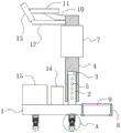
Fig. 1 is a schematic structural view of the present invention;
fig. 2 is a schematic cross-sectional view of the present invention;
fig. 3 is an enlarged schematic view of a portion a in fig. 2 according to the present invention.
In the figure: 1. a base; 2. a column; 3. a groove; 4. a lifting column; 5. positioning holes; 6. positioning the bolt; 7. a pipeline detector body; 8. fixing the groove plate; 9. a detector; 10. a connecting rod; 11. a display screen; 12. a handle; 13. a rubber sleeve; 14. a storage battery; 15. a storage box; 16. a sleeve; 17. a movable cavity; 18. a movable post; 19. mounting blocks; 20. a wheel; 21. a first buffer spring; 22. a second buffer spring; 23. and a limiting plate.
Detailed Description
The technical solutions in the embodiments of the present invention will be described clearly and completely with reference to the accompanying drawings in the embodiments of the present invention, and it is obvious that the described embodiments are only some embodiments of the present invention, not all embodiments. Based on the embodiments in the present invention, all other embodiments obtained by a person skilled in the art without creative work belong to the protection scope of the present invention.
Referring to fig. 1-3, the present invention provides a technical solution: a digital underground pipeline detector comprises a base 1, wherein an upright post 2 is welded at the top of the base 1, the upright post 2 is movably connected onto the wall of a groove 3, the groove 3 is arranged at the bottom of a lifting post 4, a plurality of positioning holes 5 are uniformly formed in the upright post 2, a positioning bolt 6 is in threaded connection with the lower end of the side surface of the lifting post 4, a movable threaded connection of the positioning bolt 6 is arranged in the positioning hole 5, a pipeline detector body 7 is fixedly arranged at the upper end of the lifting post 4, a fixed groove plate 8 is welded at the side surface of the base 1, a detector 9 is fixedly arranged in the fixed groove plate 8 through screws, a connecting rod 10 is welded at the top end of the side surface of the lifting post 4, a display screen 11 is fixedly arranged on the connecting rod 10 through screws, handles 12 are welded at the upper end of the side surface of the lifting post 4, the two handles 12 are welded at two, the hand is prevented from slipping, so that the pipeline detector body 7 is pushed to move conveniently;
the bottom of the base 1 is welded with a sleeve 16, a movable cavity 17 is formed in the sleeve 16, a movable column 18 is movably connected in the movable cavity 17, an installation block 19 is welded at the bottom of the movable column 18, a wheel 20 is rotatably installed on the installation block 19 through a rotating shaft, an anti-slip ring is sleeved on the surface of the wheel 20, friction between the wheel 20 and the ground is increased, the wheel 20 is prevented from slipping in the moving process, a limiting plate 23 is welded at the top of the movable column 18, limiting grooves are formed in two sides of the movable cavity 17, two sides of the limiting plate 23 are slidably connected to the inner wall of the limiting groove, the limiting plate 23 is limited, the wheel 20 is prevented from rotating due to the rotation of the limiting plate 23, a first buffer spring 21 is sleeved on the movable column 18, one end of the first buffer spring 21 is fixedly connected to the lower surface of the limiting plate 23, and the other end, second buffer spring 22 has been cup jointed on the activity post 18, the one end fixed connection of second buffer spring 22 is at the lower surface of sleeve 16, the other end fixed connection of second buffer spring 22 is at the upper surface of installation piece 19, there is battery 14 at base 1's top through screw fixed mounting, battery 14 can give the instrument power supply that needs at the detection in-process, base 1's top welding has storage tank 15, can store the various parts that the detection in-process needs.
The working principle is as follows: when the device is used, the height of the lifting column 4 is adjusted by adjusting the position between the positioning bolt 6 and the positioning hole 5, so that the height of the display screen 11 is suitable for the height of an operator, the operator can watch the height conveniently, the operator pushes the wheel 20 to move through the handle 12, and then the pipeline detector body 7 is controlled to move, in the moving process, the underground pipeline is detected through the detector 9, signals are transmitted to the pipeline detector body 7, the detected data are processed through the pipeline detector body 7, the detected data are displayed through the display screen 11, in the moving process, the buffer effect on the wheel 20 during walking can be achieved through the first buffer spring 21 and the second buffer spring 22, and the use performance of the detector 9 is prevented from being influenced by vibration.
Although embodiments of the present invention have been shown and described, it will be appreciated by those skilled in the art that changes, modifications, substitutions and alterations can be made in these embodiments without departing from the principles and spirit of the invention, the scope of which is defined in the appended claims and their equivalents.
Claims (6)
1. The utility model provides a digital pipeline detection instrument, includes base (1), its characterized in that: the top welding of base (1) has stand (2), stand (2) swing joint is on the cell wall of recess (3), the bottom at lift post (4) is seted up in recess (3), evenly seted up a plurality of locating hole (5) on stand (2), end screw thread connection has positioning bolt (6) under the side of lift post (4), positioning bolt's (6) removal threaded connection is in locating hole (5), the upper end fixed mounting of lift post (4) has pipeline detection instrument body (7), the side welding of base (1) has fixed frid (8), the inside of fixed frid (8) leads to screw fixed mounting has detector (9), the side top welding of lift post (4) has connecting rod (10), there is display screen (11) through screw fixed mounting on connecting rod (10), the welding of the side upper end of lift post (4) has handle (12), the welding of the bottom of base (1) has sleeve (16), movable chamber (17) has been seted up to the inside of sleeve (16), the inside swing joint of activity chamber (17) has movable post (18), the welding of the bottom of activity post (18) has installation piece (19), install wheel (20) through the pivot rotation on installation piece (19), the welding of the top of activity post (18) has limiting plate (23), first buffer spring (21) has been cup jointed on activity post (18), the one end fixed connection of first buffer spring (21) is at the lower surface of limiting plate (23), the other end fixed connection of first buffer spring (21) is at the end of the chamber of activity chamber (17), second buffer spring (22) has been cup jointed on activity post (18), the one end fixed connection of second buffer spring (22) is at the lower surface of sleeve (16), the other end of the second buffer spring (22) is fixedly connected to the upper surface of the mounting block (19).
2. The digital underground pipeline finder according to claim 1, wherein: the lifting column is characterized in that the number of the handles (12) is two, the handles (12) are welded on two sides of the lifting column (4), and a rubber sleeve (13) is sleeved on the outer surface of each handle (12).
3. The digital underground pipeline finder according to claim 1, wherein: the top of the base (1) is fixedly provided with a storage battery (14) through a screw.
4. The digital underground pipeline finder according to claim 1, wherein: the top welding of base (1) has storage tank (15).
5. The digital underground pipeline finder according to claim 1, wherein: the surface of the wheel (20) is sleeved with an anti-skid ring.
6. The digital underground pipeline finder according to claim 1, wherein: limiting grooves are formed in two sides of the movable cavity (17), and two sides of the limiting plate (23) are connected to the inner walls of the limiting grooves in a sliding mode.
Priority Applications (1)
| Application Number | Priority Date | Filing Date | Title |
|---|---|---|---|
| CN202020439634.8U CN211856943U (en) | 2020-03-31 | 2020-03-31 | Digital underground pipeline detecting instrument |
Applications Claiming Priority (1)
| Application Number | Priority Date | Filing Date | Title |
|---|---|---|---|
| CN202020439634.8U CN211856943U (en) | 2020-03-31 | 2020-03-31 | Digital underground pipeline detecting instrument |
Publications (1)
| Publication Number | Publication Date |
|---|---|
| CN211856943U true CN211856943U (en) | 2020-11-03 |
Family
ID=73137405
Family Applications (1)
| Application Number | Title | Priority Date | Filing Date |
|---|---|---|---|
| CN202020439634.8U Expired - Fee Related CN211856943U (en) | 2020-03-31 | 2020-03-31 | Digital underground pipeline detecting instrument |
Country Status (1)
| Country | Link |
|---|---|
| CN (1) | CN211856943U (en) |
Cited By (4)
| Publication number | Priority date | Publication date | Assignee | Title |
|---|---|---|---|---|
| CN113219548A (en) * | 2021-04-29 | 2021-08-06 | 广东新达测绘科技有限公司 | Digital underground pipeline detecting instrument with stable structure |
| CN113465667A (en) * | 2021-06-30 | 2021-10-01 | 贵州电网有限责任公司 | Insulated telescopic bending underground searchlighting instrument |
| CN113900149A (en) * | 2021-09-02 | 2022-01-07 | 中铁十八局集团有限公司 | Quick detection positioner of pre-buried PVC spool and tubular metal resonator |
| CN117108893A (en) * | 2023-10-24 | 2023-11-24 | 烟台国网中电电气有限公司 | Underground pipeline position detection device and method |
-
2020
- 2020-03-31 CN CN202020439634.8U patent/CN211856943U/en not_active Expired - Fee Related
Cited By (6)
| Publication number | Priority date | Publication date | Assignee | Title |
|---|---|---|---|---|
| CN113219548A (en) * | 2021-04-29 | 2021-08-06 | 广东新达测绘科技有限公司 | Digital underground pipeline detecting instrument with stable structure |
| CN113465667A (en) * | 2021-06-30 | 2021-10-01 | 贵州电网有限责任公司 | Insulated telescopic bending underground searchlighting instrument |
| CN113900149A (en) * | 2021-09-02 | 2022-01-07 | 中铁十八局集团有限公司 | Quick detection positioner of pre-buried PVC spool and tubular metal resonator |
| CN113900149B (en) * | 2021-09-02 | 2024-04-12 | 中铁十八局集团有限公司 | Quick detection positioning device for embedded PVC (polyvinyl chloride) wire pipes and metal pipes |
| CN117108893A (en) * | 2023-10-24 | 2023-11-24 | 烟台国网中电电气有限公司 | Underground pipeline position detection device and method |
| CN117108893B (en) * | 2023-10-24 | 2024-01-09 | 烟台国网中电电气有限公司 | Underground pipeline position detection device and method |
Similar Documents
| Publication | Publication Date | Title |
|---|---|---|
| CN211856943U (en) | Digital underground pipeline detecting instrument | |
| CN210664476U (en) | Geographic measurement mapping equipment convenient to remove | |
| CN212672857U (en) | Total station | |
| CN211877037U (en) | Measuring instrument for geological engineering surveying and mapping | |
| CN211085742U (en) | Sampling device for geological mineral exploration | |
| CN208765717U (en) | A kind of novel civil engineering measuring instrument fixed support device | |
| CN217058806U (en) | Building slope warning device for building monitoring | |
| CN213780372U (en) | Be used for mine geological environment monitoring devices | |
| CN115823455A (en) | Multifunctional mapping equipment and using method thereof | |
| CN213336097U (en) | Special gradient measuring device of building engineering | |
| CN210440910U (en) | Hydraulic engineering is with surveying device convenient to carry | |
| CN210050522U (en) | Can place total powerstation on various ground | |
| CN210268675U (en) | Measuring tool for engineering supervision | |
| CN220930746U (en) | Measuring device for chemical engineering investigation | |
| CN216283520U (en) | Portable total station | |
| CN210800590U (en) | Portable measuring instrument | |
| CN220709376U (en) | Pipeline detection system | |
| CN214470947U (en) | Quick change mechanism for detecting head of underground pipeline detector | |
| CN220326030U (en) | Building measurement level | |
| CN218378782U (en) | Support frame is measured in road construction | |
| CN213245435U (en) | Centering device is used in cadastral survey and drawing | |
| CN213843552U (en) | Underground pipeline detecting instrument | |
| CN219223727U (en) | Special gradient measuring device of building engineering | |
| CN215367179U (en) | Measure measuring apparatu of foundation ditch side slope | |
| CN220847494U (en) | Stable survey positioning structure |
Legal Events
| Date | Code | Title | Description |
|---|---|---|---|
| GR01 | Patent grant | ||
| GR01 | Patent grant | ||
| CF01 | Termination of patent right due to non-payment of annual fee |
Granted publication date: 20201103 Termination date: 20210331 |
|
| CF01 | Termination of patent right due to non-payment of annual fee |