CN211813140U - Crane counterweight structure and lorry-mounted crane - Google Patents
Crane counterweight structure and lorry-mounted crane Download PDFInfo
- Publication number
- CN211813140U CN211813140U CN201922411573.4U CN201922411573U CN211813140U CN 211813140 U CN211813140 U CN 211813140U CN 201922411573 U CN201922411573 U CN 201922411573U CN 211813140 U CN211813140 U CN 211813140U
- Authority
- CN
- China
- Prior art keywords
- counterweight
- support
- cylinder
- crane
- lorry
- Prior art date
- Legal status (The legal status is an assumption and is not a legal conclusion. Google has not performed a legal analysis and makes no representation as to the accuracy of the status listed.)
- Active
Links
Images


Abstract
The utility model relates to the technical field of crane equipment, and discloses a crane counterweight structure and a lorry-mounted crane, which comprises a counterweight support and a positioning hole group arranged on a rotary table of the crane, wherein the counterweight support comprises a support body and a counterweight body connected on the support body, the support body is provided with a fixed hole group which can be matched with the positioning hole group, and a fixed pin is inserted between the positioning hole group and the fixed hole group for connection; still including locating swing hydro-cylinder support, the supporting hydro-cylinder support on the carriage, the articulated supporting hydro-cylinder that is connected with on the supporting hydro-cylinder support, the supporting hydro-cylinder includes the cylinder body and can flexible supporting end in the cylinder body, supporting end can vertical support the support body, the cylinder body with articulated swing hydro-cylinder that is connected with between the swing hydro-cylinder support, in order to drive the supporting hydro-cylinder swing. The utility model discloses be convenient for install the counter weight on lorry crane fast, improved lorry crane's security.
Description
Technical Field
The utility model relates to a crane equipment technical field especially relates to a hoist counter weight structure and lorry crane.
Background
In engineering construction, large-tonnage lorry-mounted cranes are used more and more. The lorry-mounted crane has the advantages that the lifted heavy object can be directly placed in the carriage of the truck and can be directly transported away by using the lorry-mounted crane without finding a truck additionally for transportation. This also limits the lifting capacity of the lorry-mounted crane, the size of the weight that the lorry-mounted crane can lift and the weight of the weight are greatly reduced. The purpose of the truck crane is mainly to lift a heavy object independently, and the weight and the size of the heavy object capable of being lifted are larger than those of the lorry-mounted crane.
Correspondingly, the tonnage of the lorry-mounted crane is also getting larger and larger, but most of the existing large-tonnage lorry-mounted cranes are not provided with special counterweight blocks behind the lorry-mounted cranes, so that when the lorry-mounted cranes work, a heavy object which can be used as a counterweight needs to be found on site to balance the whole body of the lorry-mounted crane, for example, when a forklift is arranged nearby, the forklift is pressed to the front of a carriage as the counterweight block. However, the hoisting capacity of the lorry-mounted crane is limited if no suitable weight is used as counterweight.
SUMMERY OF THE UTILITY MODEL
The utility model aims at providing a hoist counter weight structure and lorry crane can improve lorry crane's lifting capacity and security.
In order to realize the above-mentioned purpose, the utility model provides a hoist counterweight structure and lorry crane, include the counter weight support and locate the location punch combination on the hoist revolving stage, the counter weight support include the support body with connect in the counter weight body on the support body, be equipped with on the support body can with location punch combination complex fixed punch combination, insert between location punch combination and the fixed punch combination and establish the fixed pin and be connected.
As preferred scheme, still including locating swing hydro-cylinder support, the supporting hydro-cylinder support on the carriage, articulated connection has the supporting hydro-cylinder on the supporting hydro-cylinder support, the supporting hydro-cylinder includes the cylinder body and can flexible supporting end in the cylinder body, supporting end can vertical support the support body, the cylinder body with articulated connection has the swing hydro-cylinder between the swing hydro-cylinder support, in order to drive the supporting hydro-cylinder swing.
As an optimal scheme, the lifting device further comprises a counterweight telescopic oil cylinder, two ends of the counterweight telescopic oil cylinder are respectively hinged with the counterweight body and the frame body, and the counterweight telescopic oil cylinder is horizontally arranged to push the counterweight body to move back and forth in the frame body.
As preferred scheme, the counter weight body is including fixed counter weight body, fixed counter weight body top is connected with the balancing weight reference column, can fix a position on the balancing weight reference column and place standard balancing weight.
Preferably, the counterweight telescopic oil cylinder is hinged with the fixed counterweight body.
Preferably, the positioning hole group includes a first positioning hole and a second positioning hole, and the fixing hole group includes a first fixing hole and a second fixing hole corresponding to the first positioning hole and the second positioning hole.
As preferred scheme, the quantity of balancing weight reference column is two.
The utility model also provides a lorry crane who has foretell arbitrary any hoist counter weight structure.
The utility model provides a hoist counterweight structure installs the revolving stage of lorry crane with the counter weight support on for the lorry crane can be through the counterweight body counter weight of counter weight support, and this hoist counterweight structure is convenient for install and use, is convenient for install the counter weight on the lorry crane on the scene, convenient to use.
Further, the utility model discloses when using, swing cylinder drive supporting cylinder rotates for the supporting cylinder reachs vertical position, utilize lorry crane self lift by crane the function with the counter weight support place the supporting cylinder on, rotate the revolving stage of lorry crane to the position of installation counter weight support, control supporting cylinder with the lifting of counter weight support, make the counter weight support reachs mounted position, through fixing punch combination and location punch combination installation, be convenient for more on-the-spot installation counter weight on lorry crane.
The utility model also provides a have foretell hoist counterweight structure, be convenient for install fast at the scene, improved lorry crane's stability and lifting capacity.
Drawings
Fig. 1 is a schematic structural diagram of a counterweight structure of a crane in an installation completed state in an embodiment of the present invention;
fig. 2 is a schematic structural diagram of a crane counterweight structure at the end of an installation process in an embodiment of the present invention;
fig. 3 is a schematic structural diagram of a counterweight structure of a crane in an embodiment of the present invention during installation;
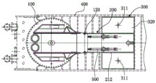
fig. 4 is a schematic top view of a crane counterweight structure in an embodiment of the present invention;
in the figure, 100, a crane turntable; 110. positioning a hole group; 111. a first positioning hole; 112. a second positioning hole; 120. a fixing pin; 200. a counterweight bracket; 210. a frame body; 211. a base plate; 212. a side plate; 220. fixing the hole group; 221. a first fixing hole; 222. a second fixing hole; 300. a counterweight body; 310. fixing a counterweight body; 311. a counterweight positioning column; 320. a standard balancing weight; 400. a carriage; 410. a swing oil cylinder support; 420. a support for supporting the cylinder; 430. a support cylinder; 431. a cylinder body; 432. a support end; 440. a swing oil cylinder; 500. the counterweight telescopic oil cylinder.
Detailed Description
The following detailed description of the embodiments of the present invention is provided with reference to the accompanying drawings and examples. The following examples are intended to illustrate the invention, but are not intended to limit the scope of the invention.
As shown in fig. 1 to 4, the utility model discloses a crane counterweight structure and lorry-mounted crane of preferred embodiment is convenient for install in lorry-mounted crane's carriage, and convenient and fast can improve lorry-mounted crane's stability and security simultaneously.
Based on the above technical scheme, provide a hoist counterweight structure in this embodiment, including counter weight support 200 and locate the location punch combination 110 on hoist revolving stage 100, wherein, counter weight support 200 installs on hoist revolving stage 100 when using, and location punch combination 110 is used for installing counter weight support 200, can improve lorry crane's stability.
Specifically, the counterweight bracket 200 includes a bracket body 210 and a counterweight body 300 connected to the bracket body 210, and the counterweight body 300 is a main weight used as a counterweight in the counterweight structure of the crane. Wherein, the weight bracket 200 is used as a whole to directly serve as a weight in use.
Specifically, the frame body 210 of the counterweight support 200 is provided with a fixing hole group 220 capable of being engaged with the positioning hole group 110, and the fixing hole group 220 is used for mounting the counterweight support 200 to the crane turret 100 through the positioning hole group 110. When the counterweight support 200 is installed, the fixing pins 120 are inserted between the positioning hole group 110 and the fixing hole group 220, and the counterweight support is installed on the crane turret 100.
The frame body 210 includes a bottom plate 211 and a side plate 212 vertically connected to the bottom plate, the fixing hole group 220 is disposed on the side plate 212, and the fixing hole group 220 is used as a fixing hole.
Preferably, the utility model discloses still including locating swing cylinder support 410, the supporting cylinder support 420 on carriage 400, carriage 400 is the packing box of lorry crane, and lorry crane's davit also is established in carriage 400. Wherein, the swing cylinder support 410 and the support cylinder support 420 may be connected to the bottom of the car 400 by welding or bolts.
Specifically, a support cylinder 430 is hinged to the support cylinder support 420, the support cylinder 430 includes a cylinder body 431 and a support end 432 capable of telescoping in the cylinder body 431, and the support cylinder 430 drives the support end 432 to telescope in the cylinder body 431 by hydraulic oil.
Specifically, the support end 432 can vertically support the frame body 210, and a swing cylinder 440 is hinged between the cylinder body 431 and the swing cylinder support 410 to drive the support cylinder 430 to swing. This kind of structure makes the utility model discloses when need not the counter weight, only need place supporting cylinder 430, swing hydro-cylinder 440 level in carriage 400, and then practiced thrift the space of supporting cylinder 430, swing hydro-cylinder 440 department in carriage 400. When the balance weight is installed, the support oil cylinder 430 is driven to swing by the swing oil cylinder 440, and the support end 432 vertically supports the frame body 210 to be lifted, so that the frame body 210 and the balance weight body 300 in the frame body 210 can be installed on the crane rotary table 100, and the installation on site is convenient.
As shown in fig. 1 to 3, in mounting the frame body 210, the frame body 210 is first hoisted by the crane turret 100, the boom of the crane turret 100 is controlled to reach the side of the positioning hole group 110, the frame body 210 is placed on the support cylinder 430, and then the crane turret 100 is operated to swing, the boom of the crane turret 100 is controlled to reach the opposite side of the positioning hole group 110, so that the positioning hole group 110 is aligned with the fixing hole group 220 of the frame body 210. Then control supporting cylinder 430 drive support body 210 and the weight body 300 rise, install support body 210 on location punch combination 110, dismantle support body 210 and also can go on according to this process, make the utility model discloses it is very convenient at on-the-spot installation and dismantlement.
Preferably, a counterweight telescopic cylinder 500 is further included, and the telescopic cylinder 500 is used for improving the use effect of the counterweight body 300. Specifically, two ends of the counterweight telescopic cylinder 500 are respectively hinged to the counterweight body 300 and the frame body 210, that is, one end of the counterweight telescopic cylinder 500 may be hinged to the bottom plate 211.
The counterweight telescopic cylinder 500 is horizontally arranged to push the counterweight body 300 to move back and forth in the frame body 210, so as to adjust the length of the force arm of the counterweight body 300 under the action of the counterweight body 300, and further improve the counterweight capacity of the counterweight body 300.
Preferably, the counterweight body 300 includes a fixed counterweight body 310, a counterweight positioning column 311 is connected to the top of the fixed counterweight body 310, and a standard counterweight 320 can be positioned on the counterweight positioning column 311. When in use, the number of the standard balancing weights 320 can be adjusted according to actual requirements, so as to adjust the balancing capability of the balancing weight body 300.
Preferably, the counterweight telescopic cylinder 500 is hinged to the fixed counterweight body 310, a support hinged to the counterweight telescopic cylinder 500 is left in the middle of the top of the fixed counterweight body 310, and the standard counterweight 320 is not placed above the support hinged to the counterweight telescopic cylinder 500, that is, the other end of the counterweight telescopic cylinder 500 is hinged to the fixed counterweight body 310, so that the fixed counterweight body 310 and the standard counterweight 320 can be integrally driven to move under the counterweight telescopic cylinder 500.
Preferably, the positioning hole set 110 includes a first positioning hole 111 and a second positioning hole 112, the fixing hole set 220 includes a first fixing hole 221 and a second fixing hole 222 which are correspondingly disposed with the first positioning hole 111 and the second positioning hole 112, and the frame body 210 can be stably connected to the crane turntable 100 through a two-hole structure.
Preferably, the number of the counterweight positioning columns 311 is two, the counterweight positioning columns 311 are disposed on two sides of the support hinged to the counterweight telescopic cylinder 500 on the fixed counterweight body 310, each counterweight positioning column 311 can be used for placing a standard counterweight 320, and the side wall of the standard counterweight 320 can be abutted to and positioned on the side plate 212.
The utility model also provides a lorry crane with foretell hoist counter weight structure, the on-the-spot installation of being convenient for, dismantle the counter weight, avoided the preceding high condition low at the back of whole car of lorry crane, improved lorry crane's security and stability.
The foregoing is only a preferred embodiment of the present invention, and it should be noted that, for those skilled in the art, a plurality of modifications and replacements can be made without departing from the technical principle of the present invention, and these modifications and replacements should also be regarded as the protection scope of the present invention.
Claims (8)
1. The utility model provides a hoist counter weight structure, its characterized in that includes the counter weight support and locates the location punch combination on the hoist revolving stage, the counter weight support include the support body and connect in counterweight body on the support body, be equipped with on the support body can with location punch combination complex fixed punch combination, insert between location punch combination and the fixed punch combination and establish the fixed pin and be connected.
2. The crane counterweight structure according to claim 1, further comprising a swing cylinder support and a support cylinder support which are arranged on the carriage, wherein the support cylinder support is hinged with a support cylinder, the support cylinder comprises a cylinder body and a support end which can extend and retract in the cylinder body, the support end can vertically support the frame body, and a swing cylinder is hinged between the cylinder body and the swing cylinder support to drive the support cylinder to swing.
3. The crane counterweight structure according to claim 2, further comprising a counterweight telescopic cylinder, wherein two ends of the counterweight telescopic cylinder are respectively hinged to the counterweight body and the frame body, and the counterweight telescopic cylinder is horizontally arranged to push the counterweight body to move back and forth in the frame body.
4. The crane counterweight structure of claim 3 wherein said counterweight body comprises a fixed counterweight body, a counterweight positioning post is connected to the top of said fixed counterweight body, and a standard counterweight can be positioned on said counterweight positioning post.
5. The crane counterweight structure of claim 4 wherein said counterweight extension cylinder is hingedly connected to said fixed counterweight body.
6. The crane counterweight structure of claim 5, wherein the positioning hole set comprises a first positioning hole and a second positioning hole, and the fixing hole set comprises a first fixing hole and a second fixing hole which are arranged corresponding to the first positioning hole and the second positioning hole.
7. The crane counterweight structure of claim 6 wherein said counterweight positioning posts are two in number.
8. A lorry-mounted crane having a crane counterweight structure as claimed in any one of claims 1 to 7.
Priority Applications (1)
| Application Number | Priority Date | Filing Date | Title |
|---|---|---|---|
| CN201922411573.4U CN211813140U (en) | 2019-12-28 | 2019-12-28 | Crane counterweight structure and lorry-mounted crane |
Applications Claiming Priority (1)
| Application Number | Priority Date | Filing Date | Title |
|---|---|---|---|
| CN201922411573.4U CN211813140U (en) | 2019-12-28 | 2019-12-28 | Crane counterweight structure and lorry-mounted crane |
Publications (1)
| Publication Number | Publication Date |
|---|---|
| CN211813140U true CN211813140U (en) | 2020-10-30 |
Family
ID=73036274
Family Applications (1)
| Application Number | Title | Priority Date | Filing Date |
|---|---|---|---|
| CN201922411573.4U Active CN211813140U (en) | 2019-12-28 | 2019-12-28 | Crane counterweight structure and lorry-mounted crane |
Country Status (1)
| Country | Link |
|---|---|
| CN (1) | CN211813140U (en) |
Cited By (2)
| Publication number | Priority date | Publication date | Assignee | Title |
|---|---|---|---|---|
| CN112777499A (en) * | 2021-01-29 | 2021-05-11 | 三一汽车起重机械有限公司 | Counterweight self-dismounting device, crane and counterweight dismounting method |
| CN113651253A (en) * | 2021-08-23 | 2021-11-16 | 合肥市春华起重机械有限公司 | Counterweight device of lorry-mounted crane |
-
2019
- 2019-12-28 CN CN201922411573.4U patent/CN211813140U/en active Active
Cited By (4)
| Publication number | Priority date | Publication date | Assignee | Title |
|---|---|---|---|---|
| CN112777499A (en) * | 2021-01-29 | 2021-05-11 | 三一汽车起重机械有限公司 | Counterweight self-dismounting device, crane and counterweight dismounting method |
| CN112777499B (en) * | 2021-01-29 | 2023-05-02 | 三一汽车起重机械有限公司 | Counterweight self-dismounting device, crane and counterweight dismounting method |
| CN113651253A (en) * | 2021-08-23 | 2021-11-16 | 合肥市春华起重机械有限公司 | Counterweight device of lorry-mounted crane |
| CN113651253B (en) * | 2021-08-23 | 2023-12-29 | 合肥市春华起重机械有限公司 | Counterweight device of lorry-mounted crane |
Similar Documents
| Publication | Publication Date | Title |
|---|---|---|
| CN202463955U (en) | Non-snubbing equipment trailer | |
| US3777900A (en) | Building crane | |
| CN211813140U (en) | Crane counterweight structure and lorry-mounted crane | |
| CN202391339U (en) | Rotary drilling rig with automatically assembled and disassembled balance weight and adjustable barycenter | |
| AU2016204008A1 (en) | Hopper Handling Kit and Apparatus | |
| KR20140086385A (en) | Combination apparatus of coupling of motor for ship | |
| CN215479354U (en) | On-load deflection device and crane | |
| CN209758878U (en) | Hoisting accessory for mechanical equipment | |
| CN103420281B (en) | The attaching/detaching apparatus of hoisting crane and accessory structure thereof, method for dismounting and installation method | |
| KR20120001291A (en) | Trolley for tower crane and luffing crane | |
| CN203486803U (en) | Crane, counterweight device and rope assembly hanging mechanism | |
| CN114608383B (en) | Arrow body erecting device | |
| CN109879177A (en) | A kind of efficient boom hoisting for highway construction construction | |
| CN212832472U (en) | Small-tonnage three-degree-of-freedom crane | |
| CN213202180U (en) | Rotary table, movable counterweight mechanism and crane | |
| CN214495527U (en) | Movable hand chain block lifting support | |
| CN205653077U (en) | Tower crane for building site of band shift dynamic formula scaffold frame | |
| CN210529812U (en) | Special support for lifting large-scale component of excavator | |
| CN202369291U (en) | Winch mounting structure of automobile crane | |
| CN107176540B (en) | A kind of docking facilities for large-tonnage cargo transfer | |
| CN215594211U (en) | Variable-load counterweight device and working machine | |
| CN215711262U (en) | Hydraulic cantilever crane | |
| CN203833514U (en) | Special lorry-mounted crane for railway | |
| CN220766290U (en) | Portable mechanical equipment installs plummer | |
| CN213171227U (en) | Crane cantilever convenient to disassemble and assemble |
Legal Events
| Date | Code | Title | Description |
|---|---|---|---|
| GR01 | Patent grant | ||
| GR01 | Patent grant | ||
| PE01 | Entry into force of the registration of the contract for pledge of patent right | ||
| PE01 | Entry into force of the registration of the contract for pledge of patent right |
Denomination of utility model: A crane counterweight structure and truck mounted crane Effective date of registration: 20220721 Granted publication date: 20201030 Pledgee: Shaoguan Rural Commercial Bank Co.,Ltd. Pledgor: Shaoguan liput Construction Machinery Co.,Ltd. Registration number: Y2022980010923 |