CN211739736U - Raw material drying equipment is used in wood preservative processing - Google Patents
Raw material drying equipment is used in wood preservative processing Download PDFInfo
- Publication number
- CN211739736U CN211739736U CN201921952341.3U CN201921952341U CN211739736U CN 211739736 U CN211739736 U CN 211739736U CN 201921952341 U CN201921952341 U CN 201921952341U CN 211739736 U CN211739736 U CN 211739736U
- Authority
- CN
- China
- Prior art keywords
- fixedly connected
- wall
- tank body
- close
- drying cylinder
- Prior art date
- Legal status (The legal status is an assumption and is not a legal conclusion. Google has not performed a legal analysis and makes no representation as to the accuracy of the status listed.)
- Active
Links
Images

Abstract
The utility model discloses a raw materials drying equipment is used in antiseptic processing of wood, which comprises a tank body, the first motor of jar body top fixedly connected with, jar body bottom is close to the punishment of the left and right sides and has welded the base respectively, jar body top left and right sides is fixedly connected with inlet pipe respectively, and the inlet pipe is linked together with the inside of the jar body, the internal bull stick that is provided with of jar, the inner chamber top swing joint of bearing and the jar body is passed through on the top of bull stick, and the top of bull stick passes the inner circle of bearing and the output shaft fixed connection of first motor, the left and right sides of bull stick is provided with the shower nozzle respectively, and the shower nozzle is close to mutually with the inner wall of the jar body, jar body left and right sides outer wall is close to top department and installs the fan respectively, the air duct has been cup jointed on, High drying efficiency and the like.
Description
Technical Field
The utility model relates to a wood preservative processing raw materials drying equipment technical field specifically is a wood preservative processing is with raw materials drying equipment.
Background
The drying equipment is one of indispensable equipment in the wood preservative raw material processing industry, and is also called as a dryer and a dryer, and the wood preservative processing raw material can prolong the storage time after being dried and is convenient for further processing and use. The drying equipment utilizes heat energy to reduce the moisture of the raw material, drying operation is carried out on the wood preservative processing raw material, the operation is divided into different types such as convection type, conduction type, radiation type, dielectric type and the like, and the drying equipment enables the moisture in the wood preservative processing raw material to be vaporized and escaped through the heat energy so as to obtain the dried solid raw material. Since natural drying is far from meeting the requirements of production development, various mechanized dryers are increasingly widely used. But the existing drying equipment can not well dry the wood preservative processing raw materials, and has poor applicability, thereby greatly influencing the working efficiency.
SUMMERY OF THE UTILITY MODEL
The utility model provides a technical problem lie in overcoming defects such as prior art's availability factor is low, drying efficiency is low, provides a raw materials drying equipment is used in antiseptic processing of wood. The raw material drying equipment for processing the wood preservative has the characteristics of high use efficiency, high drying efficiency and the like.
In order to achieve the above object, the utility model provides a following technical scheme: a raw material drying device for processing wood preservative comprises a tank body, wherein a first motor is fixedly connected to the top of the tank body, bases are welded at positions, close to the left side and the right side, of the bottom of the tank body respectively, a feed pipe is fixedly connected to the left side and the right side of the top of the tank body respectively, the feed pipe is communicated with the inside of the tank body, a rotating rod is arranged in the tank body, the top end of the rotating rod is movably connected with the top of an inner cavity of the tank body through a bearing, the top end of the rotating rod penetrates through an inner ring of the bearing and is fixedly connected with an output shaft of the first motor, nozzles are arranged at the left side and the right side of the rotating rod respectively, the nozzles are close to the inner wall of the tank body, fans are installed at positions, close to the tops, of the outer walls of the left side and the right side of, a drying bin is arranged below the rotating rod, fixing plates are respectively and fixedly connected at the positions, close to the left side and the right side, of the top of the inner cavity of the tank body, the bottom of the fixed plate is movably connected with the drying bin through a bearing, the outer walls of the left side and the right side of the drying bin close to the bottom are respectively and fixedly connected with a fixed block, a compression spring is fixedly connected between the side wall of the fixed block and the inner wall of the tank body, a first hydraulic rod is respectively arranged above the compression spring, two ends of the first hydraulic rod are respectively and fixedly connected with the inner wall of the tank body and the outer wall of the drying bin, the side walls of the left side and the right side of the rotating rod are respectively provided with a plurality of first stirring rods which are uniformly distributed along the vertical direction, the bottom end of the rotating rod is fixedly connected with a second stirring rod, a drying cylinder is arranged in the tank body and close to the bottom, the top of the drying cylinder is fixedly connected with a first discharging pipe, and the first discharging pipe is communicated with the inside of the drying cylinder.
Preferably, a second motor is fixedly connected to the right outer wall of the tank body opposite to the drying cylinder, a first bevel gear is sleeved above the outer wall of the drying cylinder, a second bevel gear is meshed with the right side of the first bevel gear, the right side wall of the second bevel gear is movably connected with the right inner wall of the tank body through a rotating shaft and a bearing, the right end of the rotating shaft on the right side wall of the second bevel gear penetrates through an inner ring of the bearing and is fixedly connected with an output shaft of the second motor, fixing rods are fixedly connected to the positions, close to the bottom, of the outer walls of the left side and the right side of the drying cylinder respectively, the fixing rods and the end, far away from the drying cylinder, of the fixing rods are in sliding connection with the inner wall of the tank body, heating plates are fixedly connected to the inner wall of the drying cylinder, a movable bottom plate is arranged at the bottom of the drying cylinder, and the openings of the two U-shaped plates are opposite, the side walls of the U-shaped plates are fixedly connected with the outer wall of the drying cylinder, the bottom of the inner cavity of each U-shaped plate is movably connected with a second hydraulic rod through a rotating shaft and a bearing, and the rear wall of the second hydraulic rod is close to the top and is movably connected with the bottom of the movable bottom plate through a rotating shaft and a bearing.
Preferably, the bottom of the inner cavity of the tank body is fixedly connected with a second discharge pipe, the side wall of the U-shaped plate is fixedly connected with the second discharge pipe, and the bottom of the tank body is provided with a discharge hole matched with the second discharge pipe.
Preferably, the fan is close to two connecting rods of fixedly connected with on the lateral wall of one side of the jar body, the one end that connecting rod and fan kept away from mutually and the outer wall fixed connection of the jar body, and jar body about the lateral wall be close to top department offer with air duct assorted through-hole, two the connecting rod uses the central axis of air duct to be symmetry setting from top to bottom as the symmetry axis.
Preferably, the included angle between the bottom of the first stirring rod and the side wall of the rotating rod is an obtuse angle, and the second stirring rod is horizontally arranged.
Preferably, an included angle between the bottom of the second hydraulic rod and the bottom of the movable bottom plate is an obtuse angle, and the two second hydraulic rods are arranged in a bilateral symmetry mode by taking the central axis of the drying cylinder as a symmetry axis.
Preferably, the end of the fixed rod far away from the drying cylinder is provided with a pulley, and the inner wall of the tank body is provided with an annular chute matched with the pulley.
Compared with the prior art, the beneficial effects of the utility model are that:
1. in the technical scheme, the first motor, the rotating rod, the first stirring rod and the second stirring rod are matched with each other, so that the first motor can drive the rotating rod, the first stirring rod and the second stirring rod to rotate, the raw materials are fully stirred and turned, the raw materials can be uniformly heated, and the drying efficiency of the raw materials can be effectively improved;
2. in the technical scheme, the first bevel gear, the second bevel gear, the drying cylinder and the heating sheet are matched with each other, so that the second motor can drive the second bevel gear to rotate forwards or backwards, the first bevel gear meshed with the second bevel gear rotates along the horizontal direction through the rotation of the second bevel gear, and the drying cylinder sleeved with the second bevel gear is further driven to rotate, so that the raw materials are fully rolled, the purpose of uniform heating is achieved, and the drying efficiency and the use efficiency of the raw materials can be effectively improved;
3. in this technical scheme, through mutually supporting between dry storehouse, first hydraulic stem and the compression spring, can realize that first hydraulic stem pulling dry storehouse removes to the left and right sides respectively to open dry storehouse bottom, make the raw materials slide into dry section of thick bamboo through first discharging pipe and get into next dry process, thereby realize that the raw materials obtains further abundant dry effect, can effectual improvement its work efficiency.
Drawings
Fig. 1 is a schematic structural view of the present invention;
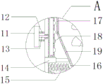
FIG. 2 is an enlarged view of FIG. 1 at A;
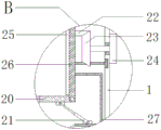
fig. 3 is an enlarged view of fig. 1 at B.
Reference numbers in the figures: 1. a tank body; 2. a base; 3. a feed pipe; 4. fixing the rod; 5. a second discharge pipe; 6. A first motor; 7. a rotating rod; 8. a first stirring rod; 9. a second stirring rod; 10. a first discharge pipe; 11. A fan; 12. a connecting rod; 13. an air duct; 14. a first hydraulic lever; 15. a compression spring; 16. a fixed block; 17. a fixing plate; 18. a spray head; 19. a drying bin; 20. a movable bottom plate; 21. a second hydraulic rod; 22. a first bevel gear; 23. a second bevel gear; 24. a second motor; 25. a heating plate; 26. a drying cylinder; 27. a U-shaped plate.
Detailed Description
The technical solutions in the embodiments of the present invention will be described clearly and completely with reference to the accompanying drawings in the embodiments of the present invention, and it is obvious that the described embodiments are only some embodiments of the present invention, not all embodiments. Based on the embodiments in the present invention, all other embodiments obtained by a person skilled in the art without creative work belong to the protection scope of the present invention.
Referring to fig. 1-3, the present invention provides a technical solution: a raw material drying device for processing wood preservative comprises a tank body 1, wherein the top of the tank body 1 is fixedly connected with a first motor 6, bases 2 are respectively welded at the positions, close to the left side and the right side, of the bottom of the tank body 1, feed pipes 3 are respectively fixedly connected with the left side and the right side of the top of the tank body 1, the feed pipes 3 are communicated with the inside of the tank body 1, a rotating rod 7 is arranged in the tank body 1, the top end of the rotating rod 7 is movably connected with the top of an inner cavity of the tank body 1 through a bearing, the top end of the rotating rod 7 penetrates through an inner ring of the bearing and is fixedly connected with an output shaft of the first motor 6, spray heads 18 are respectively arranged at the left side and the right side of the rotating rod 7, the spray heads 18 are close to the inner wall of the tank body 1, fans 11 are respectively installed at the positions, close to the tops of, the air duct 13 is communicated with the inside of the spray head 18, two connecting rods 12 are fixedly connected on the side wall of one side of the fan 11 close to the tank body 1, the end of the connecting rod 12 far away from the fan 11 is fixedly connected with the outer wall of the tank body 1, a through hole matched with the air duct 13 is arranged at the position of the left side wall and the right side wall of the tank body 1 close to the top, the two connecting rods 12 are arranged up and down symmetrically by taking the central axis of the air duct 13 as a symmetry axis, a drying bin 19 is arranged below the rotating rod 7, fixing plates 17 are respectively and fixedly connected at the positions of the top of the inner cavity of the tank body 1 close to the left side and the right side, the bottom of the fixing plate 17 is movably connected with the drying bin 19 through a bearing, fixing blocks 16 are respectively and fixedly connected at the positions of the left side wall and the right, the two ends of the first hydraulic rod 14 are respectively fixedly connected with the inner wall of the tank body 1 and the outer wall of the drying bin 19, the first hydraulic rod 14 and the compression spring 15 are mutually matched, so that the first hydraulic rod 14 can pull the drying bin 19 to respectively move towards the left side and the right side, the bottom of the drying bin 19 is opened, raw materials are enabled to slide into the drying cylinder 26 through the first discharge pipe 10 to enter the next drying procedure, further and fully dry the raw materials, the working efficiency of the drying bin can be effectively improved, the side walls of the left side and the right side of the rotating rod 7 are respectively provided with a plurality of first stirring rods 8 which are uniformly distributed along the vertical direction, the bottom end of the rotating rod 7 is fixedly connected with the second stirring rod 9, the included angle between the bottom of the first stirring rod 8 and the side wall of the rotating rod 7 is an obtuse angle, the second stirring rod 9 is horizontally arranged, and the first motor 6, the rotating rod 7, the first stirring rods 8 and the second stirring rod, the first motor 6 can drive the rotating rod 7, the first stirring rod 8 and the second stirring rod 9 to rotate, so that the raw materials are fully stirred and turned, the raw materials can be uniformly heated, and the drying efficiency of the raw materials can be effectively improved;
a drying cylinder 26 is arranged in the tank body 1 close to the bottom, a first discharging pipe 10 is fixedly connected to the top of the drying cylinder 26, the first discharging pipe 10 is communicated with the inside of the drying cylinder 26, a second motor 24 is fixedly connected to the right outer wall of the tank body 1 opposite to the drying cylinder 26, a first bevel gear 22 is sleeved above the outer wall of the drying cylinder 26, a second bevel gear 23 is meshed with the right side of the first bevel gear 22, the right side wall of the second bevel gear 23 is movably connected with the right inner wall of the tank body 1 through a rotating shaft and a bearing, the right end of the rotating shaft on the right side wall of the second bevel gear 23 penetrates through the inner ring of the bearing to be fixedly connected with the output shaft of the second motor 24, fixing rods 4 are fixedly and respectively connected to the outer walls of the left side and the right side of the drying cylinder 26 close to the bottom, one end of the fixing rod 4 far away from the drying cylinder 26 is slidably connected with the inner, an annular sliding groove matched with the pulley is arranged on the inner wall of the tank body 1, a heating sheet 25 is fixedly connected with the inner wall of the drying cylinder 26, a movable bottom plate 20 is arranged at the bottom of the drying cylinder 26, the left side and the right side of the movable bottom plate 20 are respectively movably connected with the bottom of the drying cylinder 26 through bearings, the first bevel gear 22, the second bevel gear 23, the drying cylinder 26 and the heating sheet 25 are mutually matched, so that the second motor 24 can drive the second bevel gear 23 to rotate forwards or backwards, the first bevel gear 22 meshed with the second bevel gear 23 rotates along the horizontal direction through the rotation of the second bevel gear 23, the drying cylinder 26 sleeved with the drying cylinder is further driven to rotate, the raw materials are fully rolled, the purpose of uniform heating is achieved, the drying efficiency and the using efficiency of the raw materials can be effectively improved, a U-shaped plate 27 is arranged below the fixed rod 4, and the openings of the two, the side wall of the U-shaped plate 27 is fixedly connected with the outer wall of the drying cylinder 26, the bottom of the inner cavity of the U-shaped plate 27 is movably connected with a second hydraulic rod 21 through a rotating shaft and a bearing, the position, close to the top end, of the rear wall of the second hydraulic rod 21 is movably connected with the bottom of the movable bottom plate 20 through a rotating shaft and a bearing, an included angle between the bottom of the second hydraulic rod 21 and the bottom of the movable bottom plate 20 is an obtuse angle, the two second hydraulic rods 21 are arranged in bilateral symmetry with the central axis of the drying cylinder 26 as a symmetry axis, a second discharge pipe 5 is fixedly connected to the bottom of the inner cavity of the tank body 1, the side wall of the U-shaped plate 27 is fixedly connected with the second discharge pipe 5, a discharge hole matched with the second discharge pipe 5 is formed in the bottom of the tank body 1, the first hydraulic rod 14, the second hydraulic rod 21, the first motor 6, the second motor 24 and the fan, the model is BST-YQ-WX, the brands of the first motor 6 and the second motor 24 are pine posts, the model is 5IK120GN-C, the brand of the fan 11 is Zhuoyang, and the model is DF1-DF7 series.
The working principle is as follows: when the technical scheme is used, firstly, raw materials are poured into the drying tank from the two feeding pipes 3 at the top of the tank body 1, the fan 11 is started, the fan 11 transmits hot air to the spray head 18 through the air guide pipe 13, so that the heating of the drying bin 19 can be realized, the first motor 6 is started at the same time, the first motor 6 drives the rotating rod 7, the first stirring rod 8 and the second stirring rod 9 to rotate, the raw materials are fully stirred, so that the raw materials are uniformly heated, then the first hydraulic rod 14 is started to pull the drying bin 19 to respectively move towards the left side and the right side, so that the bottom of the drying bin 19 is opened, so that the raw materials slide into the drying cylinder 26 through the first discharging pipe 10, so that the raw materials are further dried, the heating sheet 25 and the second motor 24 are started at the same time, the second motor 24 drives the second bevel gear 23 to rotate forwards or backwards, the rotation of the second bevel gear 23 drives the first bevel gear 22 meshed, and then realize that the raw materials obtains fully rolling, it is even to be heated, after the raw materials is fully dry, start the second hydraulic stem 21 pulling activity bottom plate 20, the one end of the mutual swing joint of activity bottom plate 20 is opened downwards for the raw materials that the drying was accomplished passes through 5 roll-offs of second discharging pipe, reach the purpose of convenient ejection of compact, make the raw materials obtain fully dry through twice heating process according to above-mentioned operation, its easy and simple to handle has improved work efficiency greatly, and has stronger suitability to the drying of wood preservative raw materials.
Although embodiments of the present invention have been shown and described, it will be appreciated by those skilled in the art that changes, modifications, substitutions and alterations can be made in these embodiments without departing from the principles and spirit of the invention, the scope of which is defined in the appended claims and their equivalents.
Claims (7)
1. The utility model provides a raw materials drying equipment is used in wood preservative processing, includes jar body (1), its characterized in that: the tank is characterized in that a first motor (6) is fixedly connected to the top of the tank body (1), a base (2) is welded to the bottom of the tank body (1) close to the left side and the right side respectively, a feed pipe (3) is fixedly connected to the left side and the right side of the top of the tank body (1) respectively, the feed pipe (3) is communicated with the inside of the tank body (1), a rotating rod (7) is arranged in the tank body (1), the top end of the rotating rod (7) is movably connected with the top of an inner cavity of the tank body (1) through a bearing, the top end of the rotating rod (7) penetrates through an inner ring of the bearing and is fixedly connected with an output shaft of the first motor (6), nozzles (18) are respectively arranged on the left side and the right side of the rotating rod (7), the nozzles (18) are close to the inner wall of the tank body (1), a fan (11) is respectively installed, and the end of the air duct (13) far away from the fan (11) runs through the outer wall of the tank body (1) and is fixedly connected with the spray head (18), the air duct (13) is communicated with the inside of the spray head (18), a drying bin (19) is arranged below the rotating rod (7), fixing plates (17) are respectively and fixedly connected with the top of the inner cavity of the tank body (1) close to the left side and the right side, the bottom of the fixing plate (17) is movably connected with the drying bin (19) through a bearing, fixing blocks (16) are respectively and fixedly connected with the outer walls of the left side and the right side of the drying bin (19) close to the bottom, compression springs (15) are fixedly connected between the side walls of the fixing blocks (16) and the inner wall of the tank body (1), first hydraulic rods (14) are respectively arranged above the compression springs (15), and the two ends of the first hydraulic rods (14) are respectively and fixedly connected with the, the utility model discloses a dryer, including the jar body (1), the left and right sides lateral wall of bull stick (7) installs a plurality of evenly distributed's first puddler (8) respectively along vertical direction, bull stick (7) bottom fixedly connected with second puddler (9), it is provided with drying cylinder (26) to be close to bottom department in jar body (1), first discharging pipe (10) of fixedly connected with on the top of drying cylinder (26), and first discharging pipe (10) are linked together with the inside of drying cylinder (26).
2. The raw material drying apparatus for wood preservative processing according to claim 1, characterized in that: the right outer wall of the tank body (1) opposite to the drying cylinder (26) is fixedly connected with a second motor (24), a first bevel gear (22) is sleeved above the outer wall of the drying cylinder (26), the right side of the first bevel gear (22) is meshed with a second bevel gear (23), the right side wall of the second bevel gear (23) is movably connected with the right inner wall of the tank body (1) through a rotating shaft and a bearing, the right end of the rotating shaft on the right side wall of the second bevel gear (23) penetrates through an inner ring of the bearing to be fixedly connected with an output shaft of the second motor (24), fixing rods (4) are fixedly linked at the positions, close to the bottom, of the outer walls of the left side and the right side of the drying cylinder (26) respectively, one end, far away from the fixing rods (4) and the drying cylinder (26), is in sliding connection with the inner wall of the tank body (1), and heating sheets (25, drying cylinder (26) bottom is provided with movable bottom plate (20), and the left and right sides of movable bottom plate (20) pass through the bearing respectively with the bottom swing joint of drying cylinder (26), dead lever (4) below is provided with U-shaped plate (27), and the opening of two U-shaped plate (27) is relative, the lateral wall and the drying cylinder (26) outer wall fixed connection of U-shaped plate (27), U-shaped plate (27) inner chamber bottom has second hydraulic stem (21) through pivot and bearing swing joint, second hydraulic stem (21) back wall is close to top department and passes through pivot and bearing and movable bottom plate (20) bottom swing joint.
3. The raw material drying apparatus for wood preservative processing according to claim 2, characterized in that: fixedly connected with second discharging pipe (5) on the inner chamber bottom of the jar body (1), and U-shaped plate (27) lateral wall and second discharging pipe (5) fixed connection, and set up on the jar body (1) bottom with second discharging pipe (5) assorted discharge opening.
4. The raw material drying apparatus for wood preservative processing according to claim 1, characterized in that: fan (11) are close to two connecting rods (12) of fixedly connected with on one side lateral wall of the jar body (1), the one end that connecting rod (12) and fan (11) kept away from mutually and the outer wall fixed connection of the jar body (1), and jar body (1) about the lateral wall be close to top department offer with air duct (13) assorted through-hole, two connecting rod (12) use the central axis of air duct (13) to be symmetry setting from top to bottom as the symmetry axis.
5. The raw material drying apparatus for wood preservative processing according to claim 1, characterized in that: the included angle between the bottom of the first stirring rod (8) and the side wall of the rotating rod (7) is an obtuse angle, and the second stirring rod (9) is horizontally arranged.
6. The raw material drying apparatus for wood preservative processing according to claim 2, characterized in that: an included angle between the bottom of the second hydraulic rod (21) and the bottom of the movable bottom plate (20) is an obtuse angle, and the two second hydraulic rods (21) are arranged in a bilateral symmetry mode by taking the central axis of the drying cylinder (26) as a symmetry axis.
7. The raw material drying apparatus for wood preservative processing according to claim 2, characterized in that: one end that dead lever (4) kept away from mutually with drying cylinder (26) is installed the pulley, just seted up on the inner wall of the jar body (1) with pulley assorted annular spout.
Priority Applications (1)
| Application Number | Priority Date | Filing Date | Title |
|---|---|---|---|
| CN201921952341.3U CN211739736U (en) | 2019-11-13 | 2019-11-13 | Raw material drying equipment is used in wood preservative processing |
Applications Claiming Priority (1)
| Application Number | Priority Date | Filing Date | Title |
|---|---|---|---|
| CN201921952341.3U CN211739736U (en) | 2019-11-13 | 2019-11-13 | Raw material drying equipment is used in wood preservative processing |
Publications (1)
| Publication Number | Publication Date |
|---|---|
| CN211739736U true CN211739736U (en) | 2020-10-23 |
Family
ID=72873356
Family Applications (1)
| Application Number | Title | Priority Date | Filing Date |
|---|---|---|---|
| CN201921952341.3U Active CN211739736U (en) | 2019-11-13 | 2019-11-13 | Raw material drying equipment is used in wood preservative processing |
Country Status (1)
| Country | Link |
|---|---|
| CN (1) | CN211739736U (en) |
Cited By (3)
| Publication number | Priority date | Publication date | Assignee | Title |
|---|---|---|---|---|
| CN112325596A (en) * | 2020-11-02 | 2021-02-05 | 安徽沃园生物科技有限公司 | Granulation drying equipment in fertilizer production |
| CN112454579A (en) * | 2020-11-26 | 2021-03-09 | 德清领千木业有限公司 | A dry integrative device of shower nozzle for wood processing |
| CN114773718A (en) * | 2022-02-22 | 2022-07-22 | 徐州工业职业技术学院 | High-strength high-elongation flame-retardant rubber insulated cable material and processing equipment and process thereof |
-
2019
- 2019-11-13 CN CN201921952341.3U patent/CN211739736U/en active Active
Cited By (3)
| Publication number | Priority date | Publication date | Assignee | Title |
|---|---|---|---|---|
| CN112325596A (en) * | 2020-11-02 | 2021-02-05 | 安徽沃园生物科技有限公司 | Granulation drying equipment in fertilizer production |
| CN112454579A (en) * | 2020-11-26 | 2021-03-09 | 德清领千木业有限公司 | A dry integrative device of shower nozzle for wood processing |
| CN114773718A (en) * | 2022-02-22 | 2022-07-22 | 徐州工业职业技术学院 | High-strength high-elongation flame-retardant rubber insulated cable material and processing equipment and process thereof |
Similar Documents
| Publication | Publication Date | Title |
|---|---|---|
| CN211739736U (en) | Raw material drying equipment is used in wood preservative processing | |
| CN204730610U (en) | A kind of agricultural foodstuff drying device | |
| CN210569695U (en) | Drying-machine is used in production and processing of PPS engineering plastic granules | |
| CN210820381U (en) | New material masterbatch drying processingequipment | |
| CN211625958U (en) | Efficient dryer is used in fertilizer production | |
| CN109237902A (en) | A kind of hot drying equipment of pole plate | |
| CN208653121U (en) | A kind of drum-type drying device | |
| CN108917365A (en) | A kind of drying machine suitable for high viscosity fermented feed | |
| CN211430895U (en) | A industry microwave drying device for tealeaves | |
| CN105032675B (en) | A kind of wood of drying function plays rolling paint device | |
| CN204944092U (en) | Vertical revolving drying machine | |
| CN216347647U (en) | Intelligent petroleum coke production equipment | |
| CN211526959U (en) | Dehumidification equipment is used in spraying of rotation type plastic products | |
| CN210569827U (en) | Drying treatment device is used in automotive interior part production | |
| CN210922043U (en) | Low-temperature agricultural and sideline product drying machine | |
| CN214746986U (en) | Drying device for crack glaze production and processing | |
| CN211854717U (en) | Raw material drying system | |
| CN211041733U (en) | Timber drying device is used in furniture production | |
| CN210267986U (en) | High-efficient drying device for biological fermentation engineering | |
| CN209371689U (en) | Dehydration device is used in the processing of one seed ginseng medicine | |
| CN210663793U (en) | Quick drying device for rubber products | |
| CN210532965U (en) | Fertilizer drying equipment for agriculture | |
| CN108981314B (en) | Preparation process of traditional Chinese medicinal materials | |
| CN211316826U (en) | Powder drying apparatus with good drying effect for laser cladding | |
| CN207050376U (en) | A kind of camellia oleifera fruit drying unit for possessing screening function |
Legal Events
| Date | Code | Title | Description |
|---|---|---|---|
| GR01 | Patent grant | ||
| GR01 | Patent grant | ||
| TR01 | Transfer of patent right | ||
| TR01 | Transfer of patent right |
Effective date of registration: 20221019 Address after: 611837 Group 11, Dahe Community, Juyuan Town, Dujiangyan City, Chengdu, Sichuan Province Patentee after: Chengdu Xianyi Wood Products Co.,Ltd. Address before: Da He Xiang Deng Keng Cun, Wuping County, Nanping City, Fujian Province 350700 Patentee before: Fan Juanjuan |