CN211681833U - Roller dismounting device of underground belt conveyor - Google Patents
Roller dismounting device of underground belt conveyor Download PDFInfo
- Publication number
- CN211681833U CN211681833U CN202020205757.5U CN202020205757U CN211681833U CN 211681833 U CN211681833 U CN 211681833U CN 202020205757 U CN202020205757 U CN 202020205757U CN 211681833 U CN211681833 U CN 211681833U
- Authority
- CN
- China
- Prior art keywords
- rotating
- clamping
- lifting
- fixedly connected
- belt conveyor
- Prior art date
- Legal status (The legal status is an assumption and is not a legal conclusion. Google has not performed a legal analysis and makes no representation as to the accuracy of the status listed.)
- Active
Links
Images


Abstract
The utility model relates to a technical field is dismantled to the bearing roller, more specifically the belt conveyor bearing roller dismounting device in pit that says so can lift the bearing roller off automatically, need not the manpower and can protect the bearing roller not receive the damage. Operating personnel uses the push-and-pull handle to drive four auto-lock universal wheels and walks, remove power unit and remove the dismantlement position, open the rotating electrical machines, the rotating electrical machines drives rotary drive gear and rotates, rotary drive gear drives rotatory annular rack and rotates, thereby realize that the rotating column rotates on the travelling bogie board, the rotating column drives lifting cylinder and lifting beam and rotates directly over the bearing roller, open the lifting cylinder, the lifting cylinder drives lifting beam and descends, make the bearing roller be located in the middle of four arc press from both sides tight seat and four tight davits of clamp.
Description
Technical Field
The utility model relates to a technical field is dismantled to the bearing roller, more specifically the belt conveyor bearing roller dismounting device in pit that says so.
Background
The utility model with publication number CN206967404U discloses a roller dismounting device of a belt conveyor, belonging to the technical field of roller dismounting; the technical problem to be solved is as follows: the roller dismounting device of the belt conveyor is simple in structure, high in function integration degree, convenient and labor-saving to use and high in working efficiency; the technical scheme for solving the technical problem is as follows: a roller dismounting device of a belt conveyor comprises a support, wherein the support consists of a working surface and supporting legs, a dismounting rod, a dismounting groove and a mounting groove are sequentially arranged on the working surface, and the supporting legs are vertically arranged at the lower sides of two ends of the working surface; the dismounting rod is a hollow pipe fitting, the inner diameter of the dismounting rod is larger than the diameter of the carrier roller shaft and smaller than the outer diameter of an inner ring of the carrier roller bearing, and the dismounting rod is vertically arranged on a working surface; the disassembly groove and the installation groove are annular dies, and the diameter of the die is matched with that of the roller carrier shaft; the utility model can be widely applied to the field of disassembling the carrier roller of the conveyor; but require manual labor to remove the idler, which is laborious and prone to damage.
Disclosure of Invention
The utility model provides a belt conveyor bearing roller dismounting device in pit, its beneficial effect can lift the bearing roller off automatically for belt conveyor bearing roller dismounting device in pit, need not the manpower and can protect the bearing roller not receive the damage.
A roller dismounting device of an underground belt conveyor comprises a suspension clamping mechanism, a lifting rotating mechanism and a moving power mechanism, wherein the lifting rotating mechanism is rotationally connected to the moving power mechanism, the suspension clamping mechanism is fixedly connected to the lifting rotating mechanism, the suspension clamping mechanism comprises a lifting cross beam, a rotating clamping shaft, a clamping suspension arm, an arc-shaped clamping seat, a driven gear, an output gear and a clamping motor, the clamping motor is detachably connected to the lifting cross beam through bolts, the output gear is fixedly connected to an output shaft of the clamping motor, the two rotating clamping shafts are both rotationally connected to the lifting cross beam, the right end of one rotating clamping shaft is fixedly connected to the output gear, the driven gear is fixedly connected to the right end of the other rotating clamping shaft, the driven gear is in meshing transmission with the output gear, and the two rotating clamping shafts are respectively and fixedly connected with the two, the four arc-shaped clamping seats are respectively and fixedly connected to the bottom ends of the four clamping suspension arms, and the lifting cross beam is fixedly connected to the lifting rotating mechanism.
As this technical scheme's further optimization, the utility model relates to a belt conveyor bearing roller dismounting device in pit lift rotary mechanism include rotatory stand, rotatory annular rack, bearing crossbeam and lift cylinder, the lift cylinder passes through the bolt can be dismantled and connect at bearing crossbeam left end, bearing crossbeam right-hand member fixed connection is on rotatory stand top, the rotation of rotation stand bottom is connected on mobile power unit, rotatory annular rack fixed connection is on rotatory stand, lift crossbeam fixed connection is on the output shaft that promotes the cylinder.
As this technical scheme's further optimization, the utility model relates to a belt conveyor bearing roller dismounting device in pit removal power unit including removing the dolly board, from the lock universal wheel, the rotating electrical machines, the push-and-pull handle, motor mounting panel and rotary drive gear, rotary drive gear fixed connection is on the output shaft of rotating electrical machines, the rotating electrical machines can be dismantled the connection through the bolt on the motor mounting panel, motor mounting panel fixed connection is on removing the dolly board, four equal fixedly connected with auto-lock universal wheels in angle departments of removal dolly board bottom, push-and-pull handle fixed connection is at removal dolly board right-hand member, the rotation of rotatory stand bottom is connected on removing the dolly board, through chain drive between rotary drive gear and the rotatory annular rack.
As the further optimization of this technical scheme, the utility model relates to a belt conveyor bearing roller dismounting device in pit press from both sides tight motor and rotating electrical machines on all be provided with the band-type brake.
As the further optimization of this technical scheme, the utility model relates to a belt conveyor bearing roller dismounting device in pit two rotation clamping shaft's direction of rotation opposite.
As the further optimization of this technical scheme, the utility model relates to a belt conveyor bearing roller dismounting device in pit four arcs press from both sides tight seat surface and all be provided with the rubber pad.
The utility model relates to a belt conveyor bearing roller dismounting device in pit's beneficial effect does:
the roller dismounting device of the underground belt conveyor can drive the four arc-shaped clamping seats to clamp the dismounted roller through the clamping motor, so as to protect and prevent the dismounted roller from accidentally sliding off in the dismounting process; can also drive the bearing roller that four arcs pressed from both sides tight seat and will dismantle through the lift cylinder and promote, replace the manual work to take off the bearing roller of dismantling, use manpower sparingly to drive four arcs through the rotating electrical machines and press from both sides tight seat and rotate, remove the bearing roller from the dismantlement position, and drive the bearing roller high-speed travel who removes the dolly board and will dismantle through the auto-lock universal wheel and deposit the position of depositing of bearing roller, deposit the bearing roller.
Drawings
The present invention will be described in further detail with reference to the accompanying drawings and specific embodiments.
Fig. 1 is the utility model discloses a belt conveyor bearing roller dismounting device's in pit structure schematic diagram.
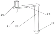
Fig. 2 is a structural schematic diagram of the roller dismounting device of the underground belt conveyor in the other direction.
Fig. 3 is a schematic structural view of the suspension clamp mechanism.
Fig. 4 is a schematic structural view of the lifting and rotating mechanism.
Fig. 5 is a schematic structural view of the mobile power mechanism.
In the figure: a suspension clamping mechanism 1; a lifting beam 1-1; rotating the clamping shaft 1-2; clamping the suspension arm 1-3; 1-4 of an arc-shaped clamping seat; 1-5 parts of a driven gear; output gears 1-6; clamping a motor 1-7; a lifting and rotating mechanism 2; rotating the upright post 2-1; rotating the annular rack 2-2; 2-3 of a bearing cross beam; 2-4 of a lifting cylinder; a mobile power mechanism 3; a mobile trolley board 3-1; 3-2 of self-locking universal wheels; 3-3 of a rotating motor; 3-4 of a push-pull handle; 3-5 of a motor mounting plate; the gears 3-6 are rotatably driven.
Detailed Description
The first embodiment is as follows:
the following description of the embodiment is provided with reference to fig. 1, 2, 3, 4 and 5, and the present invention relates to the technical field of roller dismounting, and more specifically to a roller dismounting device for an underground belt conveyor, which comprises a suspension clamping mechanism 1, a lifting rotating mechanism 2 and a mobile power mechanism 3, wherein the lifting rotating mechanism 2 is rotatably connected to the mobile power mechanism 3, the suspension clamping mechanism 1 is fixedly connected to the lifting rotating mechanism 2, the suspension clamping mechanism 1 comprises a lifting beam 1-1, a rotating clamping shaft 1-2, a clamping boom 1-3, an arc-shaped clamping seat 1-4, a driven gear 1-5, an output gear 1-6 and a clamping motor 1-7, the clamping motor 1-7 is detachably connected to the lifting beam 1-1 through a bolt, the output gear 1-6 is fixedly connected to an output shaft of the clamping motor 1-7, the two rotary clamping shafts 1-2 are rotatably connected to the lifting cross beam 1-1, the right end of one rotary clamping shaft 1-2 is fixedly connected to the output gear 1-6, the driven gear 1-5 is fixedly connected to the right end of the other rotary clamping shaft 1-2, the driven gear 1-5 is in meshing transmission with the output gear 1-6, the two rotary clamping shafts 1-2 are respectively and fixedly connected with two clamping suspension arms 1-3, the four arc-shaped clamping seats 1-4 are respectively and fixedly connected to the bottom ends of the four clamping suspension arms 1-3, and the lifting cross beam 1-1 is fixedly connected to the lifting rotating mechanism 2; the clamping motor 1-7 drives the output gear 1-6 to rotate, the output gear 1-6 drives the driven gear 1-5 to rotate, the output gear 1-6 and the driven gear 1-5 respectively drive the two rotating clamping shafts 1-2 to rotate, the two rotating clamping shafts 1-2 respectively drive the four clamping suspension arms 1-3 and the four arc-shaped clamping seats 1-4 to open and close, and the carrier roller is fastened, fixed and loosened.
The second embodiment is as follows:
the embodiment is described below with reference to fig. 1, 2, 3, 4, and 5, and the embodiment further describes the embodiment, where the lifting and rotating mechanism 2 includes a rotating column 2-1, a rotating annular rack 2-2, a bearing beam 2-3, and a lifting cylinder 2-4, the lifting cylinder 2-4 is detachably connected to the left end of the bearing beam 2-3 through a bolt, the right end of the bearing beam 2-3 is fixedly connected to the top end of the rotating column 2-1, the bottom end of the rotating column 2-1 is rotatably connected to a moving power mechanism 3, the rotating annular rack 2-2 is fixedly connected to the rotating column 2-1, and the lifting beam 1-1 is fixedly connected to an output shaft of the lifting cylinder 2-4; the lifting cylinder 2-4 drives the lifting cross beam 1-1 to lift so as to realize that the carrier roller is taken out from the disassembly position, and the rotary annular rack 2-2 drives the rotary upright post 2-1 to rotate on the moving power mechanism 3 so as to realize that the carrier roller is rotated and moved away from the disassembly position.
The third concrete implementation mode:
the second embodiment is further described with reference to fig. 1, 2, 3, 4 and 5. the second embodiment is further described with reference to the first embodiment, the moving power mechanism 3 includes a moving cart plate 3-1, a self-locking universal wheel 3-2, a rotating motor 3-3, a push-pull handle 3-4, a motor mounting plate 3-5 and a rotating drive gear 3-6, the rotating drive gear 3-6 is fixedly connected to an output shaft of the rotating motor 3-3, the rotating motor 3-3 is detachably connected to the motor mounting plate 3-5 through a bolt, the motor mounting plate 3-5 is fixedly connected to the moving cart plate 3-1, the self-locking universal wheel 3-2 is fixedly connected to four corners of the bottom end of the moving cart plate 3-1, the push-pull handle 3-4 is fixedly connected to the right end of the moving cart plate 3-1, the bottom end of the rotary upright post 2-1 is rotatably connected to the movable trolley plate 3-1, and the rotary driving gear 3-6 and the rotary annular rack 2-2 are in transmission through a chain; an operator can drive four self-locking universal wheels 3-2 to walk by pushing and pulling handles 3-4 to move the carrier roller, the rotating motor 3-3 drives the rotating driving gear 3-6 to rotate, and the rotating driving gear 3-6 drives the rotating annular rack 2-2 to rotate, so that the rotating upright post 2-1 rotates on the moving trolley board 3-1.
The fourth concrete implementation mode:
the third embodiment is further described below with reference to fig. 1, 2, 3, 4, and 5, wherein the clamping motors 1 to 7 and the rotating motors 3 to 3 are both provided with band-type brakes; the four arc-shaped clamping seats 1-4 are prevented from accidentally loosening the carrier roller and the rotating upright post 2-1 from accidentally rotating.
The fifth concrete implementation mode:
the present embodiment is described below with reference to fig. 1, 2, 3, 4, and 5, and the present embodiment further describes a third embodiment, in which the two rotating clamp shafts 1-2 have opposite rotating directions; the idler is clamped and loosened.
The sixth specific implementation mode:
the third embodiment is further described below with reference to fig. 1, 2, 3, 4, and 5, wherein rubber pads are disposed on the surfaces of the four arc-shaped clamping seats 1-4; can protect the bearing roller surface, prevent by fish tail or damage.
The utility model relates to a belt conveyor bearing roller dismounting device's in pit theory of operation: an operator uses a push-pull handle 3-4 to drive four self-locking universal wheels 3-2 to walk, a moving power mechanism 3 is moved to a disassembly position, a rotating motor 3-3 is started, the rotating motor 3-3 drives a rotating driving gear 3-6 to rotate, the rotating driving gear 3-6 drives a rotating annular rack 2-2 to rotate, so that a rotating upright post 2-1 rotates on a moving trolley board 3-1, the rotating upright post 2-1 drives a lifting cylinder 2-4 and a lifting beam 1-1 to rotate right above a carrier roller, a lifting cylinder 2-4 is started, the lifting cylinder 2-4 drives the lifting beam 1-1 to descend, the carrier roller is positioned between four arc-shaped clamping seats 1-4 and four clamping suspension arms 1-3, and the clamping motor 1-7 is started, the clamping motor 1-7 drives the output gear 1-6 to rotate, the output gear 1-6 drives the driven gear 1-5 to rotate, the output gear 1-6 and the driven gear 1-5 respectively drive the two rotating clamping shafts 1-2 to rotate, the two rotating clamping shafts 1-2 respectively drive the four clamping suspension arms 1-3 and the four arc-shaped clamping seats 1-4 to close, the carrier roller is clamped and fixed, after an operator finishes disassembling the carrier roller, the lifting air cylinder 2-4 drives the lifting cross beam 1-1 to ascend, the carrier roller is lifted, the operator drives the four self-locking universal wheels 3-2 to walk by using the push-pull handle 3-4 again, the carrier roller is moved to a storage position, the lifting air cylinder 2-4 drives the lifting cross beam 1-1 to descend, and finally the clamping motor 1-7 drives the output gear 1-6 to rotate, the output gear 1-6 drives the driven gear 1-5 to rotate, the output gear 1-6 and the driven gear 1-5 respectively drive the two rotary clamping shafts 1-2 to rotate, the two rotary clamping shafts 1-2 respectively drive the four clamping suspension arms 1-3 and the four arc-shaped clamping seats 1-4 to open, and the carrier roller is released and placed at a storage position.
Of course, the above description is not intended to limit the present invention, and the present invention is not limited to the above examples, and the changes, modifications, additions or replacements made by those skilled in the art within the scope of the present invention also belong to the protection scope of the present invention.
Claims (6)
1. The utility model provides a belt conveyor bearing roller dismounting device in pit, suspends clamping mechanism (1), lifting and drop rotating mechanism (2) and mobile power unit (3) in midair, lifting and drop rotating mechanism (2) rotate to be connected on mobile power unit (3), suspend clamping mechanism (1) fixed connection in midair on lifting and drop rotating mechanism (2), its characterized in that: the suspension clamping mechanism (1) comprises a lifting beam (1-1), rotary clamping shafts (1-2), a clamping suspension arm (1-3), an arc-shaped clamping seat (1-4), driven gears (1-5), output gears (1-6) and clamping motors (1-7), wherein the clamping motors (1-7) are detachably connected to the lifting beam (1-1) through bolts, the output gears (1-6) are fixedly connected to output shafts of the clamping motors (1-7), the two rotary clamping shafts (1-2) are rotatably connected to the lifting beam (1-1), the right end of one rotary clamping shaft (1-2) is fixedly connected to the output gears (1-6), the driven gear (1-5) is fixedly connected to the right end of the other rotary clamping shaft (1-2), the driven gear (1-5) and the output gear (1-6) are in meshing transmission, two clamping suspension arms (1-3) are respectively and fixedly connected to the two rotating clamping shafts (1-2), four arc-shaped clamping seats (1-4) are respectively and fixedly connected to the bottom ends of the four clamping suspension arms (1-3), and the lifting beam (1-1) is fixedly connected to the lifting rotating mechanism (2).
2. A downhole belt conveyor idler dismounting device according to claim 1, wherein: the lifting and rotating mechanism (2) comprises a rotating upright post (2-1), a rotating annular rack (2-2), a bearing cross beam (2-3) and a lifting cylinder (2-4), the lifting cylinder (2-4) is detachably connected to the left end of the bearing cross beam (2-3) through a bolt, the right end of the bearing cross beam (2-3) is fixedly connected to the top end of the rotating upright post (2-1), the bottom end of the rotating upright post (2-1) is rotatably connected to a movable power mechanism (3), the rotating annular rack (2-2) is fixedly connected to the rotating upright post (2-1), and the lifting cross beam (1-1) is fixedly connected to an output shaft of the lifting cylinder (2-4).
3. A downhole belt conveyor idler dismounting device according to claim 2, wherein: the moving power mechanism (3) comprises a moving trolley plate (3-1), self-locking universal wheels (3-2), a rotating motor (3-3), a push-pull handle (3-4), a motor mounting plate (3-5) and a rotating driving gear (3-6), the rotating driving gear (3-6) is fixedly connected on an output shaft of the rotating motor (3-3), the rotating motor (3-3) is detachably connected on the motor mounting plate (3-5) through bolts, the motor mounting plate (3-5) is fixedly connected on the moving trolley plate (3-1), the self-locking universal wheels (3-2) are fixedly connected at four corners of the bottom end of the moving trolley plate (3-1), the push-pull handle (3-4) is fixedly connected at the right end of the moving trolley plate (3-1), the bottom end of the rotary upright post (2-1) is rotatably connected to the movable trolley board (3-1), and the rotary driving gear (3-6) and the rotary annular rack (2-2) are in transmission through a chain.
4. A downhole belt conveyor idler dismounting device according to claim 3, wherein: and the clamping motors (1-7) and the rotating motors (3-3) are respectively provided with a band-type brake.
5. A downhole belt conveyor idler dismounting device according to claim 3, wherein: the two rotating clamping shafts (1-2) have opposite rotating directions.
6. A downhole belt conveyor idler dismounting device according to claim 3, wherein: rubber pads are arranged on the surfaces of the four arc-shaped clamping seats (1-4).
Priority Applications (1)
| Application Number | Priority Date | Filing Date | Title |
|---|---|---|---|
| CN202020205757.5U CN211681833U (en) | 2020-02-25 | 2020-02-25 | Roller dismounting device of underground belt conveyor |
Applications Claiming Priority (1)
| Application Number | Priority Date | Filing Date | Title |
|---|---|---|---|
| CN202020205757.5U CN211681833U (en) | 2020-02-25 | 2020-02-25 | Roller dismounting device of underground belt conveyor |
Publications (1)
| Publication Number | Publication Date |
|---|---|
| CN211681833U true CN211681833U (en) | 2020-10-16 |
Family
ID=72777305
Family Applications (1)
| Application Number | Title | Priority Date | Filing Date |
|---|---|---|---|
| CN202020205757.5U Active CN211681833U (en) | 2020-02-25 | 2020-02-25 | Roller dismounting device of underground belt conveyor |
Country Status (1)
| Country | Link |
|---|---|
| CN (1) | CN211681833U (en) |
Cited By (1)
| Publication number | Priority date | Publication date | Assignee | Title |
|---|---|---|---|---|
| CN112975830A (en) * | 2021-04-16 | 2021-06-18 | 辽宁工程技术大学 | Carrier roller replacing vehicle of belt conveyor in working state |
-
2020
- 2020-02-25 CN CN202020205757.5U patent/CN211681833U/en active Active
Cited By (2)
| Publication number | Priority date | Publication date | Assignee | Title |
|---|---|---|---|---|
| CN112975830A (en) * | 2021-04-16 | 2021-06-18 | 辽宁工程技术大学 | Carrier roller replacing vehicle of belt conveyor in working state |
| CN112975830B (en) * | 2021-04-16 | 2022-06-14 | 辽宁工程技术大学 | Carrier roller replacing vehicle of belt conveyor in working state |
Similar Documents
| Publication | Publication Date | Title |
|---|---|---|
| CN201455117U (en) | Adjustable electric quick model changing vehicle | |
| CN103752616A (en) | Roller bearing block detacher | |
| CN211681833U (en) | Roller dismounting device of underground belt conveyor | |
| CN104495636B (en) | A kind of balance crane assembling device | |
| CN219860281U (en) | Power assisting device for replacing central cover plate of bridge | |
| CN218319349U (en) | A transport frame for automobile engine cylinder block transportation | |
| CN209873593U (en) | Bridge erecting machine | |
| CN208603602U (en) | A kind of hydraulic engineering trash rack maintenance hoisting device | |
| CN208327184U (en) | A kind of construction of hydro project trash rack lifting mounting device | |
| CN108217500A (en) | A kind of folded form industry hanging apparatus easy to remove | |
| CN210317130U (en) | Movable telescopic ladder | |
| CN211219516U (en) | Intelligent press-fitting equipment for double mechanical arm bearings | |
| CN201525726U (en) | Electric lifting carrying device | |
| CN210374678U (en) | Carbon crucible outer wall slag remover | |
| CN204434117U (en) | A kind of balance crane assembling device | |
| CN208120645U (en) | A kind of folded form industry hanging apparatus easy to remove | |
| CN220354848U (en) | Auxiliary travelling mechanism for large workbench | |
| CN2509040Y (en) | Side-frame moving bolster overturning apparatus | |
| CN205702917U (en) | A kind of grabbing workpiece automation equipment | |
| CN219585763U (en) | Steel structure installation device | |
| CN215746377U (en) | Large-scale sand box mould assembling turnover machine | |
| CN218403414U (en) | Adjustable eccentric lifting appliance for motor installation | |
| CN211588024U (en) | I-shaped wheel dismounting device of removable steel wire production usefulness | |
| CN218708900U (en) | Roller changing trolley for cotton seed delinting machine saw roller | |
| CN212151397U (en) | Hoisting equipment for building engineering |
Legal Events
| Date | Code | Title | Description |
|---|---|---|---|
| GR01 | Patent grant | ||
| GR01 | Patent grant |