Processing machinery base reinforcing apparatus
Technical Field
The utility model relates to the technical field of machining, especially, relate to a processing machinery base reinforcing apparatus.
Background
Machining refers to a process of changing the external dimensions or properties of a workpiece by a mechanical device, wherein the machine for machining the workpiece may vibrate or even displace, which may affect the mechanical life and the machining operation, so that the base needs to be reinforced to ensure the operation stability.
The existing reinforcing device for the base of the processing machine only has the function of reinforcing the base of the processing machine, vibration generated in the processing process cannot be effectively eliminated, and the problems of reduced processing quality of workpieces, ground abrasion, reduced mechanical service life and the like caused by vibration cannot be solved.
SUMMERY OF THE UTILITY MODEL
The purpose of the utility model is to solve the shortcoming that exists among the prior art, if: the vibration generated by mechanical processing can not be effectively eliminated, and the reinforcing device for the base of the processing machine is provided.
In order to achieve the above purpose, the utility model adopts the following technical scheme:
the utility model provides a processing machinery base reinforcing apparatus, includes the bottom plate, the bottom plate upper surface is equipped with two backup pads that are parallel to each other, two the upper end inside wall fixedly connected with mounting panel of backup pad, the bottom plate upper surface still is equipped with two fixed blocks, two fixed blocks are located the outside of two backup pads respectively, two the backup pad lateral wall has all been seted up and has been accomodate the groove, two it all rotates to be connected with the reinforcement arm to accomodate the inslot, and two reinforcement arms keep away from the inclined plane fixed connection who accomodates the one end in groove and fixed block, it includes supporting shoe and a supporting cylinder to consolidate the arm, and the supporting shoe slides and sets up in a supporting cylinder, the bottom of a supporting cylinder is equipped with.
Preferably, damping device includes first connecting axle and two second connecting axles that two symmetries set up, two first connecting axle is horizontal symmetry setting, and two second connecting axles are vertical symmetry setting, all rotate between first connecting axle and the second connecting axle and be connected with the stress pole, and four stress poles are the rhombus setting, two be connected with the spring between the first connecting axle, one of them the second connecting axle rotates with the diapire of a support section of thick bamboo to be connected, still sliding connection has the connecting rod in the support section of thick bamboo, another the second connecting axle rotates with the lower extreme of connecting rod to be connected, the one end and the supporting shoe fixed connection of second connecting axle are kept away from to the connecting rod.
Preferably, rubber cushions are arranged at the bottoms of the two supporting plates.
Preferably, two all be equipped with the inclined plane on the fixed block, and two fixed blocks all pass through fastening bolt to be fixed on the bottom plate.
Preferably, lubricating grease is arranged between the supporting block and the inner wall of the supporting cylinder.
Compared with the prior art, the beneficial effects of the utility model are that:
through the reinforcement arm that sets up in fixed plate both sides, support power is provided for machining equipment base, avoid the base to empty about because of processing machinery operation, and simultaneously, the reinforcement arm comprises supporting shoe and damping device, damping device can effectually be eliminated the vibrations that processing machinery operated and produced, thereby avoid causing the work piece quality to descend because of vibrations, ground wearing and tearing, mechanical life reduces the scheduling problem, through the groove of accomodating that sets up in the backup pad, can not operate at processing machinery, accomodate the reinforcement arm when not needing to consolidate the shock attenuation, and the space is saved.
Drawings
Fig. 1 is a schematic structural view of a processing machine base reinforcing device provided by the present invention;
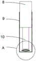
FIG. 2 is a schematic view of a reinforcement arm structure of a reinforcement device for a base of a processing machine of the present invention;
fig. 3 is a schematic structural diagram of a in fig. 2.
In the figure: the device comprises a base plate 1, support plates 2, a holding groove 3, a reinforcing arm 4, a fixing block 5, a fastening bolt 6, a mounting plate 7, a support block 8, a support cylinder 9, a connecting rod 10, a stress rod 11, a first connecting shaft 12, a spring 13 and a second connecting shaft 14.
Detailed Description
The technical solutions in the embodiments of the present invention will be described clearly and completely with reference to the accompanying drawings in the embodiments of the present invention, and it is obvious that the described embodiments are only some embodiments of the present invention, not all embodiments.
In the description of the present invention, it is to be understood that the terms "upper", "lower", "front", "rear", "left", "right", "top", "bottom", "inner", "outer", and the like indicate orientations or positional relationships based on the orientations or positional relationships shown in the drawings, and are only for convenience of description and simplicity of description, and do not indicate or imply that the device or element being referred to must have a particular orientation, be constructed and operated in a particular orientation, and therefore, should not be construed as limiting the present invention.
Referring to fig. 1-3, a processing machinery base reinforcing apparatus comprises a base plate 1, two parallel supporting plates 2 are arranged on the upper surface of the base plate 1, rubber cushion pads are arranged at the bottoms of the two supporting plates 2, vibration in the vertical direction can be effectively reduced, a mounting plate 7 is fixedly connected to the inner side walls of the upper ends of the two supporting plates 2, two fixing blocks 5 are further arranged on the upper surface of the base plate 1, the two fixing blocks 5 are respectively positioned at the outer sides of the two supporting plates 2, accommodating grooves 3 are respectively formed in the outer side walls of the two supporting plates 2, reinforcing arms 4 are rotatably connected in the two accommodating grooves 3, the reinforcing arms 4 play a reinforcing effect, one ends of the two reinforcing arms 4 far away from the accommodating grooves 3 are fixedly connected with the fixing blocks 5, inclined surfaces are arranged on the fixing blocks 5, the two fixing blocks 5 are fixed on the base plate 1 through fastening bolts, when a processing machine is not started or other machines do not need to be reinforced and damped, the reinforcing arm 4 is accommodated in the accommodating groove 3, the space is saved, the reinforcing arm 4 comprises a supporting block 8 and a supporting cylinder 9, the supporting block 8 is arranged in the supporting cylinder 9 in a sliding mode, lubricating grease is arranged between the supporting block 8 and the inner wall of the supporting cylinder 9, the problem that the damping effect cannot be achieved due to overlarge friction force is avoided, and a damping device connected with the supporting block 8 is arranged at the bottom of the supporting cylinder 9;
the damping device comprises two first connecting shafts 12 and two second connecting shafts 14 which are symmetrically arranged, the two first connecting shafts 12 are transversely symmetrically arranged, the two second connecting shafts 14 are vertically symmetrically arranged, stress rods 11 are rotatably connected between the first connecting shafts 12 and the second connecting shafts 14, the four stress rods 11 are arranged in a diamond shape, springs 13 are connected between the two first connecting shafts 12, one second connecting shaft 14 is rotatably connected with the bottom wall of a supporting cylinder 9, a connecting rod 10 is also slidably connected in the supporting cylinder 9, the other second connecting shaft 14 is rotatably connected with the lower end of the connecting rod 10, one end, far away from the second connecting shaft 14, of the connecting rod 10 is fixedly connected with a supporting block 8, after a processing machine is started, vibration is transmitted to the supporting plate 2 and a reinforcing arm 4 through a mounting plate 7, and a rubber cushion pad arranged at the bottom of the supporting plate 2 can effectively eliminate part of vibration, after the vibration is transmitted to the reinforcing arm 4, the supporting block 8 drives the connecting rod 10 to slide in the supporting cylinder 9, the connecting rod 10 applies a downward acting force to the second connecting shafts 14, the distance between the two second connecting shafts 14 is reduced, the distance between the two first connecting shafts 12 is increased, the spring 13 is subjected to a stretching force, and therefore the vibration received by the reinforcing arm 4 is effectively eliminated.
The utility model discloses in, processing machinery installs the upper surface at mounting panel 7, two backup pad 2 play the effect of supporting machinery, when processing machinery operation produced vibrations, vibrations transmit its bottom through backup pad 2 part, one of them part vibrations are installed and are absorbed at the rubber buffer pad of its bottom, in addition, vibrations can also transmit to the supporting shoe 8 of consolidating arm 4 through backup pad 2 on, bracing piece 8 drives connecting rod 10 and extrudees second connecting axle 14, distance between two first connecting axles 12 increases, make spring 13 receive the tensile force and eliminate vibrations with this.
The above, only be the concrete implementation of the preferred embodiment of the present invention, but the protection scope of the present invention is not limited thereto, and any person skilled in the art is in the technical scope of the present invention, according to the technical solution of the present invention and the utility model, the concept of which is equivalent to replace or change, should be covered within the protection scope of the present invention.