CN210890633U - Damping device for pumped storage power station unit - Google Patents
Damping device for pumped storage power station unit Download PDFInfo
- Publication number
- CN210890633U CN210890633U CN201922125376.6U CN201922125376U CN210890633U CN 210890633 U CN210890633 U CN 210890633U CN 201922125376 U CN201922125376 U CN 201922125376U CN 210890633 U CN210890633 U CN 210890633U
- Authority
- CN
- China
- Prior art keywords
- plate
- spring
- base
- power station
- storage power
- Prior art date
- Legal status (The legal status is an assumption and is not a legal conclusion. Google has not performed a legal analysis and makes no representation as to the accuracy of the status listed.)
- Active
Links
- 238000013016 damping Methods 0.000 title claims abstract description 26
- 238000003466 welding Methods 0.000 claims abstract description 6
- 230000000694 effects Effects 0.000 abstract description 10
- 239000000872 buffer Substances 0.000 abstract description 6
- 235000017166 Bambusa arundinacea Nutrition 0.000 abstract description 5
- 235000017491 Bambusa tulda Nutrition 0.000 abstract description 5
- 241001330002 Bambuseae Species 0.000 abstract description 5
- 235000015334 Phyllostachys viridis Nutrition 0.000 abstract description 5
- 239000011425 bamboo Substances 0.000 abstract description 5
- 230000001360 synchronised effect Effects 0.000 abstract description 3
- 230000017525 heat dissipation Effects 0.000 description 5
- 238000005457 optimization Methods 0.000 description 4
- 230000009286 beneficial effect Effects 0.000 description 3
- 230000002035 prolonged effect Effects 0.000 description 2
- 230000035939 shock Effects 0.000 description 2
- 238000010521 absorption reaction Methods 0.000 description 1
- 230000004075 alteration Effects 0.000 description 1
- 230000003139 buffering effect Effects 0.000 description 1
- 238000009434 installation Methods 0.000 description 1
- 238000000034 method Methods 0.000 description 1
- 238000012986 modification Methods 0.000 description 1
- 230000004048 modification Effects 0.000 description 1
- 238000006467 substitution reaction Methods 0.000 description 1
Images


Classifications
-
- Y—GENERAL TAGGING OF NEW TECHNOLOGICAL DEVELOPMENTS; GENERAL TAGGING OF CROSS-SECTIONAL TECHNOLOGIES SPANNING OVER SEVERAL SECTIONS OF THE IPC; TECHNICAL SUBJECTS COVERED BY FORMER USPC CROSS-REFERENCE ART COLLECTIONS [XRACs] AND DIGESTS
- Y02—TECHNOLOGIES OR APPLICATIONS FOR MITIGATION OR ADAPTATION AGAINST CLIMATE CHANGE
- Y02E—REDUCTION OF GREENHOUSE GAS [GHG] EMISSIONS, RELATED TO ENERGY GENERATION, TRANSMISSION OR DISTRIBUTION
- Y02E10/00—Energy generation through renewable energy sources
- Y02E10/20—Hydro energy
Abstract
The utility model relates to a pumped storage power station auxiliary assembly technical field, specific pumped storage power station unit damping device that says so, the on-line screen storage device comprises a base, base upper end middle part fixedly connected with guide cylinder, the guide cylinder outside has cup jointed a removal section of thick bamboo, the welding of removal section of thick bamboo up end has the connecting plate, fixed mounting has first spring between connecting plate and the base and in being located the guide cylinder. When the first spring and the second spring buffer unit vibrate, the fixed plate brings pressure to the connecting plate, the moving cylinder slides downwards outside the guide cylinder, the telescopic rod contracts, simple harmonic vibration of the third spring can be inhibited, damping force is generated, the vibration frequency of the unit is effectively reduced, and the damping effect is further achieved; the third spring also buffers pressure transmitted from the upper part of the fixing plate, the rubber threaded cylinder can inhibit simple harmonic vibration of the third spring, damping force is generated, the vibration frequency of the unit is effectively reduced, and then the synchronous damping effect is achieved.
Description
Technical Field
The utility model relates to a pumped storage power station auxiliary assembly technical field specifically is a pumped storage power station unit damping device.
Background
Electromechanical equipment required by the pumped storage unit has the characteristics of large size and weight. In most cases, large units are directly placed on the ground, the bottom of the large units is generally in direct contact with the ground, or a gasket is simply added below a foot rest, so that the purpose of preventing a machine tool from crushing and fracturing the ground is achieved. The unit can generate strong vibration and noise when working, the simple vibration damping pad has no substantial effect, can influence the surrounding environment, and is not beneficial to the long-time stable work of the unit. Therefore, the damping device for the pumped storage power station unit is provided.
SUMMERY OF THE UTILITY MODEL
An object of the utility model is to provide a pumped storage power station unit damping device to solve the problem that proposes in the above-mentioned background art.
In order to achieve the above object, the utility model provides a following technical scheme: a shock absorption device for a pumped storage power station unit comprises a base, wherein a guide cylinder is fixedly connected to the middle of the upper end of the base, a movable cylinder is sleeved on the outer side of the guide cylinder, a connecting plate is welded on the upper end face of the movable cylinder, a first spring is fixedly installed between the connecting plate and the base and positioned in the guide cylinder, fixed blocks are welded on the upper end of the base and positioned on the outer side of the guide cylinder in a circumferential equidistant mode, a telescopic rod is fixedly connected to the upper end of each fixed block, a second spring is sleeved on the outer side of the telescopic rod, a fixed plate is fixedly connected to the upper end of the connecting plate through bolts, rubber threaded cylinders are fixedly installed on the front side, the rear side and the left side and the right side of the base and the fixed plate, third springs are installed in the rubber threaded cylinders, a first side plate, and a mounting plate is welded between the first side plate and the second side plate.
As a further optimization of the technical scheme, a rubber pad is bonded at the bottom of the base.
As a further optimization of the technical scheme, guide rods are welded at four corners of the base, guide holes for the guide rods to penetrate through are formed in the fixed plate, limiting blocks are welded at the upper ends of the guide rods, and fourth springs are sleeved between the base and the fixed plate and outside the guide rods.
As a further optimization of the technical scheme, the mounting plate is provided with mounting holes.
As a further optimization of the technical scheme, the distance between the mounting plate and the fixing plate is 4-8 cm.
Compared with the prior art, the beneficial effects of the utility model are that: the utility model installs the unit on the upper end of the mounting plate, and a gap is left between the mounting plate and the fixed plate, which is beneficial to the heat dissipation of the unit; when the unit generates vibration during working, the vibration is transmitted to the fixing plate through the mounting plate, the first side plate and the second side plate, at the moment, the connecting plate senses pressure, so that the first spring and the second spring buffer the pressure of the fixing plate on the connecting plate, the movable cylinder slides downwards outside the guide cylinder, the telescopic rod contracts, simple harmonic vibration of the third spring can be inhibited, damping force is generated, the vibration frequency of the unit is effectively reduced, and the damping effect is further achieved; the third spring is used for buffering pressure transmitted from the upper side of the fixing plate, the rubber threaded cylinder can restrain simple harmonic vibration of the third spring, damping force is generated, the vibration frequency of the unit is effectively reduced, a synchronous damping effect is achieved, normal work of the unit is effectively guaranteed, and the service life of the unit is prolonged.
Drawings
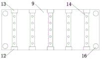
FIG. 1 is a schematic structural view of the present invention;
FIG. 2 is a schematic side view of the present invention;
fig. 3 is a schematic view of the top view structure of the present invention.
In the figure: the device comprises a base 1, a guide cylinder 2, a movable cylinder 3, a connecting plate 4, a first spring 5, a fixed block 6, a telescopic rod 7, a second spring 8, a fixed plate 9, a rubber threaded cylinder 10, a third spring 11, a first side plate 12, a second side plate 13, a mounting plate 14, a guide rod 15, a limiting block 16 and a fourth spring 17.
Detailed Description
The technical solutions in the embodiments of the present invention will be described clearly and completely with reference to the accompanying drawings in the embodiments of the present invention, and it is obvious that the described embodiments are only some embodiments of the present invention, not all embodiments. Based on the embodiments in the present invention, all other embodiments obtained by a person skilled in the art without creative work belong to the protection scope of the present invention.
Referring to fig. 1-3, the present invention provides a technical solution: the utility model provides a pumped storage power station unit damping device, includes base 1, during concrete setting, bonds the rubber pad in base 1 bottom, plays the shock attenuation and reduces the frictional effect of base 1.
The middle part of the upper end of the base 1 is fixedly connected with a guide cylinder 2, the outer side of the guide cylinder 2 is sleeved with a moving cylinder 3, the upper end face of the moving cylinder 3 is welded with a connecting plate 4, a first spring 5 is fixedly arranged between the connecting plate 4 and the base 1 and positioned in the guide cylinder 2, the upper end of the base 1 and positioned around the outer side of the guide cylinder 2 are welded with fixed blocks 6 at equal intervals in the circumferential direction, the upper end of each fixed block 6 is fixedly connected with a telescopic rod 7, the outer side of each telescopic rod 7 is sleeved with a second spring 8, the upper end of each connecting plate 4 is fixedly connected with a fixed plate 9 through a bolt, when the unit works, vibration is generated and transmitted to the fixed plate 9, at the moment, the connecting plate 4 senses pressure, the first spring 5 and the second spring 8 can buffer the pressure of the fixed plate 9 on the connecting plate 4, the moving cylinder 3 slides downwards on, effectively reduce the vibration frequency of unit, and then play the absorbing effect.
All fixed mounting have a rubber screw section of thick bamboo 10 around between base 1 and the fixed plate 9, install third spring 11 in the rubber screw section of thick bamboo 10, pressure that third spring 11 can cushion the fixed plate 9 top and transmit, and rubber screw section of thick bamboo 10 can restrain the simple harmonic vibration of third spring 11, produces the damping force, effectively reduces the vibration frequency of unit.
Specifically, all welding in the 1 four corners of base has guide bar 15, sets up the guiding hole that supplies guide bar 15 to pass on the fixed plate 9, and the welding has stopper 16 on guide bar 15, and the guide bar 15 outside has just been located and has cup jointed fourth spring 17 between base 1 and the fixed plate 9, and guide bar 15 plays the guide effect to fixed plate 9, avoids fixed plate 9 to take place the slope at the in-process of vibrations, influences the operation of top unit.
Specifically, when the heat dissipation device is used, the unit is arranged at the upper end of the mounting plate 14, and a gap is reserved between the mounting plate 14 and the fixing plate 9, so that the heat dissipation of the unit is facilitated; when the unit generates vibration during operation, the vibration is transmitted to the fixing plate 9 through the mounting plate 14, the first side plate 12 and the second side plate 13, at the moment, the connecting plate 4 senses pressure, so that the first spring 5 and the second spring 8 buffer the pressure which is brought to the connecting plate 4 by the fixing plate 9, the moving cylinder 3 slides downwards on the outer side of the guide cylinder 2, the telescopic rod 7 contracts, simple harmonic vibration of the third spring 11 can be inhibited, damping force is generated, the vibration frequency of the unit is effectively reduced, and a damping effect is further achieved; the third spring 11 also buffers the pressure transmitted from the upper part of the fixing plate 9, the rubber threaded cylinder 10 can inhibit the simple harmonic vibration of the third spring 11 to generate damping force, the vibration frequency of the unit is effectively reduced, the synchronous damping effect is further achieved, the normal work of the unit is effectively guaranteed, and the service life of the unit is prolonged.
Although embodiments of the present invention have been shown and described, it will be appreciated by those skilled in the art that changes, modifications, substitutions and alterations can be made in these embodiments without departing from the principles and spirit of the invention, the scope of which is defined in the appended claims and their equivalents.
Claims (5)
1. The utility model provides a pumped storage power station unit damping device, includes base (1), its characterized in that: the middle part of the upper end of the base (1) is fixedly connected with a guide cylinder (2), the outer side of the guide cylinder (2) is sleeved with a movable cylinder (3), the upper end surface of the movable cylinder (3) is welded with a connecting plate (4), a first spring (5) is fixedly arranged between the connecting plate (4) and the base (1) and positioned in the guide cylinder (2), the upper end of the base (1) is welded with fixed blocks (6) at the periphery of the outer side of the guide cylinder (2) in a circumferential equidistant manner, the upper end of each fixed block (6) is fixedly connected with a telescopic rod (7), the outer side of each telescopic rod (7) is sleeved with a second spring (8), the upper end of each connecting plate (4) is fixedly connected with a fixed plate (9) through bolts, rubber thread cylinders (10) are fixedly arranged at the front side, the rear side and the left side and the right side between the base (1, first curb plate (12) and second curb plate (13) have been welded to both sides equidistance respectively around fixed plate (9) upper end, first curb plate (12) and second curb plate (13) correspond the setting, the welding has mounting panel (14) between first curb plate (12) and second curb plate (13).
2. The pumped-storage power station unit damping device of claim 1, wherein: the bottom of the base (1) is bonded with a rubber pad.
3. The pumped-storage power station unit damping device of claim 1, wherein: base (1) four corners all welds guide bar (15), set up the guiding hole that supplies guide bar (15) to pass on fixed plate (9), the welding of guide bar (15) upper end has stopper (16), fourth spring (17) have been cup jointed in the guide bar (15) outside and between being located base (1) and fixed plate (9).
4. The pumped-storage power station unit damping device of claim 1, wherein: the mounting plate (14) is provided with a mounting hole.
5. The pumped-storage power station unit damping device of claim 1, wherein: the distance between the mounting plate (14) and the fixing plate (9) is 4-8 cm.
Priority Applications (1)
| Application Number | Priority Date | Filing Date | Title |
|---|---|---|---|
| CN201922125376.6U CN210890633U (en) | 2019-12-02 | 2019-12-02 | Damping device for pumped storage power station unit |
Applications Claiming Priority (1)
| Application Number | Priority Date | Filing Date | Title |
|---|---|---|---|
| CN201922125376.6U CN210890633U (en) | 2019-12-02 | 2019-12-02 | Damping device for pumped storage power station unit |
Publications (1)
| Publication Number | Publication Date |
|---|---|
| CN210890633U true CN210890633U (en) | 2020-06-30 |
Family
ID=71340930
Family Applications (1)
| Application Number | Title | Priority Date | Filing Date |
|---|---|---|---|
| CN201922125376.6U Active CN210890633U (en) | 2019-12-02 | 2019-12-02 | Damping device for pumped storage power station unit |
Country Status (1)
| Country | Link |
|---|---|
| CN (1) | CN210890633U (en) |
Cited By (2)
| Publication number | Priority date | Publication date | Assignee | Title |
|---|---|---|---|---|
| CN113623357A (en) * | 2021-10-11 | 2021-11-09 | 南通爱豆豆信息科技有限公司 | Shock attenuation protection device for mechanical equipment |
| CN114562541A (en) * | 2022-04-18 | 2022-05-31 | 国网新源控股有限公司 | Damping device for pumped storage power station unit |
-
2019
- 2019-12-02 CN CN201922125376.6U patent/CN210890633U/en active Active
Cited By (4)
| Publication number | Priority date | Publication date | Assignee | Title |
|---|---|---|---|---|
| CN113623357A (en) * | 2021-10-11 | 2021-11-09 | 南通爱豆豆信息科技有限公司 | Shock attenuation protection device for mechanical equipment |
| CN113623357B (en) * | 2021-10-11 | 2021-12-17 | 南通爱豆豆信息科技有限公司 | Shock attenuation protection device for mechanical equipment |
| CN114562541A (en) * | 2022-04-18 | 2022-05-31 | 国网新源控股有限公司 | Damping device for pumped storage power station unit |
| CN114562541B (en) * | 2022-04-18 | 2024-01-16 | 国网新源控股有限公司 | Shock-absorbing device for pumped storage power station unit |
Similar Documents
| Publication | Publication Date | Title |
|---|---|---|
| CN210890633U (en) | Damping device for pumped storage power station unit | |
| CN211693364U (en) | Small-size building engineering machinery shock attenuation equipment | |
| CN105729232A (en) | Two-way damping buffer base of machine tool | |
| CN210327249U (en) | Active damping and silencing device for vibrating motor | |
| CN105729134A (en) | Damping buffer base of machine tool | |
| CN210600712U (en) | Combined base for diesel generator | |
| CN210350935U (en) | Synchronous motor with supporting vibration damping mount | |
| CN210004040U (en) | shock-absorbing device for shield machine | |
| CN210780368U (en) | Noise-reduction heat dissipation device for motor | |
| CN210342304U (en) | Assembled building shock-absorbing structure | |
| CN214959079U (en) | Anti-resonance motor | |
| CN213496856U (en) | Pipe cutting machine with damping device | |
| CN212899530U (en) | Electromechanical device damping device | |
| CN211875497U (en) | Oil pump shock attenuation strutting arrangement | |
| CN212323884U (en) | Motor with energy absorption and shock absorption functions | |
| CN211116468U (en) | Type of making an uproar vacuum pump falls in antidetonation | |
| CN203628192U (en) | Auxiliary support device used for fatigue life test of transmission | |
| CN202806750U (en) | Elastic support of mounting base of transmission box for internal combustion power car | |
| CN214255672U (en) | High-voltage cable branch box with shock-absorbing function | |
| CN218934852U (en) | Industrial boiler feed pump supporting component | |
| CN210914902U (en) | Elevator traction machine mounting structure | |
| CN212455339U (en) | Damping device of hammer crusher | |
| CN112240277A (en) | Type of making an uproar vacuum pump falls in antidetonation | |
| CN214236567U (en) | Metal sawing machine | |
| CN216741887U (en) | Air compressor machine damping device |
Legal Events
| Date | Code | Title | Description |
|---|---|---|---|
| GR01 | Patent grant | ||
| GR01 | Patent grant |